
Related Manuals for Festo VT32 Series


Summary of Contents for Festo VT32 Series
- Page 1 MPA valve terminal MPA pneumatics manual Valve terminal with MPA pneumatics Type VT32−.. Manual 534 241 en 0302NH [665 561]...
- Page 3 ....... . . 534 241 E (Festo AG & Co. KG, D 73726 Esslingen, Federal Republic of Germany, 2003) Internet: http://www.festo.com...
- Page 4 Contents and general instructions Festo P.BE−MPA−EN en 0302NH...
-
Page 5: Table Of Contents
Address assignment of the valves ........3−24 Festo P.BE−MPA−EN en 0302NH... - Page 6 ........5−27 Festo P.BE−MPA−EN en 0302NH...
- Page 7 ............C−3 Festo P.BE−MPA−EN en 0302NH...
- Page 8 Contents and general instructions Festo P.BE−MPA−EN en 0302NH...
-
Page 9: Designated Use
National and local safety regulations must also be observed. Target group This manual is directed exclusively at technicians trained in control and automation technology. Service Please consult your local Festo repair service if you have any technical problems. Festo P.BE−MPA−EN en 0302NH... -
Page 10: Notes On This Manual
The following table provides an overview. with MP connection: Information on the electric/electronic components: see leaflet with product Table. 0/1: Connection variants of the MPA valve terminal VIII Festo P.BE−MPA−EN en 0302NH... - Page 11 CPX−... Table. 0/2: Manuals on the MPA valve terminal with CPX terminal Festo P.BE−MPA−EN en 0302NH...
- Page 12 Fig. 0/1: Main components of the MPA valve terminal This manual contains the documentation for the valve plates with Ident. codes B, D, E, G, H, J, K, M, N and X (see chapterSystem overview, description of components"). Festo P.BE−MPA−EN en 0302NH...
-
Page 13: Important User Instructions
This means that failure to observe this instruction may result in damage to property. The following pictogram marks passages in the text which describe activities with electrostatically sensitive compo nents. Electrostatically sensitive components may be damaged if they are not handled correctly. Festo P.BE−MPA−EN en 0302NH... - Page 14 Accessories: Information on necessary or sensible accessories for the Festo product. Environment: Information on environment−friendly use of Festo products. Text markings The bullet indicates activities which may be carried out in · any order. 1. Figures denote activities which must be carried out in the numerical order specified.
- Page 15 MPA valve terminal variant with sub−D plug via which all valve solenoid coils multipin connection (MP are centrally connected. connection) Pneumatic interface The pneumatic interface is the interface between the modular electrical periphery of the CPX terminal and the MPA pneumatics. XIII Festo P.BE−MPA−EN en 0302NH...
- Page 16 Connecting the tubing Connecting the supply lines (tubing) to the MPA valve terminal Supply unit Unit for additional supply of compressed air to the valve plates, e.g. with several pressure zones Table. 0/3: Product−specific terms and abbreviations Festo P.BE−MPA−EN en 0302NH...
- Page 17 Summary of components Chapter 1 1−1 Festo P.BE−MPA−EN en 0302NH...
- Page 18 Description of components ....... . 1−7 1−2 Festo P.BE−MPA−EN en 0302NH...
-
Page 19: Summary Of Components
Information on the modules of the CPX terminal can be found in the CPX system manual. Information on the electronic modules of the MPA valve ter minal can be found in the CPX I/O modules manual. 1−3 Festo P.BE−MPA−EN en 0302NH... -
Page 20: The Mpa Valve Terminal
1. Summary of components The MPA valve terminal Festo assists you in solving your automation tasks at machine level with MPA valve terminals. The modular structure of the MPA valve terminal enables you to use this valve terminal optimally in your machine or system. -
Page 21: Overview Of Variants
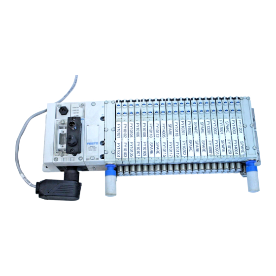
MPA valve terminal MPA valve terminal with This MPA valve terminal is available with 4 to max. 32 valve CPX terminal locations. Maximum 64 valve coils can be actuated. Fig. 1/1: MPA valve terminal with CPX terminal 1−5 Festo P.BE−MPA−EN en 0302NH... - Page 22 Fig. 1/2: MPA valve terminal with multipin connection Sizes of the MPA valve ter All MPA valve terminal variants are available with valves in minal sizes of 10 mm (MPA1). 1−6 Festo P.BE−MPA−EN en 0302NH...
-
Page 23: Description Of Components
Sheet seal (optional with pressure zone separation) Valve plates or blanking plates Further optional CPX modules Supply unit with exhaust plate or large surface−mounted silencer End plate Fig. 1/3: Components of the MPA valve terminal with CPX terminal 1−7 Festo P.BE−MPA−EN en 0302NH... - Page 24 Valve plates or blanking plates Sheet seal (optional with pressure zone separation, for forming maximum Supply unit with exhaust plate or large 2 pressure zones) surface−mounted silencer Fig. 1/4: Components of the MPA valve terminal with MP connection 1−8 Festo P.BE−MPA−EN en 0302NH...
- Page 25 2 solenoid coils, the maximum possible number of valve locations will be reduced. See also table 3/5 in chapter 3. Table 1/1: Maximum number of valve locations depending on the MPA valve terminal variants 1−9 Festo P.BE−MPA−EN en 0302NH...
- Page 26 Valve plate, two 3/2−way, single−solenoid, in basic position open Valve plate, 3/2−way, single−solenoid, in basic position closed external auxiliary pilot air Table 1/2: Ident. codes of the valve plates Further information on the valve plates can be found in Ap pendix B. 1−10 Festo P.BE−MPA−EN en 0302NH...
- Page 27 Pilot air exhaust connection (82/84) Compressed air connections (1) Work connections (2, 4) per valve plate Pilot air connection (12/14) Manual override cap Fig. 1/5: Pneumatic connecting and operating elements of the MPA valve terminal 1−11 Festo P.BE−MPA−EN en 0302NH...
- Page 28 Field bus connection (bus specific) LEDs yellow: Signal status display of the pilot solenoids red: Fault display Identification fields Power supply connection Earth/ground connection Fig. 1/6: Electrical connecting and display elements of the MPA valve terminal with CPX terminal 1−12 Festo P.BE−MPA−EN en 0302NH...
- Page 29 Inscription label holder with inscription field for ad dresses Earth/ground connection Sub−D connection LEDs yellow: Signal status display of the pilot solenoids Fig. 1/7: Electrical connecting and display elements of the MPA valve terminal with MP connection 1−13 Festo P.BE−MPA−EN en 0302NH...
- Page 30 1. Summary of components 1−14 Festo P.BE−MPA−EN en 0302NH...
-
Page 31: Fitting
Fitting Chapter 2 2−1 Festo P.BE−MPA−EN en 0302NH... -
Page 32: Fitting/Removing The Manual Override Cap (Optional)
......2−13 Fitting/removing the manual override cap (optional) ....2−15 2−2 Festo P.BE−MPA−EN en 0302NH... - Page 33 Information on fitting and dismantling the I/O modules can be found in the manual CPX I/O modules. Information on fitting modules and components ordered at a later stage can be found in the leaflet supplied with product. 2−3 Festo P.BE−MPA−EN en 0302NH...
-
Page 34: Fitting
Handle all modules and components of the MPA valve ter minal with great care. Please note especially the following: The specified torques must be observed. Electrostatically sensitive components Do not therefore touch any contact surfaces. 2−4 Festo P.BE−MPA−EN en 0302NH... -
Page 35: Fitting Variants
Table 2/1: Methods of fitting the MPA valve terminal Please note Fit the MPA valve terminal so that there is sufficient space for heat dissipation and ensure that the maximum limits for temperatures are observed (see Technical specifica tions"). 2−5 Festo P.BE−MPA−EN en 0302NH... -
Page 36: Hat Rail Fitting/Removal
MPA valve terminal with MP connection: CPA−BG−NRH. This kit consists of 2 M4x10 screws and 2 clamping el ements. for MPA valve terminals with CPX terminal: CPX−CPA−BG−NRH. This kit consists of 3 M4x10 screws and 3 clamping elements. 2−6 Festo P.BE−MPA−EN en 0302NH... - Page 37 35 mm, height 7.5 mm). Make sure there is suffi cient space for connecting the power cables and com pressed air tubing. 3. Fasten the hat rail to the fastening surface at intervals of approx. every 100 mm. 2−7 Festo P.BE−MPA−EN en 0302NH...
- Page 38 Ô Ô Fig. 2/1: Fitting the MPA valve terminal onto a hat rail 7. Fasten the MPA valve terminal, as with the CPX terminal, against tilting or sliding by tightening the locking screw with 1.3 Nm.. 2−8 Festo P.BE−MPA−EN en 0302NH...
- Page 39 2. Swing the MPA valve terminal forwards from the hat rail (see Fig. 2/3). 3. Lift the MPA valve terminal off the hat rail (see Fig. 2/3). 2−9 Festo P.BE−MPA−EN en 0302NH...
-
Page 40: Fitting Onto / Removing From A Wall
Fig. 2/3: Dismantling the MPA valve terminal 2.2.2 Fitting onto / removing from a wall The end plates, the MP sub−base or the pneumatic interface have holes for fitting the terminal onto a wall (see table 2/3). 2−10 Festo P.BE−MPA−EN en 0302NH... - Page 41 Make sure there is sufficient space for connecting the power cables and compressed air tubing. 2. Drill mounting holes in the fastening surface. 3. Fasten the MPA valve terminal with M4 or M6 screws of sufficient length to the fastening surface. 2−11 Festo P.BE−MPA−EN en 0302NH...
- Page 42 1. Prevent a hanging−mounted MPA valve terminal from fal ling down before you loosen it from the fastening surface. 2. Loosen the fastening screws (see table 2/3). 3. Remove the MPA valve terminal from the fastening surface. 2−12 Festo P.BE−MPA−EN en 0302NH...
-
Page 43: Fitting/Removing The Inscription Label Holder
Clip the inscription label holders into the grooves in the · sub−bases (see diagram): Recess for the in scription label holder in the sub− base Inscription label holder Fig. 2/4: Fitting the inscription label holder 2−13 Festo P.BE−MPA−EN en 0302NH... - Page 44 (blade width max. 3.5 mm) to press down the snap hook (see diagram). Holes for unlock ing the inscrip tion label holder Inscription label holder Fig. 2/5: Dismantling the inscription label holder 3. Pull the inscription label holder out of the recess in the sub−base. 2−14 Festo P.BE−MPA−EN en 0302NH...
- Page 45 (see chapter 4, table 4/5). 2. Clip the manual override caps into the grooves in the manual overrides (see diagram): Manual override Manual override Fig. 2/6: Fitting the manual override caps 2−15 Festo P.BE−MPA−EN en 0302NH...
- Page 46 2. Fitting Dismantling Proceed as follows: Use a suitable screwdriver to lift the manual override caps · out of the manual overrides (see diagram): Fig. 2/7: Dismantling the manual override caps 2−16 Festo P.BE−MPA−EN en 0302NH...
- Page 47 Installation Chapter 3 3−1 Festo P.BE−MPA−EN en 0302NH...
-
Page 48: Installation
........3−24 3−2 Festo P.BE−MPA−EN en 0302NH... -
Page 49: Installation
I/O modules etc.) can be found in the relevant manuals for the CPX module. Detailed instructions on addressing the pneumatic modules of the MPA valve terminal with CPX terminal can be found in the Manual for the CPX I/O modules." 3−3 Festo P.BE−MPA−EN en 0302NH... -
Page 50: Preparing The Compressed Air
If possible, operate your system with non−lubricated com pressed air. This will prevent pollution of the environment. Festo pneumatic valves and cylinders have been designed so that, if used as intended, they will not require additional lu brication and will still achieve a long service life. - Page 51 Incorrect additional oil and too much residual oil content in the compressed air will reduce the service life of the valve terminal. Use Festo special oil OFSW−32 or the other oils listed in the Festo catalogue (as per DIN 51524−HLP32, basic viscosity 32cST at 40 °C).
- Page 52 A further indication of excessive lubrication is the colouring or status of the exhaust silencer. A distinctly yellow colouring of the filter element or drops of oil on the silencer indicate that the lubricator setting is too high. 3−6 Festo P.BE−MPA−EN en 0302NH...
-
Page 53: General Notes On Connecting The Tubing
2. Pull the locking ring 1 over the tube connection or tighten the locking screw2. 3. For reasons of clarity, group the tubing together with: tube straps or multiple hose holders 3−7 Festo P.BE−MPA−EN en 0302NH... - Page 54 MPA valve terminal. 1. Loosen the locking screw or press the locking ring of the screw connector. 2. Pull out the tubing. 3. Replace non−required screw connectors with blanking plugs 3. Fig. 3/2: Disconnecting the tubing 3−8 Festo P.BE−MPA−EN en 0302NH...
-
Page 55: Connecting The Mpa Valve Terminal
(optional) on the supply unit next to the right−hand end plate on the MPA valve terminal with MP connection: on the MP sub−base if necessary, on the supply unit next to the right−hand end plate 3−9 Festo P.BE−MPA−EN en 0302NH... - Page 56 In this case, the auxiliary pilot air in the pneumatic interface or in the MP sub−base is branched from supply channel 1. 3−10 Festo P.BE−MPA−EN en 0302NH...
- Page 57 MPA valve terminal is operated with different pres sure zones (see Figs. 3/4 and 3/5). Set the external auxiliary pilot air to correspond to the · operating pressure with which these valves are operated (see diagrams). 3−11 Festo P.BE−MPA−EN en 0302NH...
- Page 58 Operating pres sure at connec tion 1 [bar] Fig. 3/4: Diagram: External auxiliary pilot air as a factor of the operating pressure on valve plates with Ident. code M, J, B, E, G and X 3−12 Festo P.BE−MPA−EN en 0302NH...
-
Page 59: Mpa Valve Terminal With Pressure Zone Separation
MP sub−base must be oper ated with a pressure between 3 ... 8 bar. The number of pressure zones with which your MPA valve terminal is fitted, is indicated by the marking on the seal (see diagram.). 3−13 Festo P.BE−MPA−EN en 0302NH... - Page 60 Table 3/3: Sub−base seals, identification of the seal variants The following diagrams show as an example the assignment of the supply and exhaust connections to the valve plates on an MPA valve terminal with blocked channels 1, 3 and 5. 3−14 Festo P.BE−MPA−EN en 0302NH...
- Page 61 (e.g. of neighbouring pressure zones) must not lie next to each other. By fitting an additional supply unit within a pressure zone you can supply additional supply air or extract exhaust air. 3−15 Festo P.BE−MPA−EN en 0302NH...
- Page 62 Identification of the pressure zone di viding seal (projecting flag) Pressure zone 1 Supply unit for pressure zone 2 Pressure zone 2 Fig. 3/5: Example of MPA valve terminal with CPX terminal and 3 pressure zones 3−16 Festo P.BE−MPA−EN en 0302NH...
- Page 63 Ö Ö Ö Ö MP sub−base Supply unit Pressure zone 1 Identification of the pressure zone di viding seal (projecting flag) Pressure zone 2 Fig. 3/6: Example: MPA valve terminal with MP connection and 2 pressure zones 3−17 Festo P.BE−MPA−EN en 0302NH...
-
Page 64: Vacuum/Low Pressure Operation
The valve terminal is fitted with the following valve plates: 5/2−way valve, single−solenoid (Ident. code M) 5/2−way valve, double−solenoid (Ident. code J) 5/3−way valves (Ident. codes B, E and G) 3−18 Festo P.BE−MPA−EN en 0302NH... -
Page 65: Connecting The Pneumatic Tubing
84 will be vented through the surface−mounted silencer. Connection 82/84 on the supply unit is then sealed with a blanking plug. Fit the screw connector or the silencers according to the table below. Then connect the pneumatic tubing. 3−19 Festo P.BE−MPA−EN en 0302NH... - Page 66 1) Depending on your order, the MPA valve terminal may already be fitted with QS screw connectors. 2) Only with MPA valve terminals with exhaust plate or supply unit Table 3/4: Assignment of connections 3−20 Festo P.BE−MPA−EN en 0302NH...
- Page 67 82/84 in order to prevent functional impairment due to back pressures. MPA valve ter minal 1 common 3/5 central 82/84 central 3/5 MPA valve ter minal 2 common 82/84 Fig. 3/8: Common lines with non−return valves 3−21 Festo P.BE−MPA−EN en 0302NH...
-
Page 68: Connecting The Electric Cables
By the use of PELV power units, protection against electric shock (protection against direct and indirect contact) is guar anteed with the Festo valve terminals in accordance with EN 60204−1 / IEC 204. Safety transformers with the adjacent symbol must be used for supplying PELV networks. The devi ce must be earthed to ensure that it functions correctly (e.g. - Page 69 Fig. 3/9: Earthing the MPA valve terminal Detailed instructions on the earthing measures to be under taken on the MPA valve terminals with CPX terminal can be found in chapter 3 in the CPX system manual. 3−23 Festo P.BE−MPA−EN en 0302NH...
-
Page 70: Address Assignmentof The Valves
Each valve location occupies 2 addresses, irrespective of the valve plate or blanking plate which is fitted. The following assignment applies: Solenoid coil 14 occupies the lower−value address, solenoid coil 12 occupies the higher−value address. 3−24 Festo P.BE−MPA−EN en 0302NH... - Page 71 Fig. 3/10: Example: Address assignment of a MPA valve terminal with CPX terminal and 8 valve locations (top view) Detailed instructions on addressing the pneumatic modules of the MPA valve terminal with CPX terminal can be found in the manual for the CPX I/O modules. 3−25 Festo P.BE−MPA−EN en 0302NH...
- Page 72 4 ... 19 −−− all valve locations Two solenoid coils per valve location can be controlled. One solenoid coil per valve location can be controlled. Table 3/5: Address assignment on the MPA valve terminal with MP connection 3−26 Festo P.BE−MPA−EN en 0302NH...
- Page 73 Addresses of coil 14 Valve plates on valve locations which occupy one address each. Fig. 3/11: Example: Address assignment of an MPA valve terminal with MP connection and 16 valve locations (top view) 3−27 Festo P.BE−MPA−EN en 0302NH...
- Page 74 3. Installation 3−28 Festo P.BE−MPA−EN en 0302NH...
- Page 75 Commissioning Chapter 4 4−1 Festo P.BE−MPA−EN en 0302NH...
- Page 76 ........4−17 4.5.2 Operating states of the pneumatic system ....4−18 4−2 Festo P.BE−MPA−EN en 0302NH...
- Page 77 Checking the valve functions Operating the manual override Checking the valve−actuator combination Eliminating faults The assignment of the LEDs Further information Commissioning the CPX terminal is described in the appropri ate manual for the CPX field bus node. 4−3 Festo P.BE−MPA−EN en 0302NH...
-
Page 78: Commissioning
This can cause damage to the machine or system and even injury to human beings. Operate the valve terminal with external auxiliary pilot · air (3 ... 8 bar). Branch the auxiliary pilot air in front of the safety start−up valve (see diagram). 4−4 Festo P.BE−MPA−EN en 0302NH... - Page 79 Safety start−up valve (slow build up of pressure of com plete supply) Fig. 4/1: Example of valve−cylinder combination with slow increase in pressure of the complete supply 4−5 Festo P.BE−MPA−EN en 0302NH...
-
Page 80: Manual Override
After actuation the manual over ride is reset by a spring. manual override, locking The manual override remains ac tuated until it is reset by hand. Table 4/2: Actuation methods of the manual override 4−6 Festo P.BE−MPA−EN en 0302NH... - Page 81 8 10 12 14 16 17 18 19 20 21 22 23 Manual override for valve solenoid Manual override for valve solenoid coils 12 coils 14 Fig. 4/2: Position of the manual overrides (top view) 4−7 Festo P.BE−MPA−EN en 0302NH...
-
Page 82: Checking The Valves And The Valve−Actuator Combination
Table 4/3: Commissioning variants Commissioning the pneumatic components by means of the manual override is described below. Commissioning of the CPX terminal is described in the ap propriate manual for the CPX field bus node. 4−8 Festo P.BE−MPA−EN en 0302NH... - Page 83 Make sure that nobody is in the danger zone. 1. Switch on the compressed air supply. 2. Check the functioning and operation of each individual valve−actuator combination by actuating the manual override as shown in the following diagrams. 4−9 Festo P.BE−MPA−EN en 0302NH...
- Page 84 3. With the locking function of the manual override, make sure, after testing the valves, that all manual override actuations are in their basic positions. 4. Switch off the compressed air supply after checking the valves. 4−10 Festo P.BE−MPA−EN en 0302NH...
- Page 85 A valve which has been switched by an electric signal (in switch position), cannot be reset to the basic position when the manual override is actuated. The electric signal is dominant in this case. Reset the electric signal before actuating the manual · override. 4−11 Festo P.BE−MPA−EN en 0302NH...
- Page 86 Then turn the plunger in an anti− moves back to the basic position · clockwise direction as far as poss (not with double−solenoid valve, ible. Ident. code J)) Then release the plunger. · Table 4/5: Operating the non−locking manual override 4−12 Festo P.BE−MPA−EN en 0302NH...
- Page 87 These movements can cause injury to human beings and damage to property. Before commissioning, bring the manual override actua · tions into the basic position again. 4−13 Festo P.BE−MPA−EN en 0302NH...
- Page 88 12 12 12 12 12 override for valve solenoid coil 14 14 14 14 14 14 14 14 14 14 14 14 14 Fig. 4/3: Assignment of LEDs and manual override to the valve solenoid coils 4−14 Festo P.BE−MPA−EN en 0302NH...
- Page 89 CPX I/O modules) Table 4/6: Meaning of the LED display (MPA valve terminal with CPX terminal) Further instructions on commissioning and diagnosing the MPA pneumatic modules can be found in the manual for the CPX I/O modules. 4−15 Festo P.BE−MPA−EN en 0302NH...
- Page 90 (18 V ... 30 V DC) compressed air supply not OK pilot exhaust blocked servicing required Table 4/7: Meaning of the LED display (MPA valve terminal with MP connection) 4−16 Festo P.BE−MPA−EN en 0302NH...
- Page 91 (if necessary set as a factor of the operat ing pressure, see chapter 3) servicing required · Table 4/8: Operating status of the pneumatic system 4−17 Festo P.BE−MPA−EN en 0302NH...
- Page 92 MPA valve terminal slow start−up after If there are control signals, the auxi EMERGENCY STOP liary pilot air must have a pressure of 3 ... 8 bar immediately after being switched on Table 4/9: Pneumatic operating states 4−18 Festo P.BE−MPA−EN en 0302NH...
- Page 93 Maintenance and conversion Chapter 5 5−1 Festo P.BE−MPA−EN en 0302NH...
- Page 94 ........5−27 5−2 Festo P.BE−MPA−EN en 0302NH...
-
Page 95: Maintenance And Conversion
Information on fitting /removing components and on the elec trical connections can be found in the CPX system manual. MPA valve terminal with multipin connection: Instructions on connecting the electric components can be found in the leaflet supplied with the product. 5−3 Festo P.BE−MPA−EN en 0302NH... -
Page 96: General Precautionary Measures
Screw connections must be fitted free of offset and · mechanical tension. Check the seals for damage (IP 65). · The contact surfaces must be dry and clean (sealing · effect, avoid leakage and contact faults). 5−4 Festo P.BE−MPA−EN en 0302NH... -
Page 97: Dismantling The Mpa Valve Terminal
Instructions on loosening the electrical connections can be found in · the CPX system manual. MP connection Loosen and remove the fastening screws of the sub−D multipin plug. · Table 5/1: Loosening the electrical connections 5−5 Festo P.BE−MPA−EN en 0302NH... - Page 98 3. Pull the pneumatic tubing away from the screw connector. Fig. 5/1: Removing the tubing Dismantling the MPA valve terminal The procedure for dismantling the MPA valve terminal is de scribed in chapter 2. 5−6 Festo P.BE−MPA−EN en 0302NH...
-
Page 99: Servicing The Mpa Valve Terminal
3. Check the seal between the basis component and the surface−mounted silencer for damage. Replace the seal if it is damaged. 4. Fasten the silencer only with the original screws. Tighten the screws in diagonally opposite sequence with 1.0 Nm. 5−7 Festo P.BE−MPA−EN en 0302NH... -
Page 100: Replacing Mpa Valve Terminal Components
(total number of valve locations) (see chapter 3, table 3/5). Dismantling Proceed as follows: Use a narrow screwdriver to loosen the fastening screws · and remove the components from the sub−bases (see diagram). 5−8 Festo P.BE−MPA−EN en 0302NH... - Page 101 They must be fitted onto the guide pin of the component, so that the cone fits easily into the appropriate recess in the electronic module when it is mounted (alignment see Fig. 5/3). 5−9 Festo P.BE−MPA−EN en 0302NH...
- Page 102 Sub−base Electronic module Fig. 5/3: Fitting valve plates or blanking plates 4. Place the component on the sub−base. 5. Screw the component at first only slightly and then tighten with 0.25 Nm (− 20%). 5−10 Festo P.BE−MPA−EN en 0302NH...
-
Page 103: Replacing The Electronic Modules
(see section Removing valve plates or blanking plates). Dismantling Proceed as follows: 1. Loosen the screws with which the electronic module is fastened to the sub−base. 2. Pull the electronic module upwards out of the body of the sub−base. 5−11 Festo P.BE−MPA−EN en 0302NH... - Page 104 Type VMPA1−FB−EMS−8: electronic module with 8 outputs without electrical isolation of the supply voltages. The electronic modules type VMPA1−FB−... support the control of two valve solenoid coils per valve location. 5−12 Festo P.BE−MPA−EN en 0302NH...
- Page 105 VMPA1−MP−EMS−4: Electronic module with 4 out puts. One valve solenoid coil can be controlled per valve location. type VMPA1−MP−EMS−8: Electronic module with 8 outputs. Two valve solenoid coils can be controlled per valve loca tion. 5−13 Festo P.BE−MPA−EN en 0302NH...
-
Page 106: Fitting/Removing The Large Surface−Mounted Silencer Or The Exhaust Plate
2. Place the MPA valve terminal on a flat working surface. Please note MPA valve terminal with MP connection: Before dismantling the sub−bases, you must remove all components (valve plates, blanking plates and electronic modules) from all sub−bases. 5−14 Festo P.BE−MPA−EN en 0302NH... - Page 107 Ö Ö Ö Ö Ö Ö Ö Ö Fig. 5/4: Position of the screw connectors of the sub−bases and the right−hand end plate 4. Pull the relevant sub−base away from the neighbouring sub−bases. 5−15 Festo P.BE−MPA−EN en 0302NH...
- Page 108 Place the flat seal onto the guide pin of the sub−base. Guide pins Sheet seal (op tional with pres sure zone separ ation) Fig. 5/5: Fitting the sub−base 2. Place the new sub−base onto the sheet seal. 5−16 Festo P.BE−MPA−EN en 0302NH...
- Page 109 4. Mount the MPA valve terminals onto the fastening surface (see chapter 2 Fitting onto a wall" or Fitting onto a hat rail"). 5. Then fit the pneumatic and electrical connections (see chapter 3 Installation, connecting the MPA valve ter minal"). 5−17 Festo P.BE−MPA−EN en 0302NH...
-
Page 110: Converting The Mpa Valve Terminal
Mixed operation of the MPA valve terminal with internal and external auxiliary pilot air is not intended. Irrespective of the available pressure zones, all valve solenoid coils of the MPA valve terminal are supplied with the same auxili ary pilot air. 5−18 Festo P.BE−MPA−EN en 0302NH... - Page 111 The auxiliary pilot air is branched internally from con nection 1. Pressure zone separation is permitted. Unused connections must be sealed. Table 5/2: Components for operating the pilot control with internal or external auxiliary pilot air 5−19 Festo P.BE−MPA−EN en 0302NH...
- Page 112 Ducted exhaust Pilot control with ex VMPA...−FB−EPL−EU VMPA...−MP−EPL−EU connection 12/14 open ternal auxiliary pilot Large surface−mounted si lencer Exhausting via large surface−mounted si lencer Table 5/3: Variants of the pneumatic interface or MP sub−base 5−20 Festo P.BE−MPA−EN en 0302NH...
-
Page 113: Converting The Mpa Valve Terminal To Different Pressure Zones
The pressure zones are implemented by means of special sheet seals which separate the following channels: only the supply channel (1) supply channel (1) and exhaust channels (3 and 5) only exhaust channels (3 and 5) 5−21 Festo P.BE−MPA−EN en 0302NH... - Page 114 Channels 1, 3 and 5 blocked Channels 1, 3 and 5 blocked Channel 1 blocked Channel 1 blocked Channels 3 and 5 blocked Channels 3 and 5 blocked Table 5/5: Sub−base seals, identification of the seal variants 5−22 Festo P.BE−MPA−EN en 0302NH...
- Page 115 2. Place the MPA valve terminal on a flat working surface. 3. Loosen the sub−base at the point where you wish to insert the sheet seal for the pressure zone separation (see sec tion Dismantling sub−bases"). 5−23 Festo P.BE−MPA−EN en 0302NH...
- Page 116 4. Then fit the pneumatic and electrical connections (see chapter 3 Installation, connecting the MPA valve ter minal"). The following diagram shows the layout of pressure zones using as an example an MPA valve terminal with CPX ter minal. 5−24 Festo P.BE−MPA−EN en 0302NH...
- Page 117 Supply unit with connection 1 for supplying compressed air to the 2nd. pres sure zone Pneumatic interface with connection 1 for supplying compressed air to the 1st. pressure zone Fig. 5/7: Example of MPA valve terminal with CPX terminal and 3 pressure zones 5−25 Festo P.BE−MPA−EN en 0302NH...
- Page 118 (see sec tion Dismantling sub−bases"). Fitting Proceed as follows: 1. Insert the sheet seal for the pressure zone separation. 2. Fit the sub−base (see section Fitting sub−bases"). 5−26 Festo P.BE−MPA−EN en 0302NH...
-
Page 119: Adding Valve Locations
You can easily adapt the MPA valve terminal with CPX terminal to the demands of your machine or system by adding valve locations. The smallest extension unit is a sub−base with 4 valve loca tions. For extension you will require: 5−27 Festo P.BE−MPA−EN en 0302NH... - Page 120 1. Loosen the MPA valve terminal from the fastening surface (see section Dismantling the MPA valve terminal"). 2. Dismantle the sub−base or the supply plate at the point where you wish to extend the valve terminal (see section Dismantling sub−bases"). 5−28 Festo P.BE−MPA−EN en 0302NH...
- Page 121 3 Installation, connecting the MPA valve ter minal"). Please note If a sub−base is inserted between existing sub−bases, the address assignment of all the valves to the right of the inserted sub−base will be modified. 5−29 Festo P.BE−MPA−EN en 0302NH...
- Page 122 5. Maintenance and conversion 5−30 Festo P.BE−MPA−EN en 0302NH...
- Page 123 Technical appendix Appendix A A−1 Festo P.BE−MPA−EN en 0302NH...
- Page 124 ..........A−10 A−2 Festo P.BE−MPA−EN en 0302NH...
- Page 125 − 5 ... + 50 medium − 5 ... + 50 Protection class as per EN 60 529 IP 65 (with cable from Festo accessories) Relative humidity 90 % at 40 Protection against corrosion KBK1 (as per FN940070) Mounting position...
- Page 126 0.35 mm path at 10−60 Hz ±30 g at 11 ms duration; −−−−− 5 g acceleration at 60−150 Hz 5 shocks in each direction Table A/3: Values for vibration and shock as per DIN/IEC68 A−4 Festo P.BE−MPA−EN en 0302NH...
- Page 127 Valve location Ident. code D, H, N, K at connection 1: 3 ... 10 bar All valve plates: at connection 12/14: see relevant diagrams Manual override locking or non−locking Table A/4: Medium and pressure range A−5 Festo P.BE−MPA−EN en 0302NH...
- Page 128 Work range for valves with exter nal auxiliary pilot Work pressure P1 [bar] −1 Fig. A/2: Diagram: Pilot pressure with external auxiliary pilot air for valve plates with Ident. code M, J, B, E, G and X A−6 Festo P.BE−MPA−EN en 0302NH...
- Page 129 2 x 2/2−way valves N, K, H all 2 x 3/2−way valves 1 x 3/2−way valve, closed, 5/2−way valve (single−solenoid) 5/2−way valve (double−solenoid) B, G, E 5/3−way valves Table A/5: Rated flows and valve switching times A−7 Festo P.BE−MPA−EN en 0302NH...
- Page 130 (after 20 ms switch−on time) 1) The MPA valve terminal is intended for industrial usage. 2) The maximum signal cable length for MPA valve terminals with MP connection is 10 m Table A/6: Technical specifications for the electric components A−8 Festo P.BE−MPA−EN en 0302NH...
- Page 131 MPA valve terminal with MP connection are enclosed with the product. Technical specifications for the electronic module of the MPA valve terminal with CPX terminal can be found in the manual for the CPX I/O modules. A−9 Festo P.BE−MPA−EN en 0302NH...
- Page 132 MPA valve terminal with MP connection Ready−to−use multipin cable for terminals with 4 valve locations VMPA−KMS1−8−... for terminals with 8 ... 24 valve locations VMPA−KMS1−24 Multipin socket Table A/7: Accessories for the MPA valve terminal A−10 Festo P.BE−MPA−EN en 0302NH...
- Page 133 Supplementary overview of components Appendix B B−1 Festo P.BE−MPA−EN en 0302NH...
- Page 134 ......... B−3 Separating the MPA valve terminal from the CPX terminal ....B−7 B−2 Festo P.BE−MPA−EN en 0302NH...
- Page 135 Table B/1: Valve plates with 2/2−way valves Valve plates with 3/2−way valves Ident. code: K 82/84 Function: Two single−solenoid 3/2−way valves, basic position closed 12/14 Ident. code: N 82/84 Function: Two single−solenoid 3/2−way valves, basic position open 12/14 B−3 Festo P.BE−MPA−EN en 0302NH...
- Page 136 Number of assigned outputs on an MPA valve terminal with MP connection: The number of outputs, which are assigned to 12/14 this valve, depends on the valve location (see table 3/3). Table B/2: Valve plates with 3/2−way valves B−4 Festo P.BE−MPA−EN en 0302NH...
- Page 137 The number of outputs, which are assigned to this valve, depends on the valve location (see 12/14 table 3/3). Ident. code: J 82/84 Function: One 5/2−way valve, double−solenoid 12/14 Table B/3: Valve plates with 5/2−way valves B−5 Festo P.BE−MPA−EN en 0302NH...
- Page 138 5/3−way valve, mid position pressurized 12/14 Ident. code: G 82/84 Function: 5/3−way valve in mid−position blocked 12/14 5 Ident. code: E 82/84 Function: 5/3−way valve, in mid position exhausted 12/14 Table B/4: Valve plates with 5/3−way valves B−6 Festo P.BE−MPA−EN en 0302NH...
- Page 139 (see chapter 5, Dismantling the MPA valve terminal"). 2. Loosen the fastening screws between the pneumatic inter face and the MPA sub−base in the sequence 1 2 3 (see Fig. B/2). 3. Then loosen the fastening screws. B−7 Festo P.BE−MPA−EN en 0302NH...
- Page 140 CPX terminal. 3. Insert the fastening screws in the appropriate holes. Tighten the screws in the sequence specified in Fig. B/2 at first slightly and then with 1.3 Nm. B−8 Festo P.BE−MPA−EN en 0302NH...
- Page 141 5. Carry out the electrical and pneumatic connections of the CPX terminal. Information on this can be found in the electrics section of the CPX system manual in the pneumatics section in chapter 3 of this manual. B−9 Festo P.BE−MPA−EN en 0302NH...
- Page 142 B. Supplementary overview of components B−10 Festo P.BE−MPA−EN en 0302NH...
- Page 143 Index Appendix C C−1 Festo P.BE−MPA−EN en 0302NH...
- Page 144 ............C−3 C−2 Festo P.BE−MPA−EN en 0302NH...
- Page 145 Display elements MPA valve terminal with CPX terminal ... . 1−12 MPA valve terminal with multipin connection ..1−13 C−3 Festo P.BE−MPA−EN en 0302NH...
- Page 146 ........5−18 C−4 Festo P.BE−MPA−EN en 0302NH...
- Page 147 ....... 3−21 Notes on the use of this manual ....VIII C−5 Festo P.BE−MPA−EN en 0302NH...
- Page 148 ......5−14 Replacing valve plates ......5−8 C−6 Festo P.BE−MPA−EN en 0302NH...
- Page 149 ........A−4 C−7 Festo P.BE−MPA−EN en 0302NH...
- Page 150 C. Index C−8 Festo P.BE−MPA−EN en 0302NH...
Need help?
Do you have a question about the VT32 Series and is the answer not in the manual?
Questions and answers