Table of Contents
Advertisement
Advertisement
Table of Contents

Subscribe to Our Youtube Channel
Related Manuals for Stenner Pumps ECON T Series


Summary of Contents for Stenner Pumps ECON T Series
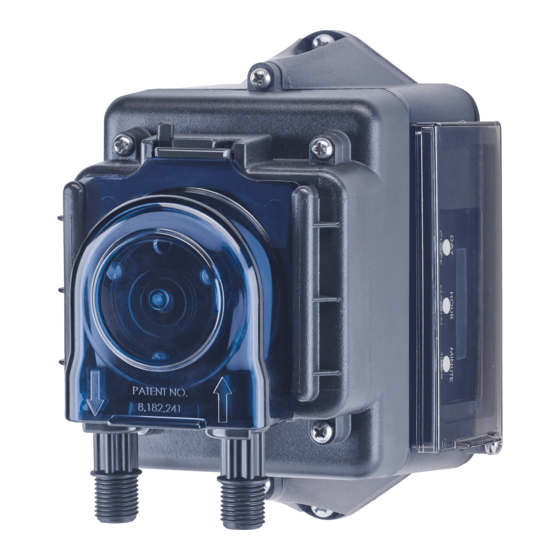
- Page 1 PERISTALTIC METERING PUMPS SINCE 1957 ECON T PUMP SERIES PERISTALTIC METERING PUMP INSTALLATION AND MAINTENANCE MANUAL W RNING TO BE INSTALLED AND MAINTAINED BY PROPERLY TRAINED PROFESSIONAL INSTALLER ONLY. READ MANUAL & LABELS FOR ALL SAFETY INFORMATION & INSTRUCTIONS.
-
Page 2: Table Of Contents
TABLE OF CONTENTS Warranty and Service Policy ..............3 Safety Instructions ......... 4-6, 9, 12, 14-15, 17-21, 23-26 Materials of Construction ..............7 Accessories ..................8 Flow Rate Outputs ................9 Operation ..................10-11 Programming ................12-13 Installation................... 14-20 Troubleshooting ................21-23 Tube Replacement ................ - Page 3 WARRANTY AND CUSTOMER SERVICE LIMITED WARRANTY Stenner Pump Company will for a period of one (1) year from the date of purchase (proof of purchase required) repair or rreplace at our option defective parts. Stenner is not responsible for any removal or installation costs. Pump tube assemblies and rubber components are considered perishable and are not covered in this warranty.
-
Page 4: Safety Instructions
IMPORTANT SAFETY INSTRUCTIONS When installing and using this electrical equipment, basic safety precautions should always be followed, including the following: 1.READ AND FOLLOW ALL INSTRUCTIONS. 2 WARNING - Risk of Electric Shock. Connect only to a branch circuit protected by a ground-fault circuit interrupter (GFCI). - Page 5 SAFETY INFORMATION Warns about hazards that CAN cause death, serious personal injury, or property damage if ignored. ELECTRIC SHOCK HAZARD ELECTRIC SHOCK HAZARD: The pump must only be used with the Class II power supply that is supplied with the pump. RISQUE DE CHOC ELECTRIQUE: La pompe ne peut être utilisée qu’avec le bloc d’alimentation de type Classe II originalement fourni avec celle-ci.
- Page 6 SAFETY INFORMATION continued Warns about hazards that WILL or CAN cause minor personal injury or property damage if ignored. PLUMBING: Metering pump installation must always adhere to your local plumbing codes and requirements. Be sure installation does not constitute a cross connection. Check local plumbing codes for guidelines.
-
Page 7: Materials Of Construction
MATERIALS OF CONSTRUCTION All Housings Polycarbonate Pump Tube & Check Valve Duckbill ® Santoprene (FDA approved) Suction/Discharge Tubing & Ferrules Polyethylene (FDA approved) Suction Line Strainer & Cap PVC or Polypropylene (both NSF listed); ceramic weight Tube & Injection Fittings PVC or Polypropylene (both NSF listed) Connecting Nuts PVC or Polypropylene (both NSF listed) -
Page 8: Accessories
ACCESSORIES 3 Connecting Nuts 1/4" 3 Ferrules 1/4" or 6 mm Europe 1 Injection Fitting or Duckbill Check Valve 1 Weighted Suction Line Strainer 1/4" or 6mm Europe 1 20' Roll of Suction/Discharge Tubing 1/4" White or UV Black OR 6 mm White Europe 1 Additional Pump Tube 1 Manual Econ TD Pumps only: Econ TD Addendum... -
Page 9: Flow Rate Outputs
FLOW RATE OUTPUTS GALLONS & OUNCES Item Pump Roller Gallons Gallons Ounces Ounces Pressure Number Prefix Tube Assembly per Day per Hour per Hour per Minute Max. psi E10T1F* White 0.60 0.02 3.00 0.05 E10T2F* White 1.30 0.05 6.60 0.11 E20T4F* White 3.40... -
Page 10: Operation
OPERATION CONTROL PANEL The control panel has an LCD display to indicate the days of the week, event timer, operating mode and time. During operation the current day, time and operating mode is displayed. The operating modes are AUTO, ON or Off. Program up to 24 independent On and Off events within a 7 day period. - Page 11 OPERATION continued CLOCK The clock uses a 24-hour format for programming and can be set when the pump is not plugged in. 24-hr 12-hr 00:00 12 midnight 01:00 1 a.m. 02:00 2 a.m. 03:00 3 a.m. 04:00 4 a.m. 05:00 5 a.m.
-
Page 12: Programming
PROGRAMMING NOTICE: Indicates special instructions or general mandatory action. FIRST TIME USE Before programming for the first time, the control panel must be reset to the default settings. Press and hold the buttons simultaneously CLOCK TIMER for 5 seconds. The clock will display 00:00 and the timers will be disabled. 1. - Page 13 PROGRAMMING continued 3. SET ADDITIONAL TIMERS: TIMER 02 THROUGH 24, AS NEEDED Press the button and repeat the above steps for each timer. TIMER When finished setting the desired timers, press the button to return to the CLOCK operating display. NOTE: DO NOT overlap timer programs.
-
Page 14: Installation
INSTALLATION ADDITIONAL SAFETY INSTRUCTIONS NOTICE: Indicates special instructions or general mandatory action. Read all safety hazards before installing or servicing the pump. The pump is designed for installation and service by properly trained personnel. Use all required personal protective equipment when working on or near a metering pump. - Page 15 INSTALLATION continued MOUNT PUMP Select a dry location (to avoid water intrusion and pump damage) above the solution tank. To prevent pump damage in the event of a pump tube leak, never mount the pump vertically with the pump head up. DO NOT mount pump directly over an open solution tank.
- Page 16 INSTALLATION DIAGRAM Grounded Power Outlet: (Grounded-Fault Circuit- Interrupter GFCI) Discharge Suction Disassembled view of Connecting Nut & Ferrule Disassembled View Duckbill Injection Check Valve Fitting Suction Line 80 psi max. 25 psi max. Discharge Duckbill Line Flow direction of solution Solution Tank Econ T www.stenner.com...
- Page 17 INSTALLATION continued INSTALL SUCTION LINE TO PUMP HEAD 1. Uncoil the suction/discharge line. Use outside of solution tank as a guide to cut proper length of suction line ensuring it will be 2-3" above the bottom of solution tank. Allow sufficient slack to avoid kinks and stress cracks. Always make a clean square cut to assure that the suction line is burr free.
- Page 18 INSTALLATION continued INSTALL SUCTION WEIGHT TO SUCTION LINE 1. Drill a hole into the bung cap or solution tank lid. Slide the tubing through and secure the weighted strainer to the line. 2. To attach the strainer, push approximately 3.5" of suction line through the cap on the strainer body.
- Page 19 INSTALLATION continued INSTALL DISCHARGE LINE TO PUMP HEAD AND INJECTION POINT 1. Make a secure finger tight connection on the discharge fitting of the pump head as instructed in Install Suction Line instructions. DO NOT use thread sealant tape on pump tube connections or tools to tighten connections.
- Page 20 INSTALLATION continued 4. Hand tighten the injection fitting into the FNPT fitting. Install connecting nut and ferrule to the pump discharge tubing. Insert discharge tubing into injection fitting until it reaches base of fitting. Finger tighten connecting nut to fitting. 5.
-
Page 21: Troubleshooting
TROUBLESHOOTING – DRIVE ASSEMBLY HAZARDOUS VOLTAGE: DISCONNECT power before service. Electrical service should be performed by trained personnel only. PROBLEM POSSIBLE CAUSE SOLUTION Noise is excessively loud Lubrication is insufficient Grease gears and gear posts Gears or gear posts are worn Inspect/replace gears and gear posts Drive assembly does not work Electrical supply is faulty... - Page 22 TROUBLESHOOTING – PUMP HEAD PROBLEM POSSIBLE CAUSE SOLUTION Components are cracking Chemical attack Check chemical compatibility Visible fluid in pump head Pump tube rupture/leak Replace pump tube according to instructions No pump output; Depleted solution tank Replenish solution pump head rotates Pump suction line weight is above solution Maintain suction line 2-3"...
- Page 23 TROUBLESHOOTING – PUMP TUBE NOTICE: A leaking pump tube damages the metering pump. Inspect pump frequently for leakage and wear. Refer to Tube Replacement section for additional safety precautions and instructions. PROBLEM POSSIBLE CAUSE SOLUTION Tube leaking Pump tube ruptured Replace pump tube according to instructions Calcium or mineral deposits Clean injection fitting, replace pump tube...
- Page 24 TUBE REPLACEMENT – SAFETY INFORMATION RISK OF EXPOSURE To reduce risk of exposure, check the pump tube regularly for leakage. At the first sign of leakage, replace the pump tube. To reduce risk of exposure, the use of proper personal protective equipment is mandatory when working on or near metering pumps.
-
Page 25: Tube Replacement
TUBE REPLACEMENT PREPARATION 1. Follow all safety precautions prior to tube replacement. 2. Prior to service, pump water or a compatible buffer solution through the pump and suction and discharge lines to remove fluid and avoid contact. 3. Unplug the pump. 4. - Page 26 TUBE REPLACEMENT continued REMOVE TUBE Always unplug pump before doing maintenance work. 1. Unplug the pump. 2. Remove the Phillips head locking screw on the latch (CE models only). Slide the vertical tab 180 degrees from left to right to unlock the cover latch. Illustration A 3.
- Page 27 TUBE REPLACEMENT continued INSTALL NEW TUBE 1. To install new tube, insert one fitting into slot, pull tube around the center of the roller assembly and insert second fitting into the other slot. Illustration D 2. Align tube housing cover with track and slide over tube until fully closed. Illustration E 3.
- Page 28 CLEANING THE POINT OF INJECTION – SAFETY INFORMATION NOTICE: Indicates special instructions or general mandatory action. Pumps, 25 psi maximum, are installed using an injection fitting and 80 psi maximum use an duckbill check valve. Both allow the extension tip to be installed in the center of the pipe directly in the flow of water to help reduce deposit accumulation.
-
Page 29: Cleaning The Point Of Injection
CLEANING THE POINT OF INJECTION continued 1. Turn metering pump off and unplug cord. Disable water pump or auxiliary equipment electrical supply. 2. Depressurize system and bleed pressure from pump discharge line. 3. Loosen and remove connecting nut and ferrule from the duckbill check valve or injection fitting to disconnect discharge tubing. - Page 30 CLEANING THE POINT OF INJECTION continued 6. Replace discharge line if cracked or deteriorated. If the end is clogged, cut off the calcified or blocked section of discharge line. Pump 80 psi max. a. Reassemble the duckbill check valve. b. Replace ferrule and reinstall the discharge line to the duckbill check valve approximately 3/4"...
- Page 31 EXPLODED VIEW Pump Head Cover Gear Kit Drive Assembly Pad Drive Assembly Cover Screw White Roller Black Roller Assembly Assembly (pairs with tubes (pairs with tubes G or H) Pump Tube A, B, C or F) USA and Canada 800.683.2378, International 904.641.1666 Econ T...
- Page 32 PARTS DESCRIPTION PART NUMBER UM Gear Kit (Includes spacers, screws & Aquashield ™ Pumps with E10 prefix EC310 Pumps with E20 prefix EC320 Drive Assembly Pad EC302 (excluding Econ TD Battery pump) Pump Tube, ferrules 1/4" EC30 2-PK (A,B,C or F pairs with white roller assembly) select A, B, C or F for __ White Roller Assembly EC350...
-
Page 33: Mounting Template
MOUNTING TEMPLATE USA and Canada 800.683.2378, International 904.641.1666 Econ T... - Page 34 STENNER PUMP COMPANY 3174 DeSalvo Road Jacksonville, Florida 32246 USA Phone: 904.641.1666 US Toll Free: 800.683.2378 Fax: 904.642.1012 sales@stenner.com www.stenner.com Hours of Operation (EST): Mon.–Thu. 7:30 am–5:30 pm Fri. 7:00 am–5:30 pm Assembled in the USA © Stenner Pump Company All Rights Reserved IMET 061620...
Need help?
Do you have a question about the ECON T Series and is the answer not in the manual?
Questions and answers