
Related Manuals for Stenner Pumps E20MH


Summary of Contents for Stenner Pumps E20MH
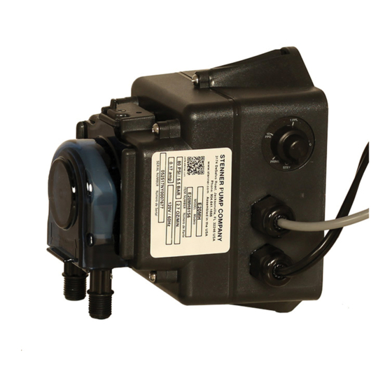
- Page 1 PERISTALTIC METERING PUMPS SINCE 1957 ECON STENNICATOR PERISTALTIC METERING PUMP INSTALLATION AND MAINTENANCE MANUAL W RNING TO BE INSTALLED AND MAINTAINED BY PROPERLY TRAINED PROFESSIONAL INSTALLER ONLY. READ MANUAL & LABELS FOR ALL SAFETY INFORMATION & INSTRUCTIONS.
-
Page 2: Table Of Contents
TABLE OF CONTENTS Warranty and Service Policy ..............3 Safety Instructions........4-6, 11, 12, 16-20, 22-24, 26 Materials of Construction ..............7 Accessories ..................8 Flow Rate Output ................. 9 Operation & Installation..............10-19 Troubleshooting ................20-22 Tube Replacement ................ 23-25 Cleaning the Point of Injection............ - Page 3 WARRANTY AND CUSTOMER SERVICE LIMITED WARRANTY Stenner Pump Company will for a period of one (1) year from the date of purchase (proof of purchase required) repair or replace at our option all defective parts. Stenner is not responsible for any removal or installation costs. Pump tube assemblies and rubber components are considered perishable and are not covered in this warranty.
-
Page 4: Safety Instructions
IMPORTANT SAFETY INSTRUCTIONS When installing and using this electrical equipment, basic safety precautions should always be followed, including the following: 1.READ AND FOLLOW ALL INSTRUCTIONS. 2.WARNING - To reduce the risk of injury, do not permit children to use this product unless they are closely supervised at all times. - Page 5 SAFETY INFORMATION Warns about hazards that CAN cause death, serious personal injury, or property damage if ignored. ELECTRIC SHOCK HAZARD ELECTRIC SHOCK HAZARD Pump supplied with grounding power cord and attached plug. To reduce risk of electrical shock, connect only to a properly grounded, grounding type receptacle. Install only on a circuit protected by a Ground-Fault Circuit-Interrupter (GFCI).
- Page 6 SAFETY INFORMATION continued Warns about hazards that WILL or CAN cause minor personal injury or property damage if ignored. PLUMBING Metering pump installation must always adhere to your local plumbing codes and requirements. Be sure installation does not constitute a cross connection. Check local plumbing codes for guidelines.
-
Page 7: Materials Of Construction
MATERIALS OF CONSTRUCTION All Housings Polycarbonate Pump Tube & Check Valve Duckbill ® Santoprene (FDA approved) Pump Head Rollers Polyethylene Suction/Discharge Tubing & Ferrules Polyethylene (FDA approved) Suction Line Strainer and Cap PVC or Polypropylene (both NSF listed); ceramic weight Tube &... -
Page 8: Accessories
ACCESSORIES Contents 3 Connecting Nuts 1/4" 3 Ferrules 1/4" 1 Duckbill Check Valve 1 Weighted Suction Line Strainer 1/4" 1 20' Roll of Suction/Discharge Tubing 1/4" White 1 Additional Pump Tube 1 Manual Stennicator www.stenner.com... -
Page 9: Flow Rate Output
Pump Number Prefix Tube Assembly per Minute Max. psi per Minute Max. bar E20MH Black 74.0 Approximate Maximum Outputs @ 50/60Hz NOTE: Duckbill check valve included with pumps rated 80 psi (5.5 bar) maximum. Run Time in seconds Setting Simplex... - Page 10 OPERATION The Stennicator requires a signal from a water meter providing a dry contact at a setting of 1PPG, 10 PPG or 1 PPL. It will proportionally dose at a ratio of 1:128 (1 oz. per gallon) to treat process flow rates up to 2.7 gpm .
- Page 11 INSTALLATION ADDITIONAL SAFETY INSTRUCTIONS NOTICE: Indicates special instructions or general mandatory action. Read all safety hazards before installing or servicing the pump. The pump is designed for installation and service by properly trained personnel. Use all required personal protective equipment when working on or near a metering pump.
- Page 12 INSTALLATION continued MOUNT PUMP Select a dry location (to avoid water intrusion and pump damage) above the solution tank. To prevent pump damage in the event of a pump tube leak, never mount the pump vertically with the pump head up. DO NOT mount pump directly over an open solution tank.
- Page 13 INSTALLATION DIAGRAM – RELAY WIRING ECON STENNICATOR Pulse Meter Flow Indicator Controller If applicable Econ Stennicator BLACK BLACK WHITE GREEN ™ ECON STENNICATOR & ECON INTEGRATOR Pulse Meter Flow Indicator Controller ™ ™ Econ Stennicator Econ Integrator Econ Integrator If applicable BLACK BLACK WHITE...
- Page 14 INSTALLATION DIAGRAM – SIMPLEX Grounded Power Outlet: (Grounded-Fault Circuit- Interrupter GFCI) Pump Input Signal Cables Water Meter Output Cable Power Cord Direction of water flow Disassembled view of nut and ferrule Water Meter Shut-Off Valve Suction Line Discharge Line Disassembled View of Duckbill Check Valve Connect Up to 80 psi max.
- Page 15 INSTALLATION DIAGRAM – DUPLEX Grounded Power Outlet: (Grounded-Fault Circuit- Interrupter GFCI) Pump #1 Pump #2 Pump Input Signal Cables Water Meter Output Cable Disassembled Power Cord view of nut and ferrule Direction of water flow Water Meter Shut-Off Valve Suction Line Discharge Line Disassembled View of Duckbill Check Valve...
- Page 16 INSTALLATION continued INSTALL SUCTION LINE TO PUMP HEAD 1. Uncoil the suction/discharge line. Use outside of solution tank as a guide to cut proper length of suction line ensuring it will be 2-3" above the bottom of solution tank. Allow sufficient slack to avoid kinks and stress cracks. Always make a clean square cut to assure that the suction line is burr free.
- Page 17 INSTALLATION continued INSTALL SUCTION WEIGHT TO SUCTION LINE 1. Drill a hole into the bung cap or solution tank lid. Slide the tubing through and secure the weighted strainer to the line. 2. To attach the strainer, push approximately 3.5" of suction line through the cap on the strainer body.
- Page 18 INSTALLATION continued INSTALL DISCHARGE LINE TO PUMP HEAD AND INJECTION POINT 1. Make a secure finger tight connection on the discharge fitting of the pump head as instructed in Install Suction Line instructions. DO NOT use thread sealant tape on pump tube connections or tools to tighten connections.
- Page 19 INSTALLATION continued 4. Hand tighten the injection fitting into the FNPT fitting. Install connecting nut and ferrule to the pump discharge tubing. Insert discharge tubing into injection fitting until it reaches base of fitting. Finger tighten connecting nut to fitting. 5.
-
Page 20: Troubleshooting
TROUBLESHOOTING – DRIVE ASSEMBLY HAZARDOUS VOLTAGE DISCONNECT power before service. Electrical service should be performed by trained personnel only. PROBLEM POSSIBLE CAUSE SOLUTION Noise is excessively loud Lubrication is insufficient Grease gears and gear posts Gears or gear posts are worn Inspect/replace gears and gear posts Drive assembly does not work Electrical supply is faulty... - Page 21 TROUBLESHOOTING – PUMP HEAD PROBLEM POSSIBLE CAUSE SOLUTION Components are cracking Chemical attack Check chemical compatibility Visible fluid in pump head Pump tube rupture/leak Replace pump tube according to instructions No pump output; Depleted solution tank Replenish solution pump head rotates Pump suction line weight is above solution Maintain suction line 2-3"...
- Page 22 TROUBLESHOOTING – PUMP TUBE NOTICE: A leaking pump tube damages the metering pump. Inspect pump frequently for leakage and wear. Refer to Tube Replacement section for additional safety precautions and instructions. PROBLEM POSSIBLE CAUSE SOLUTION Tube leaking Pump tube ruptured Replace pump tube according to instructions Calcium or mineral deposits Clean injection fitting, replace pump tube...
- Page 23 TUBE REPLACEMENT – SAFETY INFORMATION RISK OF EXPOSURE To reduce risk of exposure, check the pump tube regularly for leakage. At the first sign of leakage, replace the pump tube. To reduce risk of exposure, the use of proper personal protective equipment is mandatory when working on or near metering pumps.
-
Page 24: Tube Replacement
TUBE REPLACEMENT PREPARATION 1. Follow all safety precautions prior to tube replacement. 2. Prior to service, pump water or a compatible buffer solution through the pump and suction/discharge line to remove fluid and avoid contact. 3. Turn pump off. 4. Disconnect the suction and discharge connections from pump head. REMOVE TUBE Always unplug pump before doing maintenance work. - Page 25 TUBE REPLACEMENT continued INSTALL NEW TUBE 1. To install new tube, insert one fitting into slot, pull tube around the center of the roller assembly and insert second fitting into the other slot. Illustration D 2. Align tube housing cover with track and slide over tube until fully closed. Illustration E 3.
- Page 26 CLEANING THE POINT OF INJECTION – SAFETY INFORMATION NOTICE: Indicates special instructions or general mandatory action. The duckbill check valve allows the extension tip to be installed in the center of the pipe directly in the flow of water to help reduce deposit accumulation. Warns about hazards that CAN cause death, serious personal injury, or property damage if ignored.
-
Page 27: Cleaning The Point Of Injection
CLEANING THE POINT OF INJECTION continued 1. Turn metering pump off and unplug cord. Disable water pump or auxiliary equipment electrical supply. 2. Depressurize system and bleed pressure from pump discharge line. 3. Loosen and remove connecting nut and ferrule from the duckbill check valve to disconnect discharge tubing: •... - Page 28 CLEANING THE POINT OF INJECTION continued 5. Replace discharge line if cracked or deteriorated. If the end is clogged, cut off the calcified or blocked section of discharge line: • Reassemble the duckbill check valve in reverse order. • Replace ferrule and reinstall the discharge line to the duckbill check valve approximately 3/4"...
- Page 29 EXPLODED VIEW Pump Tube H Gear Kit Drive Assembly Cover Screw Black Roller Assembly Pump Head Cover USA and Canada 800.683.2378, International 904.641.1666 Stennicator...
- Page 30 PARTS DESCRIPTION PART NUMBER Gear Kit EC320 ™ includes spacers, screws & AquaShield Drive Assembly Pad EC302 Black Roller Assembly EC351 Pump Tube H, ferrules 1/4" EC30H-2 2-PK EC30H-5 5-PK Pump Head Cover EC355 Mounting Kit EC303 for Stenner tank or wall mount Stand EC304 for horizontal display or wall mount...
-
Page 31: Mounting Template
MOUNTING TEMPLATE USA and Canada 800.683.2378, International 904.641.1666 Stennicator... - Page 32 STENNER PUMP COMPANY 3174 DeSalvo Road Jacksonville, Florida 32246 USA Phone: 904.641.1666 US Toll Free: 800.683.2378 Fax: 904.642.1012 sales@stenner.com www.stenner.com Hours of Operation (EST): Mon.–Thu. 7:30 am–5:30 pm Fri. 7:00 am–5:30 pm Assembled in the USA © Stenner Pump Company All Rights Reserved IMST 070820...
Need help?
Do you have a question about the E20MH and is the answer not in the manual?
Questions and answers
want to check to make sure the pump is working- but the wires for the water meter and controler are not connected to anything - Can I plug in to electric and ???
The manual does not explicitly state whether the Stenner Pumps E20MH can be plugged in without the water meter and controller wires connected. However, it does provide wiring instructions and safety warnings, including not altering the power cord or plug. To ensure proper operation and avoid potential risks, it is recommended to follow the installation guidelines and connect the necessary wires before powering the pump.
This answer is automatically generated