Table of Contents
Advertisement
Quick Links
Advertisement
Table of Contents

Related Manuals for Stenner Pumps S420 Series


Summary of Contents for Stenner Pumps S420 Series
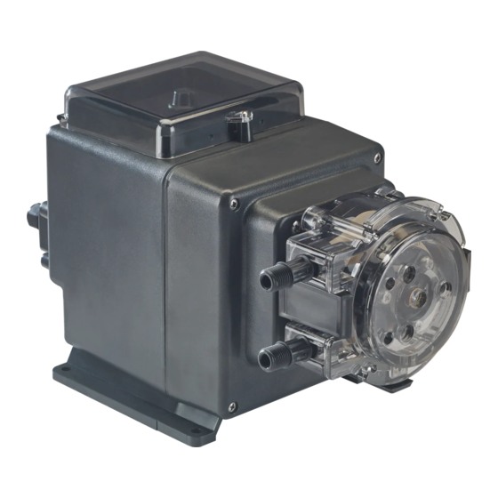
- Page 1 PERISTALTIC METERING PUMPS SINCE 1957 S420 SERIES PERISTALTIC METERING PUMPS INSTALLATION AND MAINTENANCE MANUAL W RNING TO BE INSTALLED AND MAINTAINED BY PROPERLY TRAINED PROFESSIONAL INSTALLER ONLY. READ MANUAL & LABELS FOR ALL SAFETY INFORMATION & INSTRUCTIONS.
-
Page 2: Table Of Contents
TABLE OF CONTENTS Warranty and Service Policy ..............3 Safety Instructions ....4-5, 9, 11-15, 18, 21, 23-27, 30-31, 39, 47 Flow Rate Outputs ................6 Materials of Construction ..............7 Accessories ..................8 Operation ..................9-10 Connections ................. 11-16 Leak Detect.................. - Page 3 WARRANTY AND CUSTOMER SERVICE LIMITED WARRANTY Stenner Pump Company will for a period of two (2) years from the date of purchase (proof of purchase required) repair or replace, at our option, all defective parts. Stenner is not responsible for any removal or installation costs. Pump tube assemblies and rubber components are considered perishable and are not covered in this warranty.
- Page 4 SAFETY INFORMATION IMPORTANT SAFETY INSTRUCTIONS When installing and using this electrical equipment, basic safety precautions should always be followed, including the following: READ AND FOLLOW ALL INSTRUCTIONS Warns about hazards that CAN cause death, serious personal injury, or property damage if ignored. ELECTRIC SHOCK HAZARD RISK OF ELECTRIC SHOCK Connect only to a branch circuit protected by a ground-fault circuit-interrupter (GFCI).
-
Page 5: Safety Instructions
SAFETY INSTRUCTIONS C UTION Warns about hazards that WILL or CAN cause minor personal injury or property damage if ignored. To reduce risk of electric shock, pull plug before servicing this pump. C UTION This pump has been evaluated for use with water only. C UTION Non-submersible pump. -
Page 6: Flow Rate Outputs
FLOW RATE OUTPUTS 25 psi (1.7 bar) max. Turndown Pump Pump Turndown Gallons Gallons Ounces Ounces Liters Liters Milliliters Milliliters Manual Prefix Tube 4-20mA per Day per Hour per Hour per Min. per Day per Hour per Hour per Min. Mode S3403 100:1... -
Page 7: Materials Of Construction
MATERIALS OF CONSTRUCTION All Housings Polycarbonate Pump Tube ® ® S34 Santoprene (FDA approved), or Versilon ® S44, S54 Santoprene (FDA approved) ® ® Check Valve Duckbill S34 Santoprene (FDA approved), or Pellethane Ball Check Valve Components S44, S54 - Ceramic ball (FDA approved); Tantalum spring; FKM seat & O-ring or ®... -
Page 8: Accessories
ACCESSORIES S34 Accessories 3 Connecting Nuts 1/4" & 3 Ferrules 1/4" or 6 mm EUROPE or 3 Connecting Nuts & 2 Adapters 3/8" 1 Injection Fitting 25 psi (1.7 bar) max. or 1 Duckbill Check Valve 100 psi (6.9 bar) max. 1 Weighted Suction Line Strainer 1/4", 3/8"... -
Page 9: Operation
OPERATION OFF: Turn potentiometer fully counterclockwise to CHANGE OPERATING MODE: Set potentiometer to and press MODE button to change between MANUAL and 4-20mA. MANUAL MODE: Turn potentiometer clockwise to increase speed, graduations are approximate. 4-20mA MODE: Turn the potentiometer to maximum flow rate output required at 20 milliamp. Follow instructions for wiring in Connections section. - Page 10 OPERATION continued LED Indicators RUN / STBY / LE K POWER F ULT 4 20mA Manual 4-20m MODE: 25 – 100% Manual MODE: 5 – 100% MODE TO CH NGE OPER TING MODE PL CE PUMP IN OFF ND PRESS MODE BUTTON LED Indicators Solid green When the pump is running and not in drive fault.
-
Page 11: Connections
CONNECTIONS USER INTERFACE CONNECTIONS • The input and output connection terminals are located at the rear of the pump. To access it, unplug the pump and remove the signal cover by taking out the Phillips head screws that secure it in place. •... - Page 12 CONNECTIONS DIAGRAM DIAGRAM Top of Pump Transfer Leak Leak Transfer Relay Relay Detect Detect Relay Relay Relay (b) Relay (a) Connection Terminals 4-20mA Standby Standby − Diagram Leak Detect Sensitivity Adjustment Connection Terminals FACTORY USE ONLY Leak Detect Jumper Rear of the pump with signal cover removed LEAK DETECT JUMPER •...
- Page 13 CONNECTIONS 4-20mA INPUT In 4-20mA mode, the pump’s speed is controlled by a 4-20mA signal input. Pump OHMS Pump signal impedance is 250 ohms. Maximum voltage on the signal line is 36VDC. C UTION Connection Terminals – Connect signal common input to 4-20mA (–), position 11. –...
- Page 14 CONNECTIONS OUTPUT RELAYS The relays are dry contacts, so there is no polarity to observe. The output replays are for signal level only. Maximum rating is for 24VDC at 50mA. Leak Detect Relay • Relay is normally open. • If a leak is detected, this relay will close. •...
- Page 15 CONNECTIONS OUTPUT RELAYS continued Transfer Relay • Relay is Normally Open, when power is applied to the pump, the relay closes. • In the event of a drive fault, a leak, or a loss of power, this relay will open. DO NOT remove Leak Detect Jumper from primary pump.
- Page 16 CONNECTIONS STANDBY INPUT The Standby feature can stop the pump remotely. When a dry contact or open collector signal is received to the Standby inputs, the pump ceases operation as long as the signal is present. In standby, the POWER/STANDBY LED is lit solid red. Controller Pump Input...
-
Page 17: Leak Detect
LEAK DETECT OVERVIEW The leak detect feature alerts if solution is present in the pump head by sensing the conductivity of the liquid. The sensitivity is factory preset to distinguish between water and common water treatment chemicals. Always calibrate the sensitivity with the chemical and chemical concentration utilized in the application to reduce the number of false tube leaks. - Page 18 LEAK DETECT continued CALIBRATE THE LEAK DETECT SENSITIVITY page 1 of 2 TO BE INSTALLED AND MAINTAINED BY PROPERLY TRAINED PROFESSIONAL INSTALLER ONLY. READ MANUAL & LABELS FOR ALL SAFETY INFORMATION & INSTRUCTIONS. Turn off water system, disable all pumps and depressurize the system before performing installation.
- Page 19 LEAK DETECT continued CALIBRATE THE LEAK DETECT SENSITIVITY page 2 of 2 9. Turn the potentiometer an additional one full turn counterclockwise. 10. Remove sponge and thoroughly clean the solution off pins and confirm they are dry. IMPORTANT: Confirm there is no chemical residue remaining on the leak detect pins and bracket.
-
Page 20: Installation
INSTALLATION ADDITIONAL SAFETY INSTRUCTIONS NOTICE: Indicates special instructions or general mandatory action. Read all safety hazards before installing or servicing the pump. The pump is designed for installation and service by properly trained personnel. Use all required personal protective equipment when working on or near a chemical metering pump. - Page 21 INSTALLATION continued MOUNT PUMP Recommended mounting is vertical with pump head pointed downward or horizontal sitting on motor base. Select a dry location (to avoid water intrusion and pump damage) above the solution tank. Best recommended location is above the solution tank in a vertical position with the pump head pointed downward.
- Page 22 INSTALLATION continued DIAGRAM Connect only to a branch circuit protected by a ground-fault-circuit- interrupter (GFCI) Wall Mounting Bracket (requires 2 screws) Suction Line Discharge Line Injection Fitting or Check Valve Shut-Off Valve Solution Tank www.stenner.com S420...
- Page 23 INSTALLATION continued INSTALL SUCTION LINE TO PUMP HEAD 1. Uncoil the suction/discharge line. Use outside of solution tank as a guide to cut proper length of suction line ensuring it will be 2-3" above the bottom of solution tank. Allow sufficient slack to avoid kinks and stress cracks. Always make a clean square cut to assure that the suction line is burr free.
- Page 24 INSTALLATION continued INSTALL SUCTION WEIGHT TO SUCTION LINE 1. Drill a hole into the bung cap or solution tank lid. Slide the tubing through and secure the weighted strainer to the line. 2. To attach the strainer, push approximately 3.5" of suction line through the cap on the strainer body.
- Page 25 INSTALLATION continued INSTALL DISCHARGE LINE TO PUMP HEAD AND INJECTION POINT 1. Make a secure finger tight connection on the discharge fitting of the pump head as instructed in Install Suction Line instructions. DO NOT use thread seal tape on pump tube connections or tools to tighten connections.
- Page 26 INSTALLATION continued 4. Hand tighten the injection fitting into the FNPT fitting. Injection Fitting (S34 – 25 psi max.) 1/4" Slide line through connecting nut and ferrule and insert into injection fitting until it stops. Fingertighten nut. 3/8" Slide line through connecting nut and insert into injection fitting until it stops.
-
Page 27: Troubleshooting
TROUBLESHOOTING MOTOR HAZARDOUS VOLTAGE: DISCONNECT power cord before removing motor cover for service. Electrical service should be performed by trained personnel only. PROBLEM POSSIBLE CAUSE SOLUTION Power LED is not on No power cord connection point Check voltage of receptacle/controller output voltage Failed power supply Return to factory for evaluation... - Page 28 TROUBLESHOOTING PUMP HEAD PROBLEM POSSIBLE CAUSE SOLUTION S34 Roller Assembly will Stripped or cracked roller assembly hub Replace roller assembly not expand or collapse New tube is not relaxed With cover latched, run the roller assembly in with tube housing cover collapsed position for four minutes Components are cracking Depleted solution tank...
- Page 29 TROUBLESHOOTING PUMP HEAD continued PROBLEM POSSIBLE CAUSE SOLUTION Low pump output, Life of roller assembly exhausted Replace roller assembly pump head rotates Life of pump tube exhausted Replace tube according to manual, schedule tube replacement based on application Injection point is restricted Inspect and clean injection point regularly Incorrect tube size or setting Install correct tube size according to manual or...
- Page 30 TROUBLESHOOTING PUMP TUBE NOTICE: A leaking pump tube damages the metering pump. Inspect pump frequently for leakage and wear. Refer to Tube Replacement section for additional safety precautions and instructions. PROBLEM POSSIBLE CAUSE SOLUTION Tube leaking Pump tube ruptured Replace tube according to manual Calcium or mineral deposits Clean injection fitting &...
-
Page 31: Tube Replacement
TUBE REPLACEMENT SAFETY INFORMATION RISK OF CHEMICAL EXPOSURE To reduce risk of exposure, check the pump tube regularly for leakage. At the first sign of leakage, replace the pump tube. To reduce risk of exposure, the use of proper personal protective equipment is mandatory when working on or near chemical metering pumps. - Page 32 S34 TUBE REPLACEMENT continued PREPARATION 1. Follow all safety precautions prior to tube replacement. 2. Prior to service, pump water or a compatible buffer solution through the pump and suction and discharge lines to remove chemical and avoid contact. REMOVE THE PUMP TUBE 1.
- Page 33 S34 TUBE REPLACEMENT continued REMOVE THE PUMP TUBE continued 6. Collapse the roller assembly. Hold the pump body securely, use the tube housing cover as a wrench and quickly (snap) rotate the cover counterclockwise to collapse the roller assembly. The tube will no longer be pressed against the tube housing wall.
- Page 34 S34 TUBE REPLACEMENT continued INSTALL THE TUBE/EXPAND THE ROLLER ASSEMBLY 1. Ensure the power to the pump is off and the input signal is disconnected. 2. Place new tube in the pump head and use your fingers to center it on the rollers. H 3.
- Page 35 S34 TUBE REPLACEMENT continued INSTALL THE TUBE/EXPAND THE ROLLER ASSEMBLY continued IMPORTANT: THE ROLLER ASSEMBLY MUST BE EXPANDED so the tube is pressed against the tube housing wall. 8. Hold the pump securely. Use the cover as a wrench and quickly (snap) rotate the roller assembly clockwise to expand the roller assembly.
- Page 36 S44 & S54 TUBE REPLACEMENT The illustrations show the S5 Pump Head. PREPARATION Rollers 1. Follow all safety precautions prior to tube replacement. Guide Rollers 2. Prior to service, pump water or a compatible buffer solution through the pump and suction and discharge lines to remove chemical and avoid contact.
- Page 37 S44 & S54 TUBE REPLACEMENT continued INSTALL THE TUBE 1. Ensure the input signal is disconnected. 2. Ensure pump is off and control panel cover is closed. 3. Remove tube pull from the holder on the power cord and screw securely onto one tube fitting. E 4.
- Page 38 S44 & S54 TUBE REPLACEMENT continued INSTALL THE TUBE FINAL INSTALLATION 1. Inspect the suction and discharge lines, point of injection, and check valve for blockages. Clean and/or replace as required. Failure to do so may lead to poor pump performance, including shortened tube life.
-
Page 39: Cleaning Point Of Injection
CLEANING POINT OF INJECTION SAFETY INFORMATION NOTICE: Indicates special instructions or general mandatory action. NOTICE: Pumps are supplied with an injection fitting or check valve. All allow the extension tip to be installed in the center of the pipe directly in the flow of water to help reduce deposit accumulation. - Page 40 CLEANING POINT OF INJECTION continued 1. Disconnect power. Disable any water pump or auxiliary equipment's electrical supply. 2. Depressurize system and bleed pressure from pump discharge line. 3. Loosen and remove the 3/8" or 1/4" nut & ferrule from the check valve or injection fitting to disconnect discharge line.
- Page 41 CLEANING POINT OF INJECTION continued 5. Replace discharge line if cracked or deteriorated. If the end is clogged, cut off the calcified or blocked section of discharge line. Injection Fitting Replace ferrule and reinstall the discharge line to the injection fitting approximately 3/4"-1"...
-
Page 42: Parts
PUMP HEAD PARTS S34 Pump Head Parts DESCRIPTION PART NUMBER S3400-1 S3QP Tube Housing with plastic latches 2-PK S3400-2 S3500-1 S3QP Roller Assembly 4-PK S3500-4 S3600-1 S3QP Tube Housing Cover with bushing 4-PK S3600-4 Latches, plastic 2-PK QP401-2 S44 Pump Head Parts DESCRIPTION PART NUMBER S44B0-1... - Page 43 PUMP HEADS Refer to the FLOW RATE OUTPUTS chart to match the pump with the correct tube. S34 Pump Heads 25 psi (1.7 bar) max. Includes pump head with tube, ferrules 1/4" or Europe 6 mm Insert tube # for DESCRIPTION PART NUMBER Europe 6 mm...
- Page 44 PUMP HEAD SERVICE KITS Pump Head Service Kit Contents QP , S3QP Roller Assembly, Tube, Nuts 1/4", Ferrules 1/4" or 6 mm, Latches S4, S5 Roller Assembly, Tube, Nuts 3/8" Refer to the FLOW RATE OUTPUTS chart to match the pump with the correct tube. S34 Pump Head Service Kits 25 psi (1.7 bar) max.
- Page 45 PUMP TUBES Refer to the FLOW RATE OUTPUTS chart to match the pump with the correct tube. S34 Tubes Includes ferrules 1/4" or Europe 6 mm Insert tube # for DESCRIPTION PART NUMBER Europe 6 mm 2-PK UCCP20 UCCP2 CE ®...
- Page 46 CHECK VALVES S34 Duckbill Check Valves 100 psi (6.9 bar) max. DESCRIPTION PART NUMBER Europe 6 mm UCDBINJ UCINJCE 1/4" or 6 mm Duckbill Check Valve with nut, ferrule, ® Santoprene duckbill 5-PK MCDBINJ MCINJCE UCTYINJ UCTINJCE 1/4" or 6 mm Duckbill Check Valve with nut, ferrule, ®...
-
Page 47: Chemical Resistance Guide
CHEMICAL RESISTANCE GUIDE Ratings Key – Chemical Effect A Fluid has minor or no effects C Fluid has severe effects B Fluid has minor to moderate effects No data available • C UTION The information is provided ONLY as a guide to assist in determining chemical compatibility for wetted components. - Page 48 CHEMICAL RESISTANCE GUIDE continued Stainless Versilon ® LDPE Silicone Tantalum Santoprene ® Chemical / Solution Steel EPDM Calcium Hypochlorite 5% • Calcium Salts • • • Carbon Disulfide • • Carbon Tetrachloride • Castor Oil • • • Chlorine see Sodium Hypochlorite Chloroacetic Acid •...
- Page 49 CHEMICAL RESISTANCE GUIDE continued Stainless Chemical / Solution Versilon ® LDPE Silicone Tantalum Santoprene ® Steel EPDM Iodine Lactic Acid Lead Acetate • Linseed Oil • Limonene • • Lubricating Oils • • Magnesium Chloride Magnesium Hydroxide • Magnesium Sulfate Malic Acid •...
- Page 50 CHEMICAL RESISTANCE GUIDE continued Stainless Versilon ® LDPE Silicone Tantalum Santoprene ® Chemical / Solution Steel EPDM Silicone Oil • Silver Nitrate • Soap Solutions • Sodium • • • • Sodium Bisulfate • • Sodium Bisulfite • Sodium Borate •...
-
Page 51: Wall Mounting Bracket Dimensions
WALL MOUNTING BRACKET DIMENSIONS 1/4" 5" 1/4" NOTICE: Leave 8" of clearance above pump to allow for removal from mounting bracket. USA and Canada 800.683.2378, International 904.641.1666 S420... - Page 52 STENNER PUMP COMPANY 3174 DeSalvo Road Jacksonville, Florida 32246 USA Phone: 904.641.1666 US Toll Free: 800.683.2378 Fax: 904.642.1012 sales@stenner.com www.stenner.com Hours (EST) Mon.–Fri. 7:00 am–8:00 pm Assembled in the USA with US and international components © Stenner Pump Company All Rights Reserved IMS4 032024a...
Need help?
Do you have a question about the S420 Series and is the answer not in the manual?
Questions and answers