Stenner Pumps 45MHP2 Series Installation And Maintenance Manual
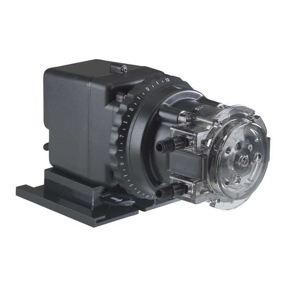
Classic series output metering pump
Hide thumbs
Also See for 45MHP2 Series:
- Installation and maintenance manual (100 pages) ,
- Installation and maintenance manual (50 pages) ,
- Installation and maintenance manual (50 pages)

Related Manuals for Stenner Pumps 45MHP2 Series


Summary of Contents for Stenner Pumps 45MHP2 Series
- Page 1 CLASSIC SERIES INSTALLATION AND MAINTENANCE MANUAL PERISTALTIC METERING PUMPS SINCE 1957...
-
Page 2: Table Of Contents
TABLE OF CONTENTS WARRANTY AND SERVICE POLICY ..........3 SAFETY INFORMATION......4-5, 16-18, 21-25, 29, 32, 36 PUMP IDENTIFICATION ............6-7 OUTPUTS ................ 8-13 MATERIALS OF CONSTRUCTION ..........14 ACCESSORY CHECKLIST............15 INSTALLATION ..............16-24 TROUBLESHOOTING ............25-28 TUBE REPLACEMENT ............30-35 CLEANING THE POINT OF INJECTION ........ - Page 3 WARRANTY AND CUSTOMER SERVICE LIMITED WARRANTY Stenner Pump Company will for a period of one (1) year from the date of purchase (proof of purchase required) repair or replace – at our option – all defective parts. Stenner is not responsible for any removal or installation costs.
- Page 4 SAFETY INFORMATION Warns about hazards that CAN cause death, serious personal injury, or property damage if ignored. ELECTRIC SHOCK HAZARD: Pump supplied with grounding power cord and attached plug. To reduce risk of electrical shock, connect only to a properly grounded, grounding type receptacle. Install only on a circuit protected by a Ground-Fault Circuit-Interrupter (GFCI).
- Page 5 SAFETY INFORMATION continued Warns about hazards that WILL or CAN cause minor personal injury or property damage if ignored. PLUMBING: Chemical feed pump installation must always adhere to your local plumbing codes nd requirements. Be sure installation does not constitute a cross connection. Check local plumbing codes for guidelines.
-
Page 6: Pump Identification
PUMP IDENTIFICATION BOX LABEL 85MHP5 85MJH1A1STAA 02010503943 100 (6.9) 5 Adjustable (18.9 Ajustable) 1/4" White (1/4" Blanco) www.stenner.com... - Page 7 PUMP IDENTIFICATION continued DATA LABEL 85MHP5 85MJH1A1STAA 100 psi / 6.9 bar 120V 60Hz 1.7 amp 5 gpd / 18.9 lpd 02010503943 WARNING LABEL NOTE: Agency listings vary by model. USA and Canada 800.683.2378, International 904.641.1666...
-
Page 8: Outputs
OUTPUTS 45 SERIES ADJUSTABLE OUTPUT – APPROXIMATE GPD @ 60Hz MAXIMUM PUMP TUBE FEED RATE CONTROL SETTING MODEL PRESSURE NUMBER 45MHP2* 100 psi (6.9 bar) 0.6 0.9 45M1 25 psi (1.7 bar) 45MHP10* 100 psi (6.9 bar) 2.0 3.0 9.0 10.0 45M2 25 psi (1.7 bar) 45MHP22* 100 psi (6.9 bar) - Page 9 OUTPUTS 85 SERIES ADJUSTABLE OUTPUT – APPROXIMATE GPD @ 60Hz MAXIMUM PUMP TUBE FEED RATE CONTROL SETTING MODEL PRESSURE NUMBER 85MHP5* 100 psi (6.9 bar) 1.0 1.5 85M1 25 psi (1.7 bar) 85MHP17* 100 psi (6.9 bar) 3.4 5.1 8.5 10.2 11.9 13.6 15.3 17.0 85M2 25 psi (1.7 bar) 85MHP40* 100 psi (6.9 bar)
- Page 10 OUTPUTS 100 SERIES ADJUSTABLE OUTPUT – APPROXIMATE GPD @ 60Hz MAXIMUM PUMP TUBE FEED RATE CONTROL SETTING MODEL PRESSURE NUMBER 100DMHP5* 100 psi (6.9 bar) 1.2 1.8 100DM1 25 psi (1.7 bar) 100DMHP20* 100 psi (6.9 bar) 4.0 6.0 8.0 10.0 12.0 14.0 16.0 18.0 20.0 100DM2 25 psi (1.7 bar) 100DM3...
- Page 11 OUTPUTS 170 SERIES ADJUSTABLE OUTPUT – APPROXIMATE GPD @ 60Hz MAXIMUM PUMP TUBE FEED RATE CONTROL SETTING MODEL PRESSURE NUMBER 170DMHP9* 100 psi (6.9 bar) 2.0 3.0 9.0 10.0 170DM1 25 psi (1.7 bar) 170DMHP34* 100 psi (6.9 bar) 6.0 9.5 13.6 17.0 20.4 23.8 27.2 30.6 34.0 170DM2 25 psi (1.7 bar) 170DM3...
- Page 12 OUTPUTS 100MDC SERIES DETERMINING OUTPUT FOR DUAL HEAD DUAL CONTROL MODEL • The dial ring is labeled L-10; L = 5%, 1-10 indicates approximately 10% of maximum output. • Setting #10 on both feed rate controls will deliver the pump’s maximum output. •...
- Page 13 OUTPUTS 170MDC SERIES DETERMINING OUTPUT FOR DUAL HEAD DUAL CONTROL MODEL • The dial ring is labeled L-10; L = 5%, 1-10 indicates approximately 10% of maximum output. • Setting #10 on both feed rate controls will deliver the pump’s maximum output. •...
-
Page 14: Materials Of Construction
MATERIALS OF CONSTRUCTION All Housings Polycarbonate Peristaltic Tube & Check Valve Duckbill Santoprene ® , FDA approved Peristaltic Tube Tygothane ® , FDA approved Check Valve Duckbill † Pellathane ® Suction/Discharge Tubing & Ferrules (1/4" & 6 mm) Polyethylene, FDA approved Weighted Suction Line Strainer Polypropylene or Type 1 Rigid PVC body with Type 1 Rigid PVC cap, NSF listed;... -
Page 15: Accessory Checklist
ACCESSORY CHECKLIST PRE-INSTALLATION 25 psi Accessory Kit Contents 3 Connecting Nuts 1/4" or 3/8" 3 Ferrules 1/4" & 6 mm Europe OR 2 Ferrules 3/8" 1 Injection Fitting 1 Weighted Suction Line Strainer 1/4", 3/8", 6 mm Europe 1 20' Roll of Suction/Discharge Tubing 1/4"... -
Page 16: Installation
INSTALLATION ADDITIONAL SAFETY INSTRUCTIONS NOTICE: Indicates special instructions or general mandatory action. Read all safety hazards before installing or servicing the pump. The pump is designed for installation and service by properly trained personnel. Use all required personal protective equipment when working on or near a chemical metering pump. - Page 17 INSTALLATION continued MOUNT PUMP Select a dry location (to avoid water intrusion and pump damage) above the solution tank. Best recommended location is above the solution tank in a vertical position with the pump head pointed downward and the spill recovery (see page 20) in place to reduce the risk and severity of damage.
- Page 18 INSTALLATION continued ADDITIONAL INSTRUCTIONS FOR CE PUMPS ADDITIONAL INSTALLATION INSTRUCTIONS All Class II Pumps located in Zone 1 of swimming pool areas require locating where flooding cannot occur. This pump is intended to be installed as “fixed” as opposed to portable. The Rain Roof must be installed and “vertical orientation”...
-
Page 19: Installation Diagram
INSTALLATION DIAGRAM Rain Roof slides into wall mounting bracket Always use Rain Roof for outdoor (no tools necessary). use or if metering pump is subject to washdowns. On/Off Switch Grounded (under roof, not Power Outlet; visible this view) protected by Ground-Fault Circuit- Interrupter... - Page 20 INSTALLATION continued SPILL RECOVERY Mount the pump vertically and use the spill recovery to drain chemical back to the tank in the event of tube failure. This will help prevent chemical from collecting in the tube housing and reduces spillage on the floor. The pump motor is ventilated and water intrusion can cause motor damage.
- Page 21 INSTALLATION continued INSTALL SUCTION LINE TO PUMP HEAD 1. Uncoil the suction/discharge tubing. Use outside of solution tank as a guide to cut proper length of suction line ensuring it will be 2-3" above the bottom of solution tank. Allow sufficient slack to avoid kinks and stress cracks. Always make a clean square cut to assure that the suction line is burr free.
- Page 22 INSTALLATION continued INSTALL SUCTION WEIGHT TO SUCTION LINE 1. Drill a hole into the bung cap or solution tank lid. Slide the tubing through and secure the weighted strainer to the line. 2. To attach the strainer, push approximately 3.5" of suction line through the cap on the strainer body.
- Page 23 INSTALLATION continued INSTALL DISCHARGE LINE TO PUMP HEAD AND INJECTION POINT 1. Make a secure finger tight connection on the discharge fitting of the pump head as instructed in Install Suction Line instructions. DO NOT use thread seal tape on pump tube connections or tools to tighten connections.
- Page 24 INSTALLATION continued 4. Hand tighten the injection fitting into the FNPT fitting. 0-25 psi Model (includes injection fitting) Install connecting nut and ferrule to the pump discharge line. Insert discharge line into injection fitting until it reaches base of fitting. Finger tighten connecting nut to fitting.
-
Page 25: Troubleshooting
TROUBLESHOOTING – MOTOR HAZARDOUS VOLTAGE: DISCONNECT power cord before removing motor cover for service. Electrical service should be performed by trained personnel only. PROBLEM POSSIBLE CAUSE SOLUTION Loud or excessive noise Worn ball bearings Replace rotor assembly Insufficient lubrication Apply AquaShield ®... - Page 26 TROUBLESHOOTING – FEED RATE CONTROL PROBLEM POSSIBLE CAUSE SOLUTION ® Adjustment ring will not turn Seized variable cam Apply Aquashield to variable cam & cam slot Seized adjustment ring Clean then lubricate ring with AquaShield ® Adjustment ring turns, Variable cam disengaged from ring Re-insert 90˚...
- Page 27 TROUBLESHOOTING – PUMP HEAD PROBLEM POSSIBLE CAUSE SOLUTION Components cracking Chemical attack Check chemical compatibility Pump head leaking Pump tube rupture Replace pump tube, ferrules; center tube No pump output, Depleted solution tank Replenish solution pump head rotates Pump suction line weight is Position suction line 3"...
- Page 28 TROUBLESHOOTING – PUMP TUBE NOTICE: A leaking pump tube damages the metering pump. Inspect pump frequently for leakage and wear. Refer to Tube Replacement section for additional safety precautions and instructions. PROBLEM POSSIBLE CAUSE SOLUTION Tube leaking Pump tube ruptured Replace pump tube, ferrules;...
-
Page 29: Tube Replacement
TUBE REPLACEMENT – SAFETY INFORMATION RISK OF CHEMICAL EXPOSURE To reduce risk of exposure, check the pump tube regularly for leakage. At the first sign of leakage, replace the pump tube. To reduce risk of exposure, the use of proper personal protective equipment is mandatory when working on or near chemical metering pumps. - Page 30 TUBE REMOVAL Illustrated Basic Steps NOTICE: Refer to written instructions for complete steps. Adjustable Model Adjustable model must be on setting 10 Open latches Remove cover Invert cover 3 Lugs Cover Tube Fittings Center of Roller Assembly Cover Feet Align cover feet near tube fittings Collapse roller assembly Remove tube Check rollers...
- Page 31 TUBE INSTALLATION & CENTERING Illustrated Basic Steps NOTICE: Refer to written instructions for complete steps. 3 Lugs Center of Roller Assembly Place new tube Align cover feet near the bottom Cover Expand roller assembly Confirm roller assembly is expanded Cover Feet Cover Bushing ®...
- Page 32 TUBE REPLACEMENT – SINGLE HEAD Adjustable & Fixed Output Pumps PREPARATION 1. Follow all safety precautions prior to tube replacement. 2. Prior to service, pump water or a compatible buffer solution through the pump and suction and discharge lines to remove chemical and avoid contact. REMOVE THE PUMP TUBE 1.
- Page 33 TUBE REPLACEMENT – SINGLE HEAD Adjustable & Fixed Output Pumps INSTALL THE PUMP TUBE AND EXPAND THE ROLLER ASSEMBLY 1. Ensure the power to the pump is off and the power cord is unplugged. On the adjustable model, ensure that the feed rate control is set to 10. Illustration A p30 2.
- Page 34 TUBE REPLACEMENT – SINGLE HEAD Adjustable & Fixed Output Pumps 8. Expand roller assembly. Adjustable Model • Hold the feed rate control securely, use the cover as a wrench and quickly (snap) rotate the roller assembly clockwise to expand the roller assembly. The tube will be pressed against the tube housing wall.
- Page 35 TUBE REPLACEMENT – SINGLE HEAD Adjustable & Fixed Output Pumps CENTER THE TUBE 1. Ensure the pump is off. Lift the latch located between the tube fittings, leaving the end of the latch engaged with the lip on the tube housing cover. Leave the latch on the opposite side engaged.
-
Page 36: Cleaning The Point Of Injection
CLEANING THE POINT OF INJECTION – SAFETY INFORMATION NOTICE: Indicates special instructions or general mandatory action. NOTICE: 0-25 psi models are installed using an injection fitting and 26-100 psi models use an injection check valve. Both allow the extension tip to be installed in the center of the pipe directly in the flow of water to help reduce deposit accumulation. - Page 37 CLEANING THE POINT OF INJECTION continued 1. Turn metering pump off and unplug cord. Disable water pump or auxiliary equipment electrical supply. 2. Depressurize system and bleed pressure from pump discharge line. 3. Loosen and remove connecting nut and ferrule from the injection check valve or injection fitting to disconnect discharge tubing.
- Page 38 CLEANING THE POINT OF INJECTION continued 5. Replace discharge line if cracked or deteriorated. If the end is clogged, cut off the calcified or blocked section of discharge line. 0-25 psi Model (includes injection fitting) Replace ferrule and reinstall the discharge line to the injection fitting approximately 3/4"-1"...
- Page 39 MOTOR EXPLODED VIEW Power Cord Rain Roof Rotor Assembly with Bearings, Brackets, Motor Cover with Cord Gear Post Tolerance Rings & Fan Metal Reduction Gear Strain Relief Bushing Phenolic Gear Cover Screw B Coil Screw G w/Lock Washer On-Off Switch Plate Coil Motor Shaft Thrust Washer...
- Page 40 MOTOR Pressure Spring Motor (Adjustable Models Only) Motor Base MOTOR 50Hz International MOTOR 60Hz PART NUMBER PART NUMBER For Adjustable Output 45 & 100 Series For Adjustable Output 45 & 100 Series 120V PM6041D 230V PM64230 220V PM6042D 250V PM6426D For Adjustable Output 85 &...
- Page 41 MOTOR SERVICE KITS Wire Nuts Coil Ground Screw E Phenolic Gear Motor with Spacer AquaShield ® Coil Shaft with Coil Screw G Gear with Lock Washer Metal Reduction Rotor Assembly & Fan Gear Posts Cover Screw B Gear MOTOR SERVICE KITS GEAR CASE SERVICE KITS PART NUMBER PART NUMBER...
- Page 42 FEED RATE CONTROL EXPLODED VIEW FRC Screw A Variable Cam Index Spider Index Pin Lifter Feed Rate Housing Mounting Rivet Index Pin Spring Index Pin Main Shaft Single Head/Adjustable Feed Rate Index Pin Holder Index Plate O-Ring Seal Output Mounting Plate Dial Ring Roller Clutch Main Shaft...
- Page 43 FEED RATE CONTROL AND SERVICE KIT AquaShield ® Index Plate Screw A Lifter Variable Cam FEED RATE CONTROL WITH SHAFT FEED RATE CONTROL SERVICE KIT PART NUMBER PART NUMBER For Adjustable Output Single Head FSK100 45 & 85 Series FC5040D For Adjustable Output Double Head 100 &...
- Page 44 PUMP HEAD EXPLODED VIEW Tube Housing Roller Assembly Pump Tube Tube Housing Cover Contact factory for part numbers. www.stenner.com...
- Page 45 PUMP HEAD Pump Tube Pressure Rating PUMP TUBE 0-25 psi (0-1.7 bar) 26-100 psi (1.8-6.9 bar) NUMBER Check valve required Classic Single Head ONLY PART NUMBER Includes Santoprene ® pump tube, ferrules 1/4" QP25__–1 select tube # from 1, 2, 3, 4, 5 for __ QP25__–2 2-PK Includes Santoprene...
- Page 46 PUMP HEAD SERVICE KITS Pump Tube Pressure Rating PUMP TUBE 0-25 psi (0-1.7 bar) 26-100 psi (1.8-6.9 bar) NUMBER Check valve required Classic Single Head ONLY Ferrules 1/4" Ferrules 1/4" Latches Latches or 6 mm or 6 mm Europe Europe Roller Assembly Roller Assembly Connecting Nuts 1/4"...
-
Page 47: Pump Tubes
PUMP TUBES Pump Tube Pressure Rating PUMP TUBE 0-25 psi (0-1.7 bar) 26-100 psi (1.8-6.9 bar) NUMBER Check valve required Tube number located on fitting Classic Single Head ONLY PART NUMBER Santoprene ® pump tube, ferrules 1/4" UCCP20__ 2-PK select tube # from 1, 2, 3, 4, 5, 7 for __ MCCP20__ 5-PK Santoprene... -
Page 48: Check Valves
CHECK VALVES Injection Check Valve 1/4" Injection Check Valve 3/8" Injection Check Valve 6 mm FOR 26-100 psi (1.8-6.9 bar) PUMPS PART NUMBER Includes Santoprene ® duckbill, ferrule 1/4" UCDBINJ MCDBINJ 5-PK Includes Santoprene ® duckbill, ferrule 3/8" UCINJ38 MCINJ38 5-PK Includes Pellathane ®*... -
Page 49: For Your Records
FOR YOUR RECORDS Model Serial Number Date of Installation USA and Canada 800.683.2378, International 904.641.1666... - Page 50 STENNER PUMP COMPANY 3174 DeSalvo Road Jacksonville, Florida 32246 Phone: 904.641.1666 US Toll Free: 800.683.2378 Fax: 904.642.1012 sales@stenner.com www.stenner.com Hours of Operation (EST): Mon.–Thu. 7:30 am–5:30 pm Fri. 7:00 am–5:30 pm Stenner products are proudly made in the USA © Stenner Pump Company All Rights Reserved CMQ0811a...
- Page 51 SERIE CLASICA MANUAL DE INSTALACION Y MANTENIMIENTO DOSIFICADORES PERISTALTICOS DESDE 1957...
- Page 52 TABLA DE CONTENIDO GARANTIA Y NORMAS DE SERVICIO..........3 INFORMACION DE SEGURIDAD ....4-5, 16-18, 21-25, 29, 32, 36 IDENTIFICACION DEL DOSIFICADOR .......... 6-7 CAUDALES................ 8-13 MATERIALES DE CONSTRUCCION ..........14 LISTA DE CHEQUEO DE ACCESORIOS ......... 15 INSTALACION..............16-24 GUIA DE REPARACION DE AVERIAS ........
- Page 53 GARANTIA Y NORMAS DE SERVICIO GARANTIA LIMITADA Stenner Pump Company cambiará o reparará (nuestra opción) todo producto defectuoso por un año desde el momento de compra (se requiere comprobante/recibo de compra). Stenner no es responsable por los costos de cambio y reemplazo de partes. Tubos de bombeo y otras partes de goma son partes de desgaste y no están cubiertos bajo la garantía.
- Page 54 INSTRUCCIONES DE SEGURIDAD Este símbolo le advierte de potencial peligro que puede causarle muerte o serios daños a su persona o propiedad si lo ignora. RIESGO DE DESCARGA ELECTRICA: Este dosificador incluye un cable eléctrico con conductor a tierra y enchufe apropiado.
- Page 55 INSTRUCCIONES DE SEGURIDAD Este símbolo le advierte de potencial peligro que puede causarle menores daños a su persona o propiedad si lo ignora. PLOMERIA: La instalación del dosificador debe seguir los códigos y requerimientos de plomería locales. Asegúrese de no provocar una conexión cruzada. Verifique sus códigos de instalación locales por más información.
- Page 56 IDENTIFICACION DEL DOSIFICADOR ETIQUETA SITUADA EN LA CAJA 85MHP5 85MJH1A1STAA 02010503943 100 (6.9) 5 Adjustable (18.9 Ajustable) 1/4" White (1/4" Blanco) www.stenner.com...
- Page 57 IDENTIFICACION DEL DOSIFICADOR ETIQUETA DE DATOS 85MHP5 85MJH1A1STAA 100 psi / 6.9 bar 120V 60Hz 1.7 amp 5 gpd / 18.9 lpd 02010503943 ETIQUETA DE PRECAUCIONES NOTA: Los sellos de certificación de agencias varían por modelo. USA y Canadá 800.683.2378, Internacional 904.641.1666...
- Page 58 CAUDALES DE LA SERIE 45 CAUDAL AJUSTABLE – CAUDAL APROXIMADO EN GPD @ 60Hz Presión No. de Posición del controlador de caudal Modelo Máxima Tubo 45MHP2 100 psi (6.9 bar) 0.6 0.9 45M1 25 psi (1.7 bar) 45MHP10 100 psi (6.9 bar) 2.0 3.0 9.0 10.0 45M2...
- Page 59 CAUDALES DE LA SERIE 85 CAUDAL AJUSTABLE – CAUDAL APROXIMADO EN GPD @ 60Hz Presión No. de Posición del controlador de caudal Modelo Máxima Tubo 85MHP5 100 psi (6.9 bar) 1.0 1.5 85M1 25 psi (1.7 bar) 85MHP17 100 psi (6.9 bar) 3.4 5.1 8.5 10.2 11.9 13.6 15.3 17.0 85M2...
- Page 60 CAUDALES DE LA SERIE 100 CAUDAL AJUSTABLE – CAUDAL APROXIMADO EN GPD @ 60Hz Presión No. de Posición del controlador de caudal Modelo Máxima Tubo 100DMHP5 100 psi (6.9 bar) 1.2 1.8 100DM1 25 psi (1.7 bar) 100DMHP20 100 psi (6.9 bar) 4.0 6.0 8.0 10.0 12.0 14.0 16.0 18.0 20.0 100DM2...
- Page 61 CAUDALES DE LA SERIE 170 CAUDAL AJUSTABLE – CAUDAL APROXIMADO EN GPD @ 60Hz Presión No. de Posición del controlador de caudal Modelo Máxima Tubo 170DMHP9 100 psi (6.9 bar) 2.0 3.0 9.0 10.0 170DM1 25 psi (1.7 bar) 170DMHP34 100 psi (6.9 bar) 6.0 9.5 13.6 17.0 20.4 23.8 27.2 30.6 34.0 170DM2...
- Page 62 CAUDALES DE LA SERIE 100MDC COMO DETERMINAR EL CAUDAL DE UN DOSIFICADOR DE DOBLE CABEZAL Y DOBLE CONTROLADOR • El controlador de caudal está marcado L-10. L = 5%, 1 al 10 indican incrementos aproximados del 10% del caudal máximo. •...
- Page 63 CAUDALES DE LA SERIE 170MDC COMO DETERMINAR EL CAUDAL DE UN DOSIFICADOR DE DOBLE CABEZAL Y DOBLE CONTROLADOR • El controlador de caudal está marcado L-10. L = 5%, 1 al 10 indican incrementos aproximados del 10% del caudal máximo. •...
- Page 64 MATERIALES DE CONSTRUCCION Todas las carcasas Policarbonato Tubo peristáltico & goma de válvula de inyección Santoprene ®* , aprobado por FDA Tubo peristáltico Tygothane ®** , aprobado por FDA Goma de válvula de inyección Pellathane ®† Tubo de succión y descarga y casquillos (1/4" & 6 mm) Polietileno, aprobado por FDA Filtro de succión con pesa Polipropileno;...
- Page 65 LISTA DE CHEQUEO DE ACCESORIOS CHEQUEE PREVIO A LA INSTALACION El kit de accesorios de 25 psi (1.7 bar) contiene lo siguiente 3 Tuercas de Conexión de 1/4" o 3/8" 3 Casquillos con 1/4" o 6 mm Europa o 2 Casquillos con 3/8" 1 Conexión de Inyección 1 Filtro con Pesa de Succión 1/4", 3/8"...
- Page 66 INSTALACION INSTRUCCIONES DE SEGURIDAD ADICIONALES NOTICE: Este símbolo indica instrucciones especiales o mandatorias a seguir. Lea todas las instrucciones y advertencias de seguridad antes de instalar o reparar su dosificador. Este dosificador ha sido diseñado para ser instalado por profesionales entrenados. Asegúrese de utilizar el equipamiento protectivo necesario cuando se encuentre trabajando en o cerca de un dosificador de químicos.
- Page 67 INSTALACION MONTAJE DEL DOSIFICADOR Seleccione una localidad seca (para evitar la intrusión de agua y daño al dosificador) por arriba del tanque de químico. La mejor ubicación es por encima del tanque de químico en posición vertical con el cabezal hacia abajo y el tubo de recuperación opcional de vertidos conectado, para reducir riesgo y severidad de daños si ocurre una pérdida (ver página 20 por detalles).
- Page 68 INSTALACION INSTRUCCIONES ADICIONALES PARA DOSIFICADORES CON SELLO DE CE (EUROPA) ADDITIONAL INSTALLATION INSTRUCTIONS All Class II Pumps located in Zone 1 of swimming pool areas require locating where flooding cannot occur. This pump is intended to be installed as “fixed” as opposed to portable. The Rain Roof must be installed and “vertical orientation”...
- Page 69 DIAGRAMA DE INSTALACION El techo de lluvia se desliza en el soporte de Siempre utilice techo de lluvia para uso pared sin el uso de herramientas a la intemperie o si el dosificador está sujeto a caídas de agua. Receptáculo con conexión a tierra Interruptor “on/off”...
- Page 70 El tubo de recuperación de pérdidas, permite que el químico regrese al tanque. El agujero parcial se perfora con un destormillador #2 Phillips. Utilice un trozo de tubo de succión y descarga de 1/4" e inserte en la perforación. Tubo de recuperación de pérdidas 3"...
- Page 71 INSTALACION INSTALE EL TUBO DE SUCCION AL CABEZAL DEL DOSIFICADOR 1. Desenrolle el tubo de succión y descarga. Corte la sección de tubo que necesite teniendo en cuenta que el tubo debe quedar a 7-8 cm del fondo del tanque. Mida el largo por fuera del tanque para asegurarse que el corte sea apropiado.
- Page 72 INSTALACION INSTALACION DEL FILTRO CON PESA AL TUBO DE SUCCION 1. Perfore un agujero en la tapa o cubierta del tanque de químico. Deslice el tubo de succión en el mismo y conecte el filtro con pesa en el extremo. 2.
- Page 73 INSTALACION INSTALE EL TUBO DE DESCARGA, CONECTE AL CABEZAL DEL DOSIFICADOR Y AL PUNTO DE INYECCION 1. Realice la conexión a mano del tubo de descarga al extremo del tubo de bombeo correspondiente, como se indicó previamente en la instalación de tubo de succión y descarga.
- Page 74 INSTALACION 4. Enrosque a mano el conector de la válvula a la conexión hembra de 1/4 o 1/2 pulgada. Modelos de 0 a 1.7 bar de presión (incluyen conector de inyección) Deslice tuerca y casquillo en el tubo de descarga. Inserte el tubo en el conector de inyección hasta llegar al tope.
- Page 75 GUIA RAPIDA DE REPARACION DE AVERIAS – MOTOR PELIGRO DE SHOCK ELECTRICO: DESENCHUFE el cable eléctrico antes de remover la cubierta del motor para repararlo. Reparaciones deben ser hechas por personal entrenado. PROBLEMA POSIBLE CAUSA SOLUCION El motor es Cojinete de bolas desgastado Cambie el montaje de cojinete del motor excesivamente ruidoso Insuficiente lubricación...
- Page 76 GUIA RAPIDA DE REPARACION DE AVERIAS – CONTROLADOR DE CAUDAL PROBLEMA POSIBLE CAUSA SOLUCION ® Anillo regulador no gira Leva variable trancada Lubrique con Aquashield la leva y ranura de la leva Cuadrante/anillo trancado Limpie y lubrique el cuadrante/anillo Anillo gira, Leva se ha separado del cuadrante Inserte la punta en ángulo recto en el orificio caudal no cambia...
- Page 77 GUIA RAPIDA DE REPARACION DE AVERIAS – CABEZAL PROBLEMA POSIBLE CAUSA SOLUCION Componentes están quebrados Daño químico Verifique compatibilidad del químico Pérdida en el cabezal Rotura del tubo de bombeo Cambie tubo y casquillos; centre el tubo Conjunto de rodillos rotan, El tanque de químico está...
- Page 78 GUIA RAPIDA DE REPARACION DE AVERIAS – TUBO DE BOMBEO NOTICE: Un tubo de bombeo con pérdida causa daño al dosificador. Inspeccione el mismo con frecuencia por pérdidas y desgaste. Refiérase a la sección de reemplazo de tubos por indicaciones y precauciones adicionales. PROBLEMA POSIBLE CAUSA SOLUCION...
- Page 79 CAMBIO DE TUBOS – INSTRUCCIONES DE SEGURIDAD RIESGO DE CONTACTO QUIMICO Para reducir el riesgo de exposición a químicos, chequee el tubo de bombeo regularmente por pérdidas. A la primera señal de pérdida, cambie el tubo de bombeo. Para reducir el riesgo de exposición a químicos, es mandatorio el uso de un equipo protectivo apropiado cuando esté...
- Page 80 EXTRACCION DE TUBO Pasos Básicos Ilustrados NOTICE: Haga referencia a las instrucciones escritas para obtener detalles completos. Modelos de caudal ajustable deben tener Abra los sujetadores el anillo del caudal en 10 Remueva la tapa De vuelta la tapa 3 Remaches Tapa Conexiones del tubo Pies de...
- Page 81 INSTALACION Y CENTRADO DE TUBO Pasos Básicos Ilustrados NOTICE: Haga referencia a las instrucciones escritas para obtener detalles completos. 3 Remaches Pies de la tapa Centro del conjunto de rodillos Instale el tubo nuevo Alinee la tapa del cabezal como se muestra Tapa Expanda el conjunto de rodillos Confirme el conjunto de rodillos...
- Page 82 CAMBIO DE TUBO – DOSIFICADORES DE UN CABEZAL Dosificadores de Caudal Ajustable y Fijo Preparación 1. Siga todas las precauciones de seguridad antes de cambiar el tubo. 2. Antes de realizar el servicio, bombee una cantidad generosa de agua o solución neutral para limpiar todo residuo químico y evitar el contacto.
- Page 83 CAMBIO DE TUBO – DOSIFICADORES DE UN CABEZAL Dosificadores de Caudal Ajustable y Fijo Instale el tubo y expanda el conjunto de rodillos 1. Asegúrese que el dosificador no esté conectado. En los modelos de caudal ajustable, verifique que el anillo de caudal esté ubicado en el 10. Ilustración A, p.30 2.
- Page 84 CAMBIO DE TUBO – DOSIFICADORES DE UN CABEZAL Dosificadores de Caudal Ajustable y Fijo 8. Expanda el conjunto de rodillos. Modelos de Caudal Ajustable • Sujete el controlador de caudal, use la tapa como herramienta y gire la misma de forma rápida (con un movimiento corto y veloz), en dirección del reloj, para expandir los rodillos.
- Page 85 CAMBIO DE TUBO – DOSIFICADORES DE UN CABEZAL Dosificadores de Caudal Ajustable y Fijo Centre el Tubo 1. Asegúrese el dosificador está apagado. Levante la parte trasera del sujetador que se encuentra entre las conexiones de tubos, dejando la parte delantera del mismo enganchada en el labio de la carcasa.
- Page 86 LIMPIEZA DEL PUNTO DE INYECCION – INSTRUCCIONES DE SEGURIDAD NOTICE: Este símbolo indica instrucciones especiales o mandatorias a seguir. NOTICE: Modelos de 0 a 1.7 bar son instalados utilizando una conexión de inyección. Para modelos de 0 a 6.9 bar se utiliza una válvula de inyección. Ambos permiten que la punta del conector de inyección se instale en el medio de la tubería, directamente en el flujo de agua;...
- Page 87 USA y Canadá 800.683.2378, Internacional 904.641.1666...
- Page 88 LIMPIEZA DEL PUNTO DE INYECCION 5. Reemplace el tubo de descarga si el mismo está roto o desgastado. Si la punta está tapada, corte la misma. Modelos de 0 a 1.7 bar (incluyen conector de inyección) Reemplace el casquillo y reinstale el tubo de descarga al conector introduciendo el mismo hasta encontrar el tope (3/4 a 1 pulgada).
- Page 89 DIAGRAMA DETALLADO DEL MOTOR Cable Eléctrico Techo de Lluvia Conjunto de Rotor con Cubierta de Cojinetes, Soportes, Anillos Motor con Cable Poste de Engranaje de Tolerancia y Ventilador Bujes de Relevo de Presión Engranaje Reductor Engranaje Fenólico Tornillo de Cubierta B Tornillo de Bobina G con Arandela Placa de Interruptor...
- Page 90 MOTOR Resorte de Presión Motor (En Modelos de Caudal Ajustable Solamente) Base de Motor MOTOR 50Hz Internacional MOTOR 60Hz NO. DE PARTE NO. DE PARTE Para Dosificadores de Caudal Ajustable Para Dosificadores de Caudal Ajustable Series 45 y 100 Series 45 y 100 120V PM6041D 230V...
- Page 91 KITS DE SERVICIO DEL MOTOR Conector de Cables Engranaje Fenólico con Separador Engranaje Grasa AquaShield ® Bobina de Motor con Eje Tornillo de Bobina G Con Arandela Engranaje Reductor Conjunto de Rotor y Ventilador Tornillo B KITS DE SERVICIO DEL MOTOR KIT DE SERVICIO DE ENGRANAJES NO.
- Page 92 DIAGRAMA DETALLADO DEL CONTROLADOR DE CAUDAL Tornillo de Controlador A Leva Variable Araña de Indicación Levantador de Clavija Carcasa de Controlador de Indicación Remache de Resorte de Montaje Indicación Clavija de Indicación Eje Principal – un Cabezal y Cubierta de Sujetador de Clavija Plato Indicador Anillo Sellador...
- Page 93 CONTROLADOR DE CAUDAL Y KIT DE SERVICIO ® Grasa AquaShield Plato Indicador Tornillos A Levantador de Clavija Leva Variable CONTROLADORES DE CAUDAL CON EJE KIT DE SERVICIO DEL CONTROLADOR DE CAUDAL NO. DE PARTE NO. DE PARTE Para Series 45 y 85 de un Cabezal y Caudal Ajustable FSK100 FC5040D...
- Page 94 DIAGRAMA DETALLADO DEL CABEZAL DEL DOSIFICADOR Carcasa del Cabezal Conjunto de Rodillos Tubo de Bombeo Cubierta del Cabezal Contacte la fábrica por números de partes. www.stenner.com...
- Page 95 CABEZAL DEL DOSIFICADOR Indice de Presión de Tubo NUMERO 0-1.7 bar 1.8-6.9 bar DE TUBO Requiere válvula de inyección SOLAMENTE para dosificadores de serie clásica de un cabezal NO. DE PARTE Incluye tubo de Santoprene ® y casquillos de 1/4" QP25__–1 seleccione no.
- Page 96 KITS DE SERVICIO DEL CABEZAL Indice de Presión de Tubo NUMERO 0-1.7 bar 1.8-6.9 bar DE TUBO Requiere válvula de inyección SOLAMENTE para dosificadores de serie clásica de un cabezal Casquillos 1/4" o Sujetadores Casquillos 1/4" o Sujetadores 6 mm para Europa 6 mm para Europa Conjunto de Rodillos Conjunto de Rodillos...
- Page 97 TUBOS DE BOMBEO Indice de Presión de Tubo NUMERO 0-1.7 bar 1.8-6.9 bar DE TUBO Requiere válvula de inyección Número de Tubo localizado SOLAMENTE para dosificadores de serie clásica de un cabezal en la conexión NO. DE PARTE Tubo de bombeo Santoprene ®...
- Page 98 VALVULAS DE INYECCION Válvula de Inyección de 1/4 de Pulgada Válvula de Inyección de 3/8 de Pulgada Válvula de Inyección de 6 mm PARA DOSIFICADORES DE ALTA PRESION 26-100 psi (1.8-6.9 bar) NO. DE PARTE Incluye goma de válvula de inyección de Santoprene ®...
- Page 99 PARA SUS RECORDS Modelo Número de Serial Fecha de Instalación USA y Canadá 800.683.2378, Internacional 904.641.1666...
- Page 100 STENNER PUMP COMPANY 3174 DeSalvo Road Jacksonville, Florida 32246 Tel: 904.641.1666 Línea gratuita (USA y Canadá): 800.683.2378 Fax: 904.642.1012 sales@stenner.com www.stenner.com Horas de Funcionamiento (GMT-05:00/Costa Este USA y Canadá): Lunes a Jueves de 7:30 a 17:00 Viernes de 7:00 a 12:00 mediodía Los productos Stenner son fabricados en los Estados Unidos de América ©...
Need help?
Do you have a question about the 45MHP2 Series and is the answer not in the manual?
Questions and answers