
Related Manuals for Stenner Pumps E10T1F


Summary of Contents for Stenner Pumps E10T1F
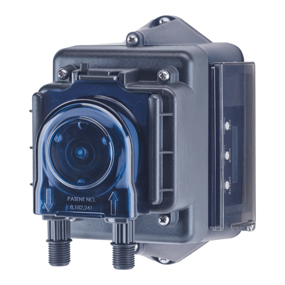
- Page 1 ECON SERIES T PUMP INSTALLATION AND MAINTENANCE MANUAL PERISTALTIC METERING PUMPS SINCE 1957...
-
Page 2: Table Of Contents
TABLE OF CONTENTS Warranty and Service Policy ..............3 Safety Information........4-6, 9, 12, 14-15, 17-21, 23-26 Materials of Construction ..............7 Accessory Checklist ................8 Outputs ....................9 Operation Description ..............10-11 Programming ................12-13 Installation................... 14-20 Troubleshooting ................21-23 Tube Replacement ................ - Page 3 WARRANTY AND CUSTOMER SERVICE LIMITED WARRANTY Stenner Pump Company will for a period of one (1) year from the date of purchase (proof of purchase required) repair or replace – at our option – all defective parts. Stenner is not responsible for any removal or installation costs.
-
Page 4: Important Safety Instructions
IMPORTANT SAFETY INSTRUCTIONS When installing and using this electrical equipment, basic safety precautions should always be followed, including the following: 1.READ AND FOLLOW ALL INSTRUCTIONS. 2.WARNING - To reduce the risk of injury, do not permit children to use this product unless they are closely supervised at all times. -
Page 5: Safety Information
SAFETY INFORMATION Warns about hazards that CAN cause death, serious personal injury, or property damage if ignored. ELECTRIC SHOCK HAZARD ELECTRIC SHOCK HAZARD: The pump must only be used with the Class II power supply that is supplied with the pump. RISQUE DE CHOC ELECTRIQUE: La pompe ne peut être utilisée qu’avec le bloc d’alimentation de type Classe II originalement fourni avec celle-ci. - Page 6 SAFETY INFORMATION continued Warns about hazards that WILL or CAN cause minor personal injury or property damage if ignored. PLUMBING: Metering pump installation must always adhere to your local plumbing codes and requirements. Be sure installation does not constitute a cross connection. Check local plumbing codes for guidelines.
-
Page 7: Materials Of Construction
MATERIALS OF CONSTRUCTION All Housings Polycarbonate Peristaltic Tube & Check Valve Duckbill ®* Santoprene , FDA approved Suction/Discharge Tubing & Ferrules Polyethylene, FDA approved Weighted Suction Line Strainer Polypropylene or Type 1 Rigid PVC body with Type 1 Rigid PVC cap, NSF listed; ceramic weight Tube Fittings Polypropylene, NSF listed Check Valve Fittings... -
Page 8: Accessory Checklist
ACCESSORY CHECKLIST Contents 3 Connecting Nuts 1/4" 3 Ferrules 1/4" or 6 mm Europe 1 Injection Fitting or Injection Check Valve 1 Weighted Suction Line Strainer 1/4" 1 20' Roll of Suction/Discharge Tubing 1/4" White or UV Black OR 6 mm White Europe 1 Additional Pump Tube 1 Installation Manual Econ T... -
Page 9: Outputs
OUTPUTS GALLONS & OUNCES LITERS & MILLILITERS Injection check valve is included with pump rated 26-80 psi (1.8-5.5 bar). USA and Canada 800.683.2378, International 904.641.1666 Econ T... -
Page 10: Operation Description
OPERATION DESCRIPTION CONTROL PANEL The pump features a control panel with an LCD display; when operating it will display the current day, time, and the pump mode of operation; either AUTO, ON or OFF. The display has indicators that represent the days of the week, operating mode and the event (timer). -
Page 11: Operation Description
OPERATION DESCRIPTION continued CLOCK The clock uses a 24-hour format for programming and can be set when the pump is not plugged in. 24-hr 12-hr 24-hr 12-hr 00:00 12 midnight 12:00 Noon 01:00 1 a.m. 13:00 1 p.m. 02:00 2 a.m. 14:00 2 p.m. -
Page 12: Programming
PROGRAMMING FIRST TIME USE NOTICE: Indicates special instructions or general mandatory action. Before programming for the first time, the control panel must be reset to the default settings. Press and hold the buttons simultaneously CLOCK TIMER for 5 seconds. The clock will display 00:00 and the timers will be disabled. 1. - Page 13 PROGRAMMING continued 3. SET ADDITIONAL TIMERS: TIMER 02 THROUGH 24, AS NEEDED Press the button and repeat the above steps for each timer. TIMER When finished setting the desired timers, press the button to return to the CLOCK operating display. NOTE: DO NOT overlap timer programs.
-
Page 14: Installation
INSTALLATION ADDITIONAL SAFETY INSTRUCTIONS NOTICE: Indicates special instructions or general mandatory action. Read all safety hazards before installing or servicing the pump. The pump is designed for installation and service by properly trained personnel. Use all required personal protective equipment when working on or near a metering pump. - Page 15 INSTALLATION continued MOUNT PUMP Select a dry location (to avoid water intrusion and pump damage) above the solution tank. To prevent pump damage in the event of a pump tube leak, never mount the pump vertically with the pump head up. DO NOT mount pump directly over an open solution tank.
-
Page 16: Installation Diagram
INSTALLATION DIAGRAM Grounded Power Outlet: (Grounded-Fault Circuit- Interrupter GFCI) Discharge Suction Disassembled view of Connecting Nut & Ferrule Disassembled View Injection Injection Check Valve Fitting Suction Line 26-80 psi 0-25 psi Discharge Duckbill Line Injection Check Valve or Injection Fitting Flow direction of solution Solution Tank... - Page 17 INSTALLATION continued INSTALL SUCTION LINE TO PUMP HEAD 1. Uncoil the suction/discharge line. Use outside of solution tank as a guide to cut proper length of suction line ensuring it will be 2-3" above the bottom of solution tank. Allow sufficient slack to avoid kinks and stress cracks. Always make a clean square cut to assure that the suction line is burr free.
- Page 18 INSTALLATION continued INSTALL SUCTION WEIGHT TO SUCTION LINE 1. Drill a hole into the bung cap or solution tank lid. Slide the tubing through and secure the weighted strainer to the line. 2. To attach the strainer, push approximately 3.5" of suction line through the cap on the strainer body.
- Page 19 INSTALLATION continued INSTALL DISCHARGE LINE TO PUMP HEAD AND INJECTION POINT 1. Make a secure finger tight connection on the discharge fitting of the pump head as instructed in Install Suction Line instructions. DO NOT use thread sealant tape on pump tube connections or tools to tighten connections.
-
Page 20: Installation
INSTALLATION continued 4. Hand tighten the injection fitting into the FNPT fitting. Install connecting nut and ferrule to the pump discharge tubing. Insert discharge tubing into injection fitting until it reaches base of fitting. Finger tighten connecting nut to fitting. 5. -
Page 21: Troubleshooting
TROUBLESHOOTING – DRIVE ASSEMBLY HAZARDOUS VOLTAGE: DISCONNECT power before service. Electrical service should be performed by trained personnel only. PROBLEM POSSIBLE CAUSE SOLUTION Noise is excessively loud Lubrication is insufficient Grease gears and gear posts Gears or gear posts are worn Inspect/replace gears and gear posts Drive assembly does not work Electrical supply is faulty... - Page 22 TROUBLESHOOTING – PUMP HEAD PROBLEM POSSIBLE CAUSE SOLUTION Components are cracking Incompatibility with fluid Check compatibility Visible fluid in pump head Pump tube rupture/leak Replace pump tube and ferrules No pump output; Depleted solution tank Replenish solution pump head rotates Pump suction line weight is above solution Maintain suction line 2-3"...
-
Page 23: Troubleshooting
TROUBLESHOOTING – PUMP TUBE NOTICE: A leaking pump tube damages the metering pump. Inspect pump frequently for leakage and wear. Refer to Tube Replacement section for additional safety precautions and instructions. PROBLEM POSSIBLE CAUSE SOLUTION Tube leaking Pump tube ruptured Replace pump tube and ferrules Calcium or mineral deposits Clean injection fitting, replace pump tube... - Page 24 TUBE REPLACEMENT – SAFETY INFORMATION RISK OF EXPOSURE To reduce risk of exposure, check the pump tube regularly for leakage. At the first sign of leakage, replace the pump tube. To reduce risk of exposure, the use of proper personal protective equipment is mandatory when working on or near metering pumps.
-
Page 25: Tube Replacement
TUBE REPLACEMENT PREPARATION 1. Follow all safety precautions prior to tube replacement. 2. Prior to service, pump water or a compatible buffer solution through the pump and suction and discharge lines to remove fluid and avoid contact. 3. Unplug the pump. 4. - Page 26 TUBE REPLACEMENT continued REMOVE TUBE Always unplug pump before doing maintenance work. 1. Unplug the pump. 2. Remove the Phillips head locking screw on the latch (CE models only). Slide the vertical tab 180 degrees from left to right to unlock the cover latch. Illustration A 3.
- Page 27 TUBE REPLACEMENT continued INSTALL NEW TUBE 1. To install new tube, insert one fitting into slot, pull tube around the center of the roller assembly and insert second fitting into the other slot. Illustration D 2. Align tube housing cover with track and slide over tube until fully closed. Illustration E 3.
-
Page 28: Exploded View
EXPLODED VIEW Pump Head Cover Gear Kit Drive Assembly Pad Drive Assembly Cover Screw White Roller Black Roller Assembly Assembly (pump tubes G, H) (pump tubes A, B, C, F) Pump Tube Econ T www.stenner.com... - Page 29 PARTS DESCRIPTION PART NUMBER DC Motor, brushed with leads (not shown) E10 Series only EC300 E20 Series only EC307 ® Gear Kit includes spacers, screws & Aquashield E10 Series only EC310 E20 Series only EC320 Drive Assembly Pad EC302 White Roller Assembly (pump tubes A,B,C, F only) EC350 Black Roller Assembly (pump tubes G,H only) EC351...
-
Page 30: For Your Records
FOR YOUR RECORDS Model Serial Number Date of Installation Econ T www.stenner.com... -
Page 31: Mounting Template
MOUNTING TEMPLATE USA and Canada 800.683.2378, International 904.641.1666 Econ T... - Page 32 STENNER PUMP COMPANY 3174 DeSalvo Road Jacksonville, Florida 32246 Phone: 904.641.1666 US Toll Free: 800.683.2378 Fax: 904.642.1012 sales@stenner.com www.stenner.com Hours of Operation (EST): Mon.–Thu. 7:30 am–5:30 pm Fri. 7:00 am–5:30 pm Stenner products are proudly made in the USA © Stenner Pump Company All Rights Reserved IMET 0812b...
- Page 33 DOSIFICADOR SERIE ECON T MANUAL DE INSTALACION Y MANTENIMIENTO DOSIFICADORES PERISTALTICOS DESDE 1957...
- Page 34 TABLA DE CONTENIDO Garantía y Normas de Servicio ............. 3 Información de Seguridad ....... 4-6, 9, 12, 14-15, 17-21, 23-26 Materiales de Construcción ..............7 Lista de Verificación de Accesorios ............8 Caudales ..................... 9 Descripción del Funcionamiento............ 10-11 Programación ................12-13 Instalación ...................
- Page 35 GARANTIA Y SERVICIO AL CLIENTE GARANTIA LIMITADA Por un período de un (1) año de la fecha de compra (se exige comprobante de compra), Stenner Pump Company reparará o reemplazará, a su criterio, todas las piezas defectuosas. Stenner no es responsable de los costos de retiro o instalación. Los conjuntos de tubos de bombeo y los componentes de goma se consideran piezas de desgaste y no están cubiertos por esta garantía.
- Page 36 INSTRUCCIONES IMPORTANTES DE SEGURIDAD Cuando instale y use este equipo eléctrico, debe seguir precauciones básicas de seguridad, incluídas las siguientes: 1.LEA Y SIGA TODAS LAS INSTRUCCIONES. 2.ADVERTENCIA - Para reducir el riesgo de lesiones, no permita que los niños usen este producto, a menos que en todo momento estén supervisados muy de cerca.
-
Page 37: Información De Seguridad
INFORMACION DE SEGURIDAD Advierte sobre peligros que PUEDEN causar la muerte, lesiones personales graves o daño a la propiedad si se le ignora. PELIGRO DE DESCARGA ELECTRICA PELIGRO DE DESCARGA ELECTRICA: Solo deberá usar el dosificador con la fuente de alimentación Clase II que se suministra con el dosificador. - Page 38 INFORMACION DE SEGURIDAD continuación Advierte sobre peligros que PUEDEN causar o que CAUSARÁN lesiones personales menores o daño a la propiedad si se les ignora. TUBERIAS: La instalación del dosificador siempre debe cumplir con sus códigos y requisitos de tubería locales. Asegúrese de que la instalación no sea una conexión cruzada. Revise directrices en sus códigos de tuberías locales..
-
Page 39: Materiales De Construcción
MATERIALES DE CONSTRUCCION Todas las carcasas Policarbonato Tubo peristático y goma de válvula de inyección ®* Santoprene , aprobados por la FDA Tubo de succión y descarga y casquillos Polietileno, aprobados por la FDA Filtro de succión con pesa Polipropileno o cuerpo de PVC rígido tipo 1 con tapa de PVC rígido tipo 1, con certificación de la NSF;... -
Page 40: Lista De Verificación De Accesorios
LISTA DE VERIFICACION DE ACCESORIOS Contenidos 3 Tuercas de conexión de 1/4" 3 Casquillos de 1/4" o 6 mm Europa 1 Conexión de inyección o válvula de inyección 1 Filtro de succión con pesa de 1/4" 1 Rollo de 20' pies de tubo de succión y descarga 1/4"... -
Page 41: Caudales
CAUDALES GALONES & ONZAS Prefijo Del Tubo Bombeo de Artículo LITROS & MILILITROS Prefijo Del Tubo Bombeo de Artículo Válvula de inyección incluída con dosificadores clasificados de 1.8 a 5.5 bar. EE. UU. y Canadá 1.800.683.2378, Internacional +1.904.641.1666 Econ T... -
Page 42: Descripción Del Funcionamiento
DESCRIPCION DEL FUNCIONAMIENTO PANEL DE CONTROL El dosificador incluye un panel de control con una pantalla de LCD; cuando está funcionando, presenta la fecha, la hora y el modo de funcionamiento del dosificador; ya sea AUTO (AUTOMATICO), ON (ENCENDIDO) o OFF (APAGADO). Esta pantalla tiene indicadores que representan los días de la semana, el modo de funcionamiento y el evento (temporizador). - Page 43 OPERATION DESCRIPTION continuación RELOJ El reloj usa un formato de 24 horas para programación y se puede fijar cuando no está enchufado el dosificador. 24 horas 12 horas 24 horas 12 horas 00:00 12 de media noche 12:00 Medio día 01:00 1 a.m.
-
Page 44: Programación
PROGRAMACION USO POR PRIMERA VEZ AVISO: Indica instrucciones especiales o acción obligatoria general. Antes de programar el dosificador por primera vez, se deberá reiniciar el panel de control a los parámetros predeterminados. Mantenga presionados simultáneamente los botones durante 5 segundos. El reloj CLOCK TIMER mostrará... - Page 45 PROGRAMACION continuación 3. FIJAR TEMPORIZADORES ADICIONALES: TIMER 02 AL 24, SEGUN SE NECESITE Presione el botón y repita los pasos anteriores para cada temporizador. TIMER Cuando termine de ajustar los temporizadores deseados, presione el botón CLOCK para regresar a la pantalla de funcionamiento. NOTA: NO traslape los programas del temporizador.
-
Page 46: Instalación
INSTALACION INSTRUCCIONES DE SEGURIDAD ADICIONALES AVISO: Indica instrucciones especiales o acción obligatoria general. Lea todas las precauciones de seguridad antes de instalar o realizar servicio en el dosificador. El dosificador está diseñado para que personal debidamente entrenado lo instale y revise. Utilice todo el equipo de protección personal requerido al trabajar en un dosificador o cerca del mismo. - Page 47 INSTALACION continuación MONTAJE DEL DOSIFICADOR Seleccione un lugar seco (para evitar daños por intrusión de agua y daño en el dosificador) sobre el tanque de solución. Para evitar daños en el dosificador en caso de una pérdida del tubo de bombeo, nunca monte el dosificador de forma vertical con el cabezal hacia arriba.
- Page 48 DIAGRAMA DE INSTALACION Tomacorriente con conexión a tierra: (Interruptor accionado por corriente de pérdida a tierra GFCI) Descarga Succión Vista de la tuerca de conexión y el casquillo desarmados Vista de la unidad desarmada Válvula de Conexión inyección de inyección Tubo de succión 26-80 psi 0-25 psi...
- Page 49 INSTALACION continuación INSTALE EL TUBO DE SUCCION AL CABEZAL DEL DOSIFICADOR 1. Desenrosque el tubo de succión y descarga. Utilice el exterior del tanque de solución como una guía para cortar la longitud adecuada de tubo de succión, asegurando que quede a 5-7cm del fondo del tanque.
- Page 50 INSTALACION continuación INSTALE EL FILTRO CON PESA AL TUBO DE SUCCION 1. Perfore un orificio en la tapa o cubierta del tanque de solución. Deslice el tubo de succión en el mismo y conecte el filtro con pesa al tubo. 2.
- Page 51 INSTALACION continuación INSTALE EL TUBO DE DESCARGA AL CABEZAL Y AL PUNTO DE INYECCION 1. Realice una conexión segura con los dedos en el extremo de descarga del cabezal del dosificador como se indica en las instrucciones Instale el tubo de succión. NO use cinta aisladora de rosca en las conexiones del tubo de bombeo o herramientas para apretar las conexiones.
- Page 52 INSTALACION continuación 4. Enrosque a mano la conexión de inyección a la conexión FNPT de la tubería. Deslice la tuerca de conexión y casquillo en la tubería de descarga. Inserte la tubería de descarga en la conexión de inyección hasta llegar al tope. Apriete la tuerca con los dedos en la conexión.
- Page 53 SOLUCION DE PROBLEMAS – MOTOR VOLTAJE PELIGROSO: DESCONECTE la corriente antes de realizar servicio. Sólo personal entrenado debe realizar el servicio eléctrico. PROBLEMA POSIBLE CAUSA SOLUCION Ruido demasiado fuerte No es suficiente la lubricación Engrase los engranajes y los postes de engranaje Engranajes o postes de Inspeccione/cambie los engranajes y...
-
Page 54: Solución De Problemas
SOLUCION DE PROBLEMAS – CABEZAL DEL DOSIFICADOR PROBLEMA POSIBLE CAUSA SOLUCION Agrietamiento de Incompatibilidad con el fluido Verifique la compatibilidad los componentes Fluido visible en el cabezal Ruptura/filtración del tubo de bombeo Cambie el tubo y los casquillos del dosificador El dosificador no tiene Tanque de solución vacío Reabastezca la solución... - Page 55 SOLUCION DE PROBLEMAS – TUBO DE DOSIFICACION AVISO: Las pérdidas en el tubo de bombeo dañan el dosificador. Inspeccione el dosificador con frecuencia para detectar pérdidas o desgaste. Consulte la sección Cambio de tubo para leer precauciones de seguridad e instrucciones adicionales. PROBLEMA POSIBLE CAUSA SOLUCION...
- Page 56 CAMBIO DEL TUBO – INFORMACION DE SEGURIDAD RIESGO DE EXPOSICION Para reducir el riesgo de exposición, revise periódicamente el tubo de bombeo para detectar si presenta pérdidas. A la primera señal de pérdida, cambie el tubo. Para reducir el riesgo de exposición, el uso de equipo de protección personal es obligatorio al trabajar en o cerca de dosificadores.
-
Page 57: Cambio De Tubos
CAMBIO DE TUBOS PREPARACION 1. Siga todas las precauciones de seguridad antes de cambiar el tubo. 2. Antes de realizar servicio, dosifique agua o una solución neutralizadora compatible a través del dosificador y los tubos de succión y descarga para eliminar los fluidos y evitar contacto. - Page 58 CAMBIO DE TUBOS continuación RETIRE EL TUBO Siempre desconecte el dosificador antes de efectuar trabajos de mantenimiento. 1. Desconecte el dosificador. 2. Retire el tornillo de traba Phillips del ajustador del cabezal (solo modelos CE). Deslice la lengueta vertical 180 grados de izquierda a derecha para desbloquear el ajustador de la cubierta.
- Page 59 CAMBIO DE TUBOS continuación INSTALE UN TUBO NUEVO 1. Para instalar un tubo nuevo, inserte un extremo en la ranura, jale el tubo alrededor del centro del conjunto de rodillos e inserte el segundo extremo en la otra ranura. Ilustración D 2.
- Page 60 DIAGRAMA ESQUEMATICO Tapa del cabezal del dosificador Kit de engranajes Almohadilla del motor Motor Tornillo de la tapa Conjunto de Conjunto de rodillos blanco rodillos negro (tubo de (tubos de bombeo bombeo G, H) Tubo de bombeo A, B, C, F) Econ T www.stenner.com...
- Page 61 PARTES NUMERO DESCRIPCION DE PARTE Motor CC con escobillas (no se muestra) Solo Serie E10 EC300 Solo Serie E20 EC307 ® Kit de engranajes incluye espaciadores, tornillos & Aquashield Solo Serie E10 EC310 Solo Serie E20 EC320 Almohadilla del motor EC302 Conjunto de rodillos blanco (solo tubo de bombeo A, B, C, F) EC350...
-
Page 62: Para Su Registro
PARA SU REGISTRO Modelo Número de Serial Fecha de instalación Econ T www.stenner.com... -
Page 63: Plantilla De Montaje
PLANTILLA DE MONTAJE EE. UU. y Canadá 1.800.683.2378, Internacional +1.904.641.1666 Econ T... - Page 64 STENNER PUMP COMPANY 3174 DeSalvo Road Jacksonville, Florida 32246 Teléfono: +1.904.641.1666 Línea gratuita en EE. UU.: 1.800.683.2378 Fax: +1.904.642.1012 sales@stenner.com www.stenner.com Horario de atención (GMT–05:00. Costa este USA): Lunes a jueves de 7:30 a.m. a 5:30 p.m. Viernes, de 7:00 a.m. a 5:30 p.m. Los productos Stenner son fabricados en los Estados Unidos ©...
Need help?
Do you have a question about the E10T1F and is the answer not in the manual?
Questions and answers