Table of Contents
Advertisement
Quick Links
Advertisement
Table of Contents

Related Manuals for Stenner Pumps ECON LD Series


Summary of Contents for Stenner Pumps ECON LD Series
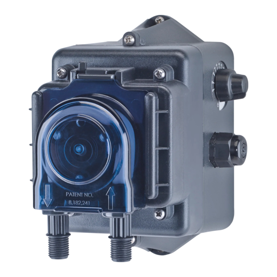
- Page 1 PERISTALTIC METERING PUMPS SINCE 1957 ECON LD PUMP SERIES PERIS TALTIC ME TERING PUMP I N S TA L L AT I O N A N D M A I N T E N A N C E M A N U A L WARNING TO BE INSTALLED AND MAINTAINED BY PROPERLY TRAINED PROFESSIONAL INSTALLER ONLY.
-
Page 2: Table Of Contents
TABLE OF CONTENTS Warranty and Service Policy ................ 3 Safety Instructions ........... 4-6, 9-12, 14-18, 20-22, 24 Materials of Construction ................7 Accessories ....................8 Flow Rate Outputs ..................9 Installation ..................10-17 Troubleshooting .................. 18-20 Tube Replacement ................21-23 Cleaning the Point of Injection............ -
Page 3: Warranty And Customer Service
WARRANT Y AND CUSTOMER SERVICE LIMITED WARRANTY Stenner Pump Company will for a period of one (1) year from the date of purchase (proof of purchase required) repair or replace at our option all defective parts. Stenner is not responsible for any removal or installation costs. Pump tube assemblies and rubber components are considered perishable and are not covered in this warranty. -
Page 4: Safety Instructions
IMPORTANT SAFET Y INSTRUCTIONS When installing and using this electrical equipment, basic safety precautions should always be followed, including the following: 1. READ AND FOLLOW ALL INSTRUCTIONS. 2. WARNING - To reduce the risk of injury, do not permit children to use this product unless they are closely supervised at all times. -
Page 5: Safety Information
SAFET Y INFORMATION Warns about hazards that CAN cause death, serious personal injury, or property damage if ignored. ELECTRIC SHOCK HAZARD VAC MODELS ONLY ELECTRIC SHOCK HAZARD Pump supplied with grounding power cord and attached plug. To reduce risk of electrical shock, connect only to a properly grounded, grounding type receptacle. - Page 6 SAFET Y INFORMATION continued Warns about hazards that WILL or CAN cause minor personal injury or property damage if ignored. PLUMBING Metering pump installation must always adhere to your local plumbing codes and requirements. Be sure installation does not constitute a cross connection. Check local plumbing codes for guidelines.
-
Page 7: Materials Of Construction
MATERIALS OF CONSTRUCTION All Housings Polycarbonate Pump Tube Santoprene (FDA approved) ® Pump Head Rollers Polyethylene Check Valve Duckbill Santoprene ® (FDA approved) or FKM (NSF approved) Suction/Discharge Lines & Ferrules Polyethylene (FDA approved) Suction Line Strainer and Cap PVC or Polypropylene (both NSF listed); ceramic weight Tube &... -
Page 8: Accessories
ACCESSORIES 3 Connecting Nuts 1/4" 3 Ferrules 1/4" or 6 mm Europe 1 Duckbill Check Valve 1 Weighted Suction Line Strainer 1/4" or 6 mm Europe 20' Suction/Discharge Line 1/4", white or UV black or 20' Suction/Discharge Line, white, 6 mm Europe 1 Additional Pump Tube 1 Manual Econ LD... -
Page 9: Flow Rate Outputs
FLOW RATE OUTPUTS Item Number Pump Roller Approximate Ounces Pressure Milliliters Pressure Prefix Tube Assembly Turndown Ratio per Hour Max. psi per Hour Max. bar E10LHM White 50:1 0.04–2.4 1.3–70.0 E10LHF White 50:1 0.11–8.1 3.2–240.0 E10LHG Black 50:1 0.50–25.1 14.8–742.3 E10LHH Black 50:1... -
Page 10: Installation
INSTALLATION ADDITIONAL SAFETY INSTRUCTIONS NOTICE: Indicates special instructions or general mandatory action. Read all safety hazards before installing or servicing the pump. The pump is designed for installation and service by properly trained personnel. Use all required personal protective equipment when working on or near a metering pump. - Page 11 INSTALLATION continued MOUNT PUMP Select a dry location (to avoid water intrusion and pump damage) above the solution tank. To prevent pump damage in the event of a pump tube leak, never mount the pump vertically with the pump head up. DO NOT mount pump directly over an open solution tank.
- Page 12 Declaration of Conformity INSTALLATION Standards Used for Conformity Testing and Certification: continued EN60335-1 EN55014-1 EN61000-3-3 EN60335-2-41 EN61000-3-2 EN62233 ADDITIONAL INSTRUCTIONS FOR CE PUMPS ADDITIONAL INSTALLATION INSTRUCTIONS 1. All Class II Pumps located in Zone 1 of swimming pool areas require locating where flooding cannot occur. 2.
-
Page 13: Installation Diagram
INSTALLATION DIAGRAM Grounded Power Outlet: (Grounded-Fault Circuit- Interrupter GFCI) Suction Disassembled View of Duckbill Check Valve 80 psi max. Discharge Duckbill Suction Line Disassembled view of nut and ferrule Discharge Line Flow direction of solution Shut-Off Valve Solution Tank Econ LD USA and Canada 800.683.2378, International 904.641.1666... - Page 14 INSTALLATION continued INSTALL SUCTION LINE TO PUMP HEAD 1. Uncoil the suction/discharge line. Use outside of solution tank as a guide to cut proper length of suction line ensuring it will be 2-3" above the bottom of solution tank. Allow sufficient slack to avoid kinks and stress cracks. Always make a clean square cut to assure that the suction line is burr free.
- Page 15 INSTALLATION continued INSTALL SUCTION WEIGHT TO SUCTION LINE 1. Drill a hole into the bung cap or solution tank lid. Slide the suction line through and secure the weighted strainer to the line. 2. To attach the strainer, push approximately 3.5" of suction line through the cap on the strainer body.
- Page 16 INSTALLATION continued INSTALL DISCHARGE LINE TO PUMP HEAD AND INJECTION POINT 1. Make a secure finger tight connection on the discharge fitting of the pump head as instructed in Install Suction Line instructions. DO NOT use thread sealant tape on pump tube connections or tools to tighten connections.
- Page 17 INSTALLATION continued 4. Hand tighten the injection fitting into the FNPT fitting. Prior to connection, test check valve and NPT threads for leaks by pressurizing system. If necessary, tighten an additional quarter turn. Slide line through connecting nut and ferrule and insert into check valve body until it stops.
-
Page 18: Troubleshooting
TROUBLESHOOTING DRIVE ASSEMBLY HAZARDOUS VOLTAGE: DISCONNECT power before service. Electrical service should be performed by trained personnel only. PROBLEM POSSIBLE CAUSE SOLUTION Loud or excessive noise Insufficient gear lubrication Apply Aquashield to gears and gear posts Worn gears or gear posts Inspect/replace gears and gear posts Drive assembly does not work Faulty electrical supply... - Page 19 TROUBLESHOOTING PUMP HEAD PROBLEM POSSIBLE CAUSE SOLUTION Components are cracking Chemical attack Check chemical compatibility Chemical intrusion from tube failure Identify and correct cause. Clean components of chemical and replace tube according to manual Pump head leaking Pump tube rupture Identify and correct cause.
- Page 20 TROUBLESHOOTING PUMP TUBE NOTICE: A leaking pump tube damages the metering pump. Inspect pump frequently for leakage and wear. Refer to Tube Replacement section for additional safety precautions and instructions. PROBLEM POSSIBLE CAUSE SOLUTION Tube leaking Pump tube ruptured Identify and correct cause. Clean components of chemical and replace tube and ferrules according to manual.
- Page 21 TROUBLESHOOTING SAFET Y INFORMATION RISK OF EXPOSURE To reduce risk of exposure, check the pump tube regularly for leakage. At the first sign of leakage, replace the pump tube. To reduce risk of exposure, the use of proper personal protective equipment is mandatory when working on or near metering pumps.
-
Page 22: Tube Replacement
TUBE REPLACEMENT PREPARATION 1. Follow all safety precautions prior to tube replacement. 2. Prior to service, pump water or a compatible buffer solution through the pump and suction/discharge line to remove fluid and avoid contact. 3. Turn pump off. 4. Disconnect the suction and discharge connections from pump head. REMOVE TUBE Always unplug pump before doing maintenance work. - Page 23 TUBE REPLACEMENT continued INSTALL NEW TUBE 1. To install new tube, insert one fitting into slot, pull tube around the center of the roller assembly and insert second fitting into the other slot. D 2. Align tube housing cover with track and slide over tube until fully closed. E 3.
-
Page 24: Cleaning The Point Of Injection
CLEANING THE POINT OF INJECTION SAFET Y INFORMATION NOTICE: Indicates special instructions or general mandatory action. The injection check valve allows the extension tip to be installed in the center of the pipe directly in the flow of water to help reduce deposit accumulation. Warns about hazards that CAN cause death, serious personal injury, or property damage if ignored. - Page 25 CLEANING THE POINT OF INJECTION continued 1. Turn metering pump off and unplug cord. Disable water pump or auxiliary equipment electrical supply. 2. Depressurize system and bleed pressure from pump discharge line. 3. Loosen and remove connecting nut and ferrule from the duckbill check valve to disconnect discharge line: •...
- Page 26 CLEANING THE POINT OF INJECTION continued 5. Replace discharge line if cracked or deteriorated. If the end is clogged, cut off the calcified or blocked section of discharge line: • Reassemble the duckbill check valve. • Replace ferrule and reinstall the discharge line to the duckbill check valve approximately 3/4"...
-
Page 27: Exploded View
EXPLODED VIEW Gear Kit Pump Tube Pump Head Cover Drive Assembly Pad Drive Assembly Cover Screw White Roller Assembly Black Roller Assembly (pairs with (pairs with tubes F or M) tubes G or H) Econ LD USA and Canada 800.683.2378, International 904.641.1666... - Page 28 PARTS Pump Tubes Insert tube letter for ¨ DESCRIPTION PART NUMBER Europe 6 mm F, G, H, or M Santoprene tube 2-PK EC30 EC30 CE-2 ® ¨ ¨ Pump Head Parts DESCRIPTION PART NUMBER Roller Assembly, white EC350 Tubes F & M Roller Assembly, black EC351 Tubes G &...
-
Page 29: Mounting Template
MOUNTING TEMPLATE Econ LD USA and Canada 800.683.2378, International 904.641.1666... - Page 30 STENNER PUMP COMPANY 3174 DeSalvo Road Jacksonville, Florida 32246 USA Phone: 904.641.1666 US Toll Free: 800.683.2378 Fax: 904.642.1012 sales@stenner.com www.stenner.com Hours (EST) Mon.–Fri. 7:00 am–8:00 pm Assembled in the USA with US and international components © Stenner Pump Company All Rights Reserved IMELD 022725...
Need help?
Do you have a question about the ECON LD Series and is the answer not in the manual?
Questions and answers