Table of Contents
Advertisement
Available languages
Available languages
Quick Links
Advertisement
Chapters
Table of Contents

Related Manuals for Stenner Pumps M128 Series


Summary of Contents for Stenner Pumps M128 Series
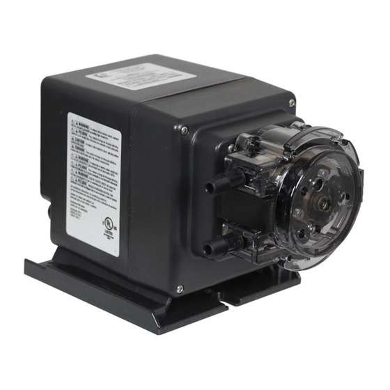
- Page 1 M128 SERIES INSTALLATION AND MAINTENANCE MANUAL PERISTALTIC METERING PUMPS SINCE 1957 WARNING TO BE INSTALLED AND MAINTAINED BY PROPERLY TRAINED PROFESSIONAL INSTALLER ONLY. READ MANUAL & LABELS FOR ALL SAFETY INFORMATION & INSTRUCTIONS.
-
Page 2: Table Of Contents
TABLE OF CONTENTS WARRANTY AND SERVICE POLICY..........3 SAFETY INFORMATION ....cover, 4-6, 9, 11, 14-19, 21-22, 27 OUTPUT AND SIZING ............. 6 MATERIALS OF CONSTRUCTION ..........7 ACCESSORY CHECKLIST ............8 INSTALLATION ..............9-18 TROUBLESHOOTING............19-21 TUBE REPLACEMENT ............22-26 CLEANING THE POINT OF INJECTION ......... - Page 3 WARRANTY AND CUSTOMER SERVICE LIMITED WARRANTY Stenner Pump Company will for a period of one (1) year from the date of purchase (proof of purchase required) repair or replace – at our option – all defective parts. Stenner is not responsible for any removal or installation costs.
-
Page 4: Safety Information
SAFETY INFORMATION IMPORTANT SAFETY INSTRUCTIONS When installing and using this electrical equipment, basic safety precautions should always be followed, including the following: READ AND FOLLOW ALL INSTRUCTIONS Warns about hazards that CAN cause death, serious personal injury, or property damage if ignored. ELECTRIC SHOCK HAZARD ELECTRIC SHOCK HAZARD Pump supplied with grounding power cord and attached plug. - Page 5 SAFETY INFORMATION continued Warns about hazards that WILL or CAN cause minor personal injury or property damage if ignored. PLUMBING Chemical feed pump installation must always adhere to your local plumbing codes and requirements. Be sure installation does not constitute a cross connection. Check local plumbing codes for guidelines.
-
Page 6: Output And Sizing
OUTPUT AND SIZING CHARTS FLOW RATE OUTPUT CHART – 25 psi (1.7 bar) maximum Item Number Ounces Gallons Gallons Milliliters Liters Liters Model Pump Tube per Minute per Hour per Day per Minute per Hour per Day Prefix 249.7 14.9 359.6 Approximate Maximum Output @ 50/60Hz Maximum system water flow for 1:128 dosing is 8.4 gallons/minute or 31.8 liters/minute. -
Page 7: Materials Of Construction
MATERIALS OF CONSTRUCTION All Housings Polycarbonate Pump Tube & Check Valve Duckbill Santoprene , FDA approved ®* Suction/Discharge Tubing & Ferrules Polyethylene, FDA approved Tube and Injection Fittings PVC or Polypropylene, NSF listed Connecting Nuts PVC, NSF listed Suction Line Strainer and Cap PVC or Polypropylene, NSF listed, with ceramic weight Fasteners Stainless Steel... -
Page 8: Accessory Checklist
ACCESSORY CHECKLIST CONTENTS 3 Connecting Nuts 1/4" 3 Ferrules 1/4" 1 Injection Fitting 25 psi (1.7 bar) maximum OR 1 Injection Check Valve 100 psi (6.9 bar) maximum 1 Weighted Suction Line Strainer 1/4" 1 20' Roll of Suction/Discharge Tubing 1/4" White 1 Additional Pump Tube 2 Additional Latches 1 Mounting Bracket... -
Page 9: Installation
INSTALLATION ADDITIONAL SAFETY INSTRUCTIONS NOTICE: Indicates special instructions or general mandatory action. Read all safety hazards before installing or servicing the pump. The pump is designed for installation and service by properly trained personnel. Use all required personal protective equipment when working on or near a chemical metering pump. - Page 10 INSTALLATION – OPERATION AND CONTROLS The M128 Series pump is designed to automatically meter solution proportional to flow at a rate of 1 ounce of solution to 128 ounces of process water. The pump is pre-set at the factory to work with a specific tube size; the tube size can’t be changed. The M05 model is pre-set with a #5 tube and the M07 model is pre-set with a #7 tube.
- Page 11 INSTALLATION continued MOUNT PUMP Pump must be mounted vertically with pump head pointed downward. Select a dry location (to avoid water intrusion and pump damage) above the solution tank. Best recommended location is above the solution tank in a vertical position with the pump head pointed downward and the spill recovery (see page 13) in place to reduce the risk and severity of damage.
- Page 12 INSTALLATION continued SPILL RECOVERY In case of tube rupture, the solution drains back into the tank, preventing spillage onto ground or floor and stops the solution from collecting in the tube housing. Tube drains solution back to tank. Punch out one of two hole plugs using a 7/32"...
- Page 13 INSTALLATION DIAGRAM Plug into Grounded Power Outlet (Ground- Fault Circuit-Interrupter GFCI recommended) Wall Mounting Bracket (requires 2 screws) Disassembled View Injection Injection Check Valve Fitting 100 psi max. 25 psi max. Pump Input Signal Cable Duckbill Suction Line Discharge Line Flow direction of solution Spill Recovery Injection Check Valve...
- Page 14 INSTALLATION continued Risk of equipment malfunction or damage. DO NOT connect input signal cord to any AC electrical supply. NOTICE: Indicates special instructions or general mandatory action. Use the M128 only with a dry contact, reed switch style water meter. DO NOT connect the M128 input signal cord to any AC voltage supply.
- Page 15 INSTALLATION continued INSTALL SUCTION LINE TO PUMP HEAD 1. Uncoil the suction/discharge line. Use outside of solution tank as a guide to cut proper length of suction line ensuring it will be 2-3" above the bottom of solution tank. Allow sufficient slack to avoid kinks and stress cracks. Always make a clean square cut to assure that the suction line is burr free.
- Page 16 INSTALLATION continued INSTALL SUCTION WEIGHT TO SUCTION LINE 1. Drill a hole into the bung cap or solution tank lid. Slide the tubing through and secure the weighted strainer to the line. 2. To attach the strainer, push approximately 3.5" of suction line through the cap on the strainer body.
- Page 17 INSTALLATION continued INSTALL DISCHARGE LINE TO PUMP HEAD AND INJECTION POINT 1. Make a secure finger tight connection on the discharge fitting of the pump head as instructed in Install Suction Line instructions. DO NOT use thread seal tape on pump tube connections or tools to tighten connections.
- Page 18 www.stenner.com...
-
Page 19: Troubleshooting
TROUBLESHOOTING – MOTOR HAZARDOUS VOLTAGE: DISCONNECT power cord before removing motor cover for service. Electrical service should be performed by trained personnel only. PROBLEM POSSIBLE CAUSE SOLUTION Pump does not respond to Failed reed switch on water meter Disconnect signal wire and briefly touch the water meter signal two leads from the pump together. - Page 20 TROUBLESHOOTING – PUMP HEAD PROBLEM POSSIBLE CAUSE SOLUTION Components cracking Chemical attack Check chemical compatibility Pump head leaking Pump tube rupture Replace pump tube, ferrules; center tube No pump output, Depleted solution tank Replenish solution pump head rotates Pump suction line weight is Maintain suction line 2-3"...
- Page 21 TROUBLESHOOTING – PUMP TUBE NOTICE: A leaking pump tube damages the metering pump. Inspect pump frequently for leakage and wear. Refer to Tube Replacement section for additional safety precautions and instructions. PROBLEM POSSIBLE CAUSE SOLUTION Tube leaking Pump tube ruptured Replace pump tube, ferrules;...
- Page 22 TUBE REPLACEMENT – SAFETY INFORMATION RISK OF CHEMICAL EXPOSURE To reduce risk of exposure, check the pump tube regularly for leakage. At the first sign of leakage, replace the pump tube. To reduce risk of exposure, the use of proper personal protective equipment is mandatory when working on or near chemical metering pumps.
-
Page 23: Tube Replacement
TUBE REPLACEMENT continued PREPARATION 1. Follow all safety precautions prior to tube replacement. 2. Prior to service, pump water or a compatible buffer solution through the pump and suction and discharge lines to remove chemical and avoid contact. REMOVE THE PUMP TUBE Open latches 1. - Page 24 TUBE REPLACEMENT continued 6. Hold the pump securely, use the tube housing cover as a wrench and quickly (snap) rotate the cover counter-clockwise to collapse the roller assembly. The tube will no longer be pressed against the tube housing wall. Illustration E NOTE: Counter-clockwise is viewed from facing the head of the pump.
- Page 25 TUBE REPLACEMENT continued INSTALL THE TUBE / EXPAND THE ROLLER ASSEMBLY 1. Ensure the power to the pump is off and the input signal is disconnected. 2. Place the new tube in the pump head, use your fingers to ensure that it centered over the rollers. Illustration H Place new tube 3.
- Page 26 TUBE REPLACEMENT continued CENTER THE TUBE 1. Lift the latch located between the tube fittings, leaving the end of the latch engaged with the lip on the tube housing cover. Leave the latch on the opposite Back of side engaged. Illustration N latch open 2.
-
Page 27: Cleaning The Point Of Injection
CLEANING THE POINT OF INJECTION – SAFETY INFORMATION NOTICE: Indicates special instructions or general mandatory action. NOTICE: Low-pressure models are installed using an injection fitting and high-pressure models use an injection check valve. Both allow the extension tip to be installed in the center of the pipe directly in the flow of water to help reduce deposit accumulation. - Page 28 CLEANING THE POINT OF INJECTION continued 1. Disconnect power by unplugging pump power cord. Disable water pump or auxiliary equipment electrical supply. 2. Depressurize system and bleed pressure from pump discharge line. 3. Loosen and remove connecting nut and ferrule from the injection check valve or injection fitting to disconnect discharge line.
- Page 29 CLEANING THE POINT OF INJECTION continued 5. Replace discharge line if cracked or deteriorated. If the end is clogged, cut off the calcified or blocked section of discharge line. 25 psi Max. Model (includes injection fitting) Replace ferrule and reinstall the discharge line to the injection fitting approximately 3/4"-1"...
-
Page 30: Parts
PARTS Tube Housing with Latches Roller Assembly Tube Housing Cover Pump Tube PUMP HEAD PARTS DESCRIPTION 2-PK 4-PK Tube Housing & Latches QP400-1 QP400-2 ––––––––– QP500–1 ––––––––– QP500–4 Roller Assembly QP100–1 ––––––––– QP100–4 Tube Housing Cover & Bushing PUMP TUBES Includes ferrules 1/4"... - Page 31 PARTS Connecting Nuts 1/4" Ferrules 1/4" Latches Roller Assembly Pump Tube Pump Head Pump Head Service Kit PUMP HEAD 25 psi max. Includes tube, ferrules 1/4" DESCRIPTION 2-PK QP255-1 QP255-2 #5 Santoprene Pump Head ® PUMP HEAD 100 psi max. Includes tube, duckbill, ferrules 1/4"...
- Page 32 STENNER PUMP COMPANY 3174 DeSalvo Road Jacksonville, Florida 32246 USA Phone: 904.641.1666 US Toll Free: 800.683.2378 Fax: 904.642.1012 sales@stenner.com www.stenner.com Hours of Operation (EST): Mon.–Thu. 7:30 am–5:30 pm Fri. 7:00 am–5:30 pm Assembled in the USA © Stenner Pump Company All Rights Reserved IM128 031518...
- Page 33 SERIE M128 MANUAL DE INSTALACION Y MANTENIMIENTO DOSIFICADORES PERISTALTICOS DESDE 1957 ADVERTENCIA INSTALACION DEBE SER REALIZADA Y MANTENIDA POR PROFESIONALES DEBIDAMENTE ENTRENADOS. LEA EL MANUAL Y LAS ETIQUETAS PARA OBTENER LAS INSTRUCCIONES Y LA INFORMACION DE SEGURIDAD.
- Page 34 INDICE GARANTIA Y NORMAS DE SERVICIO......... 3 INFORMACION DE SEGURIDAD..portada, 4-6, 9, 11, 14-19, 21-22, 27 TABLAS DE CAUDALESA............6 MATERIALES DE CONSTRUCCION ..........7 LISTA DE VERIFICACION DE ACCESORIOS......... 8 INSTALACION ..............9-18 GUIA DE REPARACION DE AVERIAS........19-21 CAMBIO DE TUBOS ............
-
Page 35: Garantia Y Normas De Servicio
GARANTIA Y NORMAS DE SERVICIO GARANTIA LIMITADA Stenner Pump Company cambiará o reparará (nuestra opción) todo producto defectuoso por un año desde el momento de compra (se requiere comprobante/recibo de compra). Stenner no es responsable por los costos de cambio y reemplazo de partes. Tubos de bombeo y otras partes de goma son partes de desgaste y no están cubiertos bajo la garantía. - Page 36 INSTRUCCIONES DE SEGURIDAD INSTRUCCIONES DE SEGURIDAD IMPORTANTES Al instalar y usar este equipo eléctrico, siempre se deben seguir las precauciones básicas de seguridad, incluyendo las siguientes: LEA Y SIGA TODAS LAS INSTRUCCIONES Advierte sobre peligros que PUEDEN causar la muerte, lesiones personales graves o daño a la propiedad si se le ignora.
-
Page 37: Informacion De Seguridad
INFORMACION DE SEGURIDAD (continuación) Advierte sobre peligros que PUEDEN causar o que CAUSARÁN lesiones personales menores o daño a la propiedad si se les ignora. TUBERIAS: La instalación del dosificador de químicos siempre debe cumplir con sus códigos y requisitos de tubería locales. Asegúrese de que en la instalación no se realice una conexión cruzada. -
Page 38: Tablas De Caudalesa
TABLAS DE CAUDALES M128 – Tabla de Caudales 25 psi (1.7 bar) máximo Prefijo No. Tubo de Onzas Galones Galones Mililitros Litros Litros Modelo de Parte bombeo por minuto por hora por día por minuto por hora por día 249.7 14.9 359.6 Caudal aproximado a 50/60Hz... -
Page 39: Materiales De Construccion
MATERIALES DE CONSTRUCCION Todas las carcasas Policarbonato Tubo de bombeo y goma de válvula de inyección Santoprene ,Aprobados por FDA ®* Tubos de succión y descarga y casquillos Polietileno, aprobado por FDA Conexiones de tubos y de punto inyección PVC o Polipropileno, listado por la NSF Tuercas de conexión PVC, listado por NSF Filtro de succión con pesa y tapa... - Page 40 LISTA DE VERIFICACION DE ACCESORIOS CONTENIDO 3 Tuercas de Conexión de 1/4" 3 Casquillos de 1/4" 1 Conexión de inyección 25 psi (1.7 bar) máximo o 1 Válvula de Inyección 100 psi (6.9 bar) máximo 1 Filtro de succión con pesa de 1/4" 1 Rollo de 20 pies de tubo de succión y descarga de 1/4"...
-
Page 41: Instalacion
INSTALACION INSTRUCCIONES DE SEGURIDAD ADICIONALES AVISO: Indica instrucciones especiales o acción obligatoria general. Lea todos las advertencias de seguridad antes de instalar o reparar su dosificador. El dosificador ha sido diseñado para ser instalado por personal entrenado debidamente. Utilice todo el equipo de protección personal requerido al trabajar en o cerca de un dosificador de productos químicos. - Page 42 INSTALACION FUNCIONAMIENTO Y CONTROLES El dosificador M128 está diseñado para bombear solución automáticamente, de forma proporcional al flujo; 1 onza por cada 128 onzas de agua de proceso. El dosificador está pre-configurado de fábrica con un tubo de bombeo específico; el tubo no debe ser cambiado.
- Page 43 INSTALACION (continuación) MONTAJE DEL DOSIFICADOR El dosificador se debe montar de forma vertical con el cabezal hacia abajo. Seleccione un lugar seco (para evitar daños por intrusión de agua y daño en el dosificador) sobre el tanque de solución. El lugar más recomendado es arriba del tanque de solución en una posición vertical con el cabezal del dosificador hacia abajo y el sistema de recuperación de pérdidas (vea la página 13) en su lugar para reducir el riesgo y la gravedad de los daños.
- Page 44 INSTALACION (continuación) RECUPERACION DE PERDIDAS En caso de ruptura del tubo, la solución se drena hacia el tanque, evitando que se derrame al suelo y que se deposite en el cabezal. El tubo drena la solución nuevamente hacia el tanque. Perfore uno de los dos agujeros parciales utilizando herramienta perforadora de...
- Page 45 DIAGRAMA DE INSTALACION Receptáculo con conexión a tierra adecuado; protegido por interruptor diferencial (GFCI) Soporte de montaje de pared (requiere 2 tornillos) Disassembled View Cable de señal de Válvula de Conexión de entrada del dosificador inyección inyección 100 psi 25 psi (6.9 bar) (1.7 bar) máximo...
- Page 46 INSTALACION (continuación) Riesgo de desperfecto o daño del equipo. NO conecte el cable de señal de entrada a cualquier fuente eléctrica de corriente alterna. NOTICE: Indica instrucciones especiales o acción obligatoria general. Utilice el M128 sólo con un medidor de agua de contacto seco con interruptor magnético.
- Page 47 INSTALACION (continuación) CONECTE EL TUBO DE SUCCION AL CABEZAL DEL DOSIFICADOR 1. Desenrosque el tubo de succión y descarga. Utilice el exterior del tanque de solución como una guía para cortar la longitud adecuada de tubo de succión, asegurando que quede a 7-8 cm del fondo del tanque.
- Page 48 INSTALACION (continuación) INSTALE EL FILTRO CON PESA AL TUBO DE SUCCION 1. Perfore un orificio en la tapa o cubierta del tanque de solución. Deslice el tubo de succión en el mismo y conecte el filtro con pesa al tubo. 2.
- Page 49 INSTALACION (continuación) CONECTE EL TUBO DE DESCARGA AL CABEZAL DEL DOSIFICADOR Y AL PUNTO DE INYECCION 1. Realice una conexión segura con los dedos en el extremo de descarga del cabezal del dosificador como se indica en las instrucciones de instalación del tubo de succión. NO use cinta aisladora de rosca en las conexiones del tubo de bombeo o herramientas para apretar las conexiones.
- Page 50 INSTALACION (continuación) 4. Enrosque a mano la conexión de inyección a la conexión FNPT. Modelos de 25 psi (1.7 bar) máximo (incluye conexión de inyección) Deslice la tuerca de conexión y casquillo en el tubo de descarga del dosificador. Inserte el tubo de descarga en la conexión de inyección hasta llegar al tope. Apriete a mano la tuerca de conexión.
- Page 51 GUIA DE REPARACION DE AVERIAS – MOTOR VOLTAJE PELIGROSO: DESCONECTE el cable eléctrico antes de sacar la tapa del motor para repararlo. Reparaciones deben ser realizadas por personal entrenado. PROBLEMA POSIBLE CAUSA SOLUCION El dosificador no responde Falló el interruptor magnético en Desconecte el cable de señal y toque a la señal del medidor el medidor de agua...
-
Page 52: Guia De Reparacion De Averias
GUIA DE REPARACION DE AVERIAS – CABEZAL DEL DOSIFICADOR PROBLEMA POSIBLE CAUSA SOLUCION Agrietamiento de Daño químico Verifique la compatibilidad del químico los componentes Pérdida en el cabezal Ruptura del tubo de bombeo Cambie el tubo y los casquillos; centre v del dosificador el tubo No hay caudal,... - Page 53 GUIA DE REPARACION DE AVERIAS – TUBO DE BOMBEO NOTICE: Las pérdidas en el tubo de bombeo dañan el dosificador. Inspeccione el dosificador con frecuencia para detectar pérdidas o desgaste. Consulte la sección de Cambio de tubo para leer precauciones de seguridad e instrucciones adicionales PROBLEMA POSIBLE CAUSA SOLUCION...
-
Page 54: Cambio De Tubos
CAMBIO DE TUBOS – INSTRUCCIONES DE SEGURIDAD RIESGO DE CONTACTO QUIMICO Para reducir el riesgo de exposición a químicos, chequee el tubo de bombeo regularmente por pérdidas. A la primera señal de pérdida, cambie el tubo de bombeo. Para reducir el riesgo de exposición a químicos, es mandatorio el uso de un equipo protectivo apropiado cuando esté... - Page 55 CAMBIO DE TUBOS (continuación) PREPARACION 1. Siga todas las precauciones de seguridad antes de cambiar el tubo. 2. Antes de realizar servicio, dosifique agua o una solución neutral compatible a través del dosificador y el tubo de succión y descarga para eliminar los químicos y evitar contacto.
- Page 56 CAMBIO DE TUBOS (continuación) 6. Sostenga el dosificador con firmeza. Utilice la tapa como llave y gírela rápidamente (con un movimiento corto y veloz) en sentido contrario al reloj, para contraer el conjunto de rodillos. El tubo ya no estará presionado contra la pared de la carcasa.
- Page 57 CAMBIO DE TUBOS (continuación) INSTALE EL TUBO Y EXPANDA EL CONJUNTO DE RODILLOS 1. Asegúrese que el dosificador esté apagado y que la señal de entrada esté desconectada. 2. Coloque el tubo nuevo en el cabezal, utilice sus dedos para centrarlo sobre los rodillos. Instale el tubo nuevo Ilustración H 3.
- Page 58 CAMBIO DE TUBOS (continuación) CENTRE EL TUBO 1. Levante la parte trasera del sujetador que se encuentra entre las conexiones del tubo, dejando el extremo delantero Parte enganchado en la tapa de la carcasa. trasera del sujetador Deje el otro sujetador completamente abierta cerrado.
-
Page 59: Limpieza Del Punto De Inyeccion
LIMPIEZA DEL PUNTO DE INYECCION – INFORMACION DE SEGURIDAD NOTICE: Indica instrucciones especiales o acción obligatoria general. NOTICE: Los modelos de baja presión se instalan usando una conexión de inyección y los modelos de alta presión usan una válvula de inyección. Ambos permiten que la punta del conector de inyección se instale en el centro de la tubería, directamente en el flujo de agua, para ayudar a reducir la acumulación de depósitos. - Page 60 LIMPIEZA DEL PUNTO DE INYECCION (continuación) 1. Apague y desenchufe el dosificador. Inhabilite la bomba de agua u otro equipo auxiliar. 2. Despresurice el sistema y purgue la presión del tubo de descarga del dosificador. 3. Suelte y quite la tuerca de conexión y casquillo de la válvula de inyección o conexión de inyección para desconectar el tubo de descarga.
- Page 61 LIMPIEZA DEL PUNTO DE INYECCION (continuación) 5. Cambie el tubo de descarga si está agrietado o deteriorado. Si el extremo está obstruido, corte la sección calcificada u obstruida del tubo de descarga. Modelos de 25 psi (1.7 bar) máximo (incluye conexión de inyección) Cambie el casquillo y vuelva a instalar el tubo de descarga al conector, introduciendo el mismo hasta encontrar el tope.
-
Page 62: Partes
PARTES Carcasa y Ajustadores Conjunto de rodillos Tapa del cabezal Tubo de bombeo PARTES DEL CABEZAL Descripción Paquete de 2 Paquete de 4 Carcasa y Ajustadores QP400-1 QP400-2 ––––––––– Conjunto de rodillos QP500–1 ––––––––– QP500–4 Cubierta del Cabezal con cojinete QP100–1 –––––––––... - Page 63 PARTES Tuercas de Conexión Férrulas de 1/4 de pulgada Sujetadores Conjunto de rodillos Tubo de bombeo Cabezal Kit de servicio del cabezal CABEZAL 25 psi (1.7 bar) máx. Incluye tubo, férrulas de 1/4 de pulgada Descripción Paquete de 2 QP255-1 QP255-2 Cabezal con tubo de Santoprene ®...
- Page 64 STENNER PUMP COMPANY 3174 DeSalvo Road Jacksonville, Florida 32246 USA Teléfono: +1.904.641.1666 Línea gratuita en EE. UU.: 1.800.683.2378 Fax: +1.904.642.1012 sales@stenner.com www.stenner.com Horario de atención (GMT–05:00. Costa este USA): Lunes a jueves de 7:30 a.m. a 5:30 p.m. Viernes, de 7:00 a.m. a 5:30 p.m. Ensamblado en EE.
Need help?
Do you have a question about the M128 Series and is the answer not in the manual?
Questions and answers