
Related Manuals for NCR 7703-K390


Summary of Contents for NCR 7703-K390
- Page 1 Kit Instructions 2x20 Adjustable High Mount without Display 7703-K390/K490 Issue B...
-
Page 2: Revision Record
NCR, therefore, reserves the right to change specifications without prior notice. All features, functions, and operations described herein may not be marketed by NCR in all parts of the world. In some instances, photographs are of equipment prototypes. Therefore, before using this document, consult with your NCR representative or NCR office for information that is applicable and current. -
Page 3: Kit Contents
• NCR XR5 POS (7701) on an X-Series Stand (7702-K031) or P-Series Stand (7701-K032) • NCR XR7 POS (7702) on an X-Series Stand (7702-K031) or P-Series Stand (7701-K032) • NCR XR7 Plus POS (7703) on an X-Series Stand (7702-K031) - Page 4 2x20 Adjustable High Mount without Display Item Part Number Description 006-8611456 Nut – Keps (4-40) 006-8623674 Screw – M4x0.7Px8mm, Machine, Phillips, Pan Head 006-8625408 4-40 x 1/4 inch Steel with Clear Zinc Plating Fillister Head, Phillips Screw 497-0521275 Assembly, Serial Expansion Housing with Screws, White 006-8622686 Screw, SEMS, M4 X 12, Pan Head, Phillips, Steel 7703-K490 2x20 Adjustable High Mount without Display...
-
Page 5: Installation Procedure
2x20 Adjustable High Mount without Display Installation Procedure 1. Remove the Stand. a. Lay the terminal face down on a flat surface. Caution: Always use a soft material (cloth, foam) to protect the display screen when placing the terminal face down. b. - Page 6 2x20 Adjustable High Mount without Display 2. Remove the existing Serial Expansion Housing. a. Remove the Serial Expansion Module from the Stand (3 screws). b. Remove the four (4) screws securing the Serial Expansion Board to the Serial Expansion Housing. c. Remove the Serial Expansion Board from the Serial Expansion Housing.
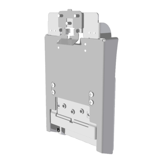
- Page 7 3. Install the new Serial Expansion Housing included in the kit. a. Route the cable through the opening of the new Serial Expansion Housing: • 497-0521275 (included in 7703-K390) • 497-0514376 (included in 7703-K490) b. Mount the Serial Expansion Board on the Serial Expansion Housing. Ensure the Cable Grommet is mounted on the grommet guide of the Serial Expansion Housing.
- Page 8 2x20 Adjustable High Mount without Display d. Install the Serial Expansion Module to the Stand (3 screws). 4. Reinstall the Stand. a. Insert the Serial Expansion Housing Tabs into the openings in the Back Housing and rotate the Stand downward.
- Page 9 2x20 Adjustable High Mount without Display b. Secure the stand to the terminal using two (2) captive screws. 5. Install the Customer Display on the Mounting Bracket Assembly. a. Mount the Cable Strain Relief to the Cable Management Bracket.
- Page 10 2x20 Adjustable High Mount without Display b. Connect the USB Cable to the Customer Display. Note the cable routing (Cable Management Bracket removed for clarity). c. Insert the tab on the edge of the Cable Management Bracket into the slot in the Rear Cover of the Customer Display.
- Page 11 2x20 Adjustable High Mount without Display d. Pivot the Cable Management Bracket until it snaps into position. e. Route the Cable between the Display Mount Swivel Bracket and the High Mount Base Bracket.
- Page 12 2x20 Adjustable High Mount without Display f. Attach the Customer Display on the Display Mount Swivel Bracket using three (3) screws. 6. Install the Customer Display and Mounting Bracket Assembly. a. Route the Cable as shown.
- Page 13 2x20 Adjustable High Mount without Display b. Slide the Customer Display and Mounting Bracket Assembly over the Serial Expansion Housing of the terminal. c. Secure the Assembly to the terminal using four (4) screws. d. Pivot the terminal and open the cable cover.
- Page 14 2x20 Adjustable High Mount without Display e. Connect the USB Cable to any available +12V USB Port on the terminal.
Need help?
Do you have a question about the 7703-K390 and is the answer not in the manual?
Questions and answers