Advertisement
Quick Links
Advertisement

Related Manuals for NCR 7772-K030


Summary of Contents for NCR 7772-K030
- Page 1 Kit Instructions Stand, CX7 7772-K030 Issue B...
-
Page 2: Revision Record
NCR, therefore, reserves the right to change specifications without prior notice. All features, functions, and operations described herein may not be marketed by NCR in all parts of the world. In some instances, photographs are of equipment prototypes. Therefore, before using this document, consult with your NCR representative or NCR office for information that is applicable and current. -
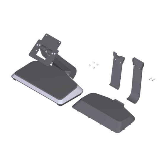
Page 3: Kit Contents
Stand, CX7 This kit provides a Stand for the NCR CX7 All-in-One POS (7772) or NCR CX5 All-in- One POS (7773). Kit Contents... - Page 4 Stand, CX7 Item Part Number Description Stand Assembly 497-0523815 Base, HSG, Cast, Silver 497-0523819 Neck, Center, Cast, Silver 497-0523775 Base, Trim, Bottom, Blk7 497-0523779 Base, Foot, Center, Blk7 497-0524135 Base Feet, CX7, Blk7 497-0528039 Hinge, CX, Blk7 497-0523767 Base, Cover, Top, Remote Power Supply, Blk7 497-0531326 Mounting Plate –...
-
Page 5: Installation Procedure
Stand, CX7 Installation Procedure Installing the Stand Warning: Disconnect the AC power cord from the AC outlet and wait 30 seconds before servicing the terminal. 1. Install the CX7 with Integrated I/O on the Bracket (4 screws). Note: For clarity, the Neck Cover is not shown in the illustration. 2. - Page 6 Stand, CX7 b. Rotate the Door forward and pull out to remove. 3. Connect the Cables to the I/O. 4. Route the Cables down the Neck as shown.
- Page 7 Stand, CX7 5. Reinstall the Neck Door. a. Hook the Neck Door on the Neck Cover. Position the Door so that the door standoffs (one on each side) sit on the hooks on the inside of the neck cover (one on each side).
- Page 8 Stand, CX7 Installing the Integrated Power Supply Warning: Disconnect the AC power cord from the AC outlet and wait 30 seconds before servicing the terminal. 1. Remove the Neck Door. a. Loosen the two (2) thumbscrews on the Neck Door. b.
- Page 9 Stand, CX7 2. Slightly push the front side of the Base Cover, then pivot the cover open. 3. Route the AC Cord up through the opening in the Base.
- Page 10 Stand, CX7 4. Position the Power Supply in the recess on the Base. Note: The Power Supply Cable comes bundled as shown.
- Page 11 Stand, CX7 5. Set the Ferrite Bead in the small recess on the Base and secure the Cable under the Cable Management Hook. 6. Route the Power Supply Cable. a. Route the Power Supply Cable around the Power Supply with the bundled cable in front as shown.
- Page 12 Stand, CX7 c. On the underside of the Base, pull the DC Connector such that the excess cable is under the Base. 7. Connect the AC Cord to the Power Supply. 8. Hook the Base Cover into the Stand, then snap into place.
- Page 13 Stand, CX7 9. Route the Power Supply Cable up along the Neck as shown and insert the DC Connector into the Power In connector on the Integrated I/O. 10. Reinstall the Neck Door. a. Hook the Neck Door on the Neck Cover. Position the Door so that the door standoffs (one on each side) sit on the hooks on the inside of the neck cover (one on each side).
- Page 14 Stand, CX7 b. Tighten the two (2) thumbscrews. Changing the Neck Covers The kit includes an assembled stand with a wide neck cover and door to allow cable management. The neck covers can be changed to the standard front neck cover (497- 0523791) and back neck cover (497-0523787), which are also included in the kit.
- Page 15 Stand, CX7 b. Rotate the Door forward and pull out to remove. 2. Remove the Base Rear Foot (2 screws).
- Page 16 Stand, CX7 3. Remove the Neck Cover. a. Remove the two (2) Hex Standoffs from the Neck. b. Remove the two (2) screws that secure the Neck Cover to the Neck.
- Page 17 Stand, CX7 c. Remove the Neck Cover. 4. Snap the Back Neck Cover onto the neck. The Cover has a simple snap fit connection at the top.
- Page 18 Stand, CX7 5. Install the Base Rear Foot (2 screws). Ensure the Neck Cover is captured under the Base Rear Foot. Note: The Base Rear Foot serves to manage the cables and hold the bottom of the Neck Cover in place. 6.
- Page 19 Stand, CX7 7. Secure the Front Neck Cover to the Neck with two (2) screws. Use the appropriate screws: • flat head screws for Base without Integrated Power Supply • thumbscrews for Base with Integrated Power Supply...
Need help?
Do you have a question about the 7772-K030 and is the answer not in the manual?
Questions and answers