Inovance IS620P Series User Manual
Hide thumbs
Also See for IS620P Series:
- Manual (109 pages) ,
- User manual (184 pages) ,
- Application manual (221 pages)
Table of Contents
Advertisement
Quick Links
Advertisement
Table of Contents
Troubleshooting

Related Manuals for Inovance IS620P Series


Summary of Contents for Inovance IS620P Series
- Page 2 Co., Ltd. The IS620P series is a high-performance AC servo drive for small and medium power applications. The IS620P series ranges from 100 W to 7.5 kW. It supports the Modbus communication protocol with RS232/RS485 communication port, and thus allowing networking of multiple IS620P drives controlled by a host PC.
- Page 3 • Install an appropriate safety device when this product is to be used on machinery which may cause severe accidents or loss due to trips of the product. • Contact Inovance when this product is to be used on special applications such as atomic energy control, aerospace equipment, transport equipment, medical apparatus, safety devices and other equipment that require high cleanliness.
- Page 4 Contents Preface ........................1 Chapter 1 Servo System Selection................6 1.1 Designation Rules of the Servo Motor and Servo Drive ............8 1.2 Servo System Configuration ....................9 1.3 Adapted Cables ........................10 1.4 Regen Resistor Specifications.................... 15 Chapter 2 Mounting Dimensions of Servo System ..........18 2.1 Installation of the Servo Motor ....................
- Page 5 Chapter 7 Function Code Table ................160 Group H00: Servo Motor Parameters ..................161 Group H01: Servo Drive Parameters..................161 Group H02: Basic Control Parameters ................... 162 Group H03: Input Terminal Parameters .................. 165 Group H04: Output Terminal Parameters ................168 Group H05: Position Control Parameters ................
- Page 6 Servo System Selection...
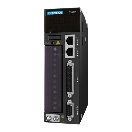
- Page 7 Chapter 1 Servo System Selection IS620P User Manual Chapter 1 Servo System Selection Figure 1-1 Servo drive composition Name Function CN5 analog monitoring Connect to the measuring instrument (such as an oscilloscope ) to signal terminal facilitate viewing signal status when gains are adjusted. LED display Display the running status and parameter setting of the servo system.
- Page 8 IS620P User Manual Chapter 1 Servo System Selection Figure 1-2 Wiring example of three-phase 220 V system Power supply Three-phase 220 Servo drive analog monitoring cable Molded-case circuit breaker (MCCB) Cut off circuit if overcurrent occurs to the protect power supply line. Communication cable for multi-drive parallel connection Noise filter...
- Page 9 Chapter 1 Servo System Selection IS620P User Manual Observe the following precautions during wiring: Note 1: Remove the jumper between terminals and D of the servo drive before connecting a regen resistor. Note 2: CN3 and CN4 are two same communication ports, which can be used at random. Note 3: For the single-phase 220 V servo drive, the main circuit terminals are L1 and L2.
- Page 10 IS620P User Manual Chapter 1 Servo System Selection Figure 1-4 Designation rules of the servo drive IS620 P S 5R5 I - A Mark Customized Specification Mark Series 16-bit high-accuracy analog IS620 Servo drive E-cam, synchronism of gate bridge CANlink Mark Product Type CANopen...
- Page 11 Chapter 1 Servo System Selection IS620P User Manual Servo Drive Model (IS620P□□□□I) Rated Max. Rated Motor Servo Motor Model Drive Drive SN Speed Speed Power Frame Single- Three- (ISMH□-□□□□□□□-*****) Size (H01-02) (RPM) (RPM) Size phase 220 phase 220 40B30CB S2R8 00003 (medium 3000...
- Page 12 IS620P User Manual Chapter 1 Servo System Selection Servo Motor Main Circuit Cable Servo Motor Encoder Cable Servo Connector Kit Motor L = 3.0 m L = 5.0 m L = 10.0 m L = 3.0 m L = 5.0 m L = 10.0 m CN1 terminal CN2 terminal ISMH1...
- Page 13 Chapter 1 Servo System Selection IS620P User Manual Servo Motor Main Circuit Cable Servo Motor Encoder Cable Servo Connector Kit Motor L = 3.0 m L = 5.0 m L = 10.0 m L = 3.0 m L = 5.0 m L = 10.0 m CN1 terminal CN2 terminal ISMH1...
- Page 14 IS620P User Manual Chapter 1 Servo System Selection Table 1-4 Physical appearance of cables for the servo motor and servo drive Cable Cable Name Cable Model Length Cable Appearance (mm) S6-L-M00-3.0 3000 S6-L-M00-5.0 5000 30 mm 100±10 mm S6-L-M00-10.0 10000 L±20 mm 100±5 mm S5-L-M03-3.0...
- Page 15 Chapter 1 Servo System Selection IS620P User Manual Cable Cable Name Cable Model Length Cable Appearance (mm) S6-L-P00-3.0 3000 DB44 plug S6-L-P00-5.0 5000 Note: DB44 is an attached plug, used to connect the CN1 terminal. S6-L-P00-10.0 10000 L±15 mm S60-L-P00-3.0 3000 DB44 plug S60-L-P00-5.0...
- Page 16 Three-phase IS620PT012I 380 V IS620PT017I IS620PT021I IS620PT026I Models IS620PS1R6 and IS620PS2R8 are not configured with a built-in regen resistor. Use an external regen resistor if necessary. For selecting proper external regen resistors, contact Inovance for technical support. - 15 -...
- Page 17 Chapter 1 Servo System Selection IS620P User Manual - 16 -...
- Page 18 Mounting Dimensions...
- Page 19 Chapter 2 Mounting Dimensions of Servo System IS620P User Manual Chapter 2 Mounting Dimensions of Servo System 2.1 Installation of the Servo Motor 2.1.1 Installation Location 1. Install the servo motor in an environment free from corrosive or inflammable gases or combustibles, such as hydrogen sulfide, chlorine, anmonia, sulphur gas, chloridize gas, acid, soda and salt.
- Page 20 IS620P User Manual Chapter 2 Mounting Dimensions of Servo System 2.1.3 Installation Precautions Table 2-2 Installation precautions Item Description Rust-proof Wipe up the antirust agent at the motor shaft end before installing the servo motor, treatment and then take rust-proof treatment. •...
- Page 21 Chapter 2 Mounting Dimensions of Servo System IS620P User Manual Item Description Confirm the IP level of the servo drive in water drop applications (except for the shaft-through portion). In the environment where the shaft-through portion is exposed to oil drops, select and use a servo motor with an oil seal. Observe the following conditions when using the servo motor with oil seal: •...
- Page 22 IS620P User Manual Chapter 2 Mounting Dimensions of Servo System 2.2.2 Installation Environment Table 2-3 Installation environment Item Description 0 to 40°C (The average load rate must not exceed Ambient temperature 80% at 40°C to 55°C.) (no freezing) Environment humidity <...
- Page 23 Chapter 2 Mounting Dimensions of Servo System IS620P User Manual 2. Cooling As shown in the above figure, keep sufficient clearances around the servo drive to ensure cooling by cooling fans or natural convection. Install cooling fans above the servo drive to avoid excessive temperature rise and maintain even temperature inside the control cabinet.
- Page 24 IS620P User Manual Chapter 2 Mounting Dimensions of Servo System Connector Power Side (Including Brake) Encoder Side Plastic housing MOLEX-50361672 AMP 172169-9 Terminal MOLEX-39000059 AMP 1473226-1 Servo Motor Model LL (mm) LG (mm) TP (mm) Weight (kg) ISMH1-10B30CB-U2**Z 106.5 (139.6) M3 x 6 0.59 (0.77) 2) 200 W, 400 W (Vn = 3000 RPM, Vmax = 6000 RPM)
- Page 25 Chapter 2 Mounting Dimensions of Servo System IS620P User Manual 3) 750 W (Vn = 3000 RPM, Vmax = 6000 RPM) 0.06 A 0.02 A 31.5 φ φ 15.5 R8 x 4 -0.1 -0.018 Flat key Shaft end Connector Power Side (Including Brake) Encoder Side Plastic housing MOLEX-50361672...
- Page 26 IS620P User Manual Chapter 2 Mounting Dimensions of Servo System 2.3.2 Overall Dimensions of the ISMH1 Series X Motor 1) 100 W (Vn = 3000 RPM, Vmax = 5000 RPM) 0.04 A 0.02 15.5 φ -0.1 -0.014 φ Flat key Shaft end Connector Power Side...
- Page 27 Chapter 2 Mounting Dimensions of Servo System IS620P User Manual 2) 200 W, 400 W (Vn = 3000 rpm, Vmax = 6000 rpm) 0.06 A 16.5 0.02 A φ φ 5.5 x 4 -0.018 -0.10 R5 x 4 Shaft end Flat key Connector Power Side...
- Page 28 IS620P User Manual Chapter 2 Mounting Dimensions of Servo System 750 W (Vn = 3000 rpm, Vmax = 6000 rpm) 0.06 A 0.02 A φ φ 7 x 4 15.5 -0.018 -0.10 R8 x 4 Shaft end Flat key Connector Power Side Brake Side Encoder Side...
- Page 29 Chapter 2 Mounting Dimensions of Servo System IS620P User Manual 2.3.3 Overall Dimensions of the ISMH2 Series Servo Motor (Vn = 3000rpm, Vmax = 6000/5000 rpm) 1) 1.0 kW, 1.5 kW, 2.0 kW, 2.5 kW 0.06 A 37.5 0.02 A φ...
- Page 30 IS620P User Manual Chapter 2 Mounting Dimensions of Servo System 2) 3.0 kW, 4.0 kW, 5.0 kW 0.10 A 56.5 0.02 A φ -0.2 R15 x 4 φ -0.09 Shaft end Flat key Connector Power Side Brake Side Encoder Side MIL-DTL-5015 series MIL-DTL-5015 series MIL-DTL-5015 series...
- Page 31 Chapter 2 Mounting Dimensions of Servo System IS620P User Manual 2.3.4 Overall Dimensions of the ISMH3 Series Servo Motor (Vn = 1500 RPM, Vmax = 3000 RPM) 1) 850 W, 1.3 kW, 1.8 kW 0.10 A 48.5 0.02 A φ -0.2 -0.09 R15 x 4...
- Page 32 IS620P User Manual Chapter 2 Mounting Dimensions of Servo System 2) 2.9 kW, 4.4 kW, 5.5 kW, 7.5 kW 0.10 A 0.03 A φ φ 13.5 x 4 R30 x 4 -0.20 -0.09 Flat key Shaft end Connector Power Side Brake Side Encoder Side MIL-DTL-5015 series...
- Page 33 Chapter 2 Mounting Dimensions of Servo System IS620P User Manual 2.3.5 Overall Dimensions of the ISMH4 Series Z Servo Motor (Vn = 3000 RPM, Vmax = 6000 RPM) 400 W 0.06 A 16.5 0.02 A 26.5 φ φ 5.5 x 4 11.5 -0.1 R5 x 4...
- Page 34 IS620P User Manual Chapter 2 Mounting Dimensions of Servo System 750 W 0.06 A 0.02 A 31.5 φ φ 7 x 4 15.5 -0.1 -0.018 R8 x 4 Shaft end Flat key Connector Power Side (Including Brake) Encoder Side Plastic housing MOLEX-50361672 AMP 172169-9 Terminal...
- Page 35 Chapter 2 Mounting Dimensions of Servo System IS620P User Manual 2.3.6 Overall Dimensions of the ISMH4 Series Z Servo Motor (Vn = 3000rpm, Vmax = 6000 rpm) 400 W 0.06 A 16.5 0.02 A φ φ 5.5 x 4 -0.018 -0.10 R5 x 4 Flat key...
- Page 36 IS620P User Manual Chapter 2 Mounting Dimensions of Servo System 750 W 0.06 A 0.02 A φ φ 7 x 4 -0.018 15.5 -0.10 R8 x 4 Flat key Shaft end Connector Power Side Brake Side Encoder Side Plastic housing EL-4Y (CWB in Zhejiang) AMP 172165-1 AMP 172169-1...
- Page 37 Chapter 2 Mounting Dimensions of Servo System IS620P User Manual 2.4 Overall Dimensions of the Servo Drive SIZE A: IS620PS1R6I, IS620PS2R8I, IS620PS5R5I SIZE C: IS620PS7R6I, IS620PS012I, IS620PT3R5I, IS620PT5R4I, IS620PT8R4I, IS620PT012I SIZE E: IS620PT017I, IS620PT021I, IS620PT026I Figure 2-2 Overall dimensions of the servo drive Screw hole Servo Screw...
- Page 38 Wiring of Servo System...
- Page 39 Chapter 3 Wiring of Servo System IS620P User Manual Chapter 3 Wiring of Servo System Figure 3-1 Terminal pin arrangement of the servo drive DO4+ +24V DO3- CANH DO3+ CANL GNDG DO2- RS485+ DO2+ PULLHI RS485- PAO+ RS232 DO1- HPULS- RS232 PAO- DO1+...
- Page 40 IS620P User Manual Chapter 3 Wiring of Servo System 3.1 Servo Drive Main Circuit Wiring 3.1.1 Introduction to the Main Circuit Figure 3-2 Servo drive main circuit wiring example Table 3-1 Names and functions of main circuit terminals Terminal Terminal Terminal Function Symbol Name...
- Page 41 Chapter 3 Wiring of Servo System IS620P User Manual Terminal Terminal Terminal Function Symbol Name Common DC For common DC bus connection when multiple servo drives are used bus terminal in parallel. Servo motor U, V, W connection Connect to U, V and W phases of the servo motor. terminals Two grounding terminals are respectively connected to the power Grounding...
- Page 42 SIZE C 0.4–0.6 0.6–1.2 screw M4 combination SIZE E 0.7–1.0 screw Table 3-2 Rated input and output currents of IS620P series servo drive Servo Drive Model Rated Input Current Rated Output Current Max. Output Current (A) (IS620P□□□□I) S1R6 S2R8 10.1 SIZE A 7.9 (single-phase)/3.7...
- Page 43 Chapter 3 Wiring of Servo System IS620P User Manual Table 3-3 Recommended main circuit cable sizes of IS620P series servo drive Servo Drive Model L1C, L2C R, S, T U, V, W (IS620P□□□□I) 18 AWG 16 AWG 16 AWG 16 AWG...
- Page 44 IS620P User Manual Chapter 3 Wiring of Servo System Servo Drive Model L1C, L2C R, S, T U, V, W (IS620P□□□□I) TVR 1.25-3 TVR 1.25-3 TVR 1.25-3 TVR 1.25-3 S7R6 TVR 2-4 TVS 1.25-3 TVS 1.25-3 TVS 1.25-3 TVS 1.25-3 TVR 1.25-3 TVR 2-3M TVR 2-3M...
- Page 45 Chapter 3 Wiring of Servo System IS620P User Manual 3.1.3 Power Supply Wiring Example Figure 3-4 Main circuit wiring of single-phase 220 V servo drive Single-phase 220 VAC IS620P servo drive Noise filter Stop button Main circuit power input button contactors Surge suppressor...
- Page 46 IS620P User Manual Chapter 3 Wiring of Servo System Note 1KM: electromagnetic contactor; 1RY: relay; 1D: bypass diode Connect the main circuit power supply according to the preceding two figures. DOs (ALM+/-) are set as fault output. Power supply is automatically cut off when the servo drive reports an error.
- Page 47 Chapter 3 Wiring of Servo System IS620P User Manual 9. Conduct maintenance after confirming that the CHARGE indicator is OFF. 10. Do not frequently turn ON and OFF the power supply. Do not turn power ON or OFF more than once per minute. Since the servo drive contains a capacitor in the power supply, and high charging current flows for 0.2 seconds when the power supply is turned OFF.
- Page 48 IS620P User Manual Chapter 3 Wiring of Servo System Connector Frame Size of Terminal Pin Layout Appearance Adaptable Motor 4-pin connector Pin No. Signal 40 (X series) 60 (X series) 80 (X series) Recommendation: Plastic housing: EL-4A (CWB); Terminal: 421.6003.0 (CWB) MIL-DTL-5015 series 3108E20-18S aviation plug New Structure...
- Page 49 Chapter 3 Wiring of Servo System IS620P User Manual 3.2 Connecting Servo Motor Encoder Signals Figure 3-7 Example of connecting encoder signals Table 3-8 Connectors of encoder cables on servo drive side Connector Appearance Terminal Pin Layout Pin No. Signal Housing Recommendation: Plastic housing of plug on cable side: DB9P (TELE-DATA...
- Page 50 IS620P User Manual Chapter 3 Wiring of Servo System Frame Size of Connector Appearance Terminal Pin Layout Adaptable Motor MIL-DTL-5015 series 3108E20-29S aviation plug 20-29 aviation plug Pin No. Signal Twisted-pair Shielded Table 3-10 Pin connection relation of encoder cables Motor Side DB9 at Servo Drive Side Function Description...
- Page 51 Chapter 3 Wiring of Servo System IS620P User Manual 5. The shield of the encoder cable must be properly grounded. Differential signals shall be connected to the two wires of the twisted-pair cable. 6. To determine the length of the signal cable, consider voltage drop caused by the cable resistance.
- Page 52 IS620P User Manual Chapter 3 Wiring of Servo System Figure 3-9 Wiring examples in speed/position/torque control mode Standard wiring in speed control mode AI1 20 Low-pass filter Analog speed converter AI2 18 Max. forward Low-pass filter Servo drive analog speed limit GND 19 Standard wiring in position control mode 2.4 kΩ...
- Page 53 Chapter 3 Wiring of Servo System IS620P User Manual 3.3.1 DI/DO Signals Table 3-12 DI/DO signal description Default Signal Pin No. Function Description Function P-OT Forward drive forbidden N-OT Reverse drive forbidden INHIBIT Pulse input forbidden ALM-RST Alarm reset (edge valid) S-ON Servo enabled ZCLAMP...
- Page 54 IS620P User Manual Chapter 3 Wiring of Servo System b) When output signal of the upper device is OC output: Servo drive Servo drive Use 24 V internal Use 24 V external power supply for power supply for NPN input: NPN input: +24V power +24V power...
- Page 55 Chapter 3 Wiring of Servo System IS620P User Manual The following figures are examples of wrong connection. Servo drive Servo drive 5-24 VDC 5-24 VDC No relay connected Relay DO1+ DO1+ Wrong polarity of flywheel diode DO1- DO1- b) When input signal of the upper device is optocoupler input: Servo drive 5-24 VDC Servo drive...
- Page 56 IS620P User Manual Chapter 3 Wiring of Servo System 3.3.3 Position Reference Input Signals Table 3-14 Position reference signal description Signal Pin No. Function Description Common reference pulse PULSE+ Pulse input status: input mode: PULSE- Direction + pulse • Differential drive mode SIGN+ Phase A + B quadrature pulse SIGN-...
- Page 57 Chapter 3 Wiring of Servo System IS620P User Manual Make sure "2.8 V ≤ (H level) - (L level) ≤ 3.7 V". Otherwise, input pulses of the servo drive are unstable, which will cause: When the reference pulse is input, pulse loss occurs. •...
- Page 58 IS620P User Manual Chapter 3 Wiring of Servo System The following two figures show the wiring method when the external 24 V power supply is used. 1) Using internal resistor of the servo drive (recommended) OC pulse position reference: Servo drive Max.
- Page 59 Chapter 3 Wiring of Servo System IS620P User Manual The following figures show the wrong wiring examples: Wrong connection 1: The current-limiting resistor is not connected, resulting in burnout of terminals. Current-limit resistor Servo drive not connected 2.4 kΩ PULLHI 240 Ω...
- Page 60 IS620P User Manual Chapter 3 Wiring of Servo System Wrong connection 4: Terminals are not correctly connected, resulting in burnout of terminals. Servo drive OC signal not 2.4 kΩ connected to PULLHI specified terminal 240 Ω PULSE+ PULSE- 2.4 kΩ 240 Ω...
- Page 61 Chapter 3 Wiring of Servo System IS620P User Manual Make sure the differential input is 5 V. Otherwise, input pulses of the servo drive are unstable, which will cause: When the reference pulse is input, pulse loss occurs. • • When reference direction is input, the direction will reverse.
- Page 62 IS620P User Manual Chapter 3 Wiring of Servo System Encoder phase Z output circuit outputs OC signals. Normally, the encoder phase Z output circuit provides feedback signals to the host controller. The circuit and the host controller together form a closed-loop position control system. An optocoupler circuit, relay circuit, or bus receiver circuit shall be used in the host controller to receive feedback signals.
- Page 63 Chapter 3 Wiring of Servo System IS620P User Manual 1) Wiring example of holding brake The connector of the holding brake is of no polarity. You needs to prepare a 24 V external power supply. The following figure shows the standard wiring of brake signal (/BK) and power supply of the brake.
- Page 64 IS620P User Manual Chapter 3 Wiring of Servo System 3) Servo motor running when servo drive is OFF Servo ON (DI5 input) Servo motor ON BK signal (DO output) H02-12 Position/speed/ torque reference H02-09 H02-11 Motor speed The description of the brake output time sequence is as follows: When the servo is ON, wait for the operation delay time of the brake (as set in H02-09) before sending commands to the servo drive.
- Page 65 Chapter 3 Wiring of Servo System IS620P User Manual The description of brake output time sequence is as follows: When the servo is ON, wait for the operation delay time of the brake (as set in H02-09) before sending commands to the servo drive. Otherwise, the servo drive does not respond. When the servo is OFF, the brake signal is immediately sent out.
- Page 66 IS620P User Manual Chapter 3 Wiring of Servo System Table 3-20 Definition of DB9 terminal pins at PC side Pin No. Description Terminal Pin layout PC-RXD PC receiving end PC-TXD PC sending end Ground CGND Housing PE Shield Figure 3-12 Communication cable appearance Table 3-21 Pin definition of the communication cable RJ45 at Servo Drive Side (A) DB9 at PC Side (B)
- Page 67 Chapter 3 Wiring of Servo System IS620P User Manual Z-TEK, model: ZE551A, 0.8-m USN extension cable, chip model: FT232 Figure 3-14 Appearance of the communication cable for parallel connection of multiple servo drives Table 3-22 Pin definition of the communication cable for parallel connection Signal Pin No.
- Page 68 IS620P User Manual Chapter 3 Wiring of Servo System 3.5 Analog Monitoring Signal Wiring The following figures shows pin layout of the analog monitoring signal terminal CN5. Figure 3-16 Analog monitoring signal terminal Signal Corresponding interface circuit: • Analog output: -10 to +10 V •...
- Page 69 Chapter 3 Wiring of Servo System IS620P User Manual 3.6 Anti-interference Measures for Electrical Wiring Take the following measures to suppress interference: 1. Use cables (such as reference input and encoder cables) as short as possible. 2. Use cables as thick as possible (> 2.0 mm ) for grounding.
- Page 70 IS620P User Manual Chapter 3 Wiring of Servo System 1) Anti-interference wiring example Figure 3-17 Anti-interference wiring example Servo drive filter > 3.5 mm > 3.5 mm > 2.0 mm Grounding plate Grounding Note For the grounding cable connected to the casing, use a cable of at least 3.5 mm thick.
- Page 71 Chapter 3 Wiring of Servo System IS620P User Manual 3.6.2 Using EMI Filters To prevent interference from power cables and reduce impact of the servo drive to other sensitive devices, install an EMI filter on the input side of the power supply according to the input current.
- Page 72 IS620P User Manual Chapter 3 Wiring of Servo System 3) Use a separate grounding cable as short and thick as possible for the EMI filter. Do not share the same grounding cable with other grounding devices. Figure 3-20 Grounding to one point power power filter...
- Page 73 Chapter 3 Wiring of Servo System IS620P User Manual 3.7 Precautions of Using Cables 1. Do not bend or apply tensions to cables. The core wire of a signal cable is only 0.2 or 0.3 mm thin. Handle the cables carefully. 2.
- Page 74 Running and Commissioning...
- Page 75 Chapter 4 Running and Commissioning IS620P User Manual Chapter 4 Running and Commissioning Based on the command modes and running characteristics, the servo drive supports three running modes, position control, speed control, and torque control. In the position control mode, the displacement is determined based on the number of pulses and the speed is determined based on the input pulse frequency.
- Page 76 IS620P User Manual Chapter 4 Running and Commissioning 4.1 Use of the Position Control Mode Figure 4-1 Diagram of the position control mode Servo drive H05-07 Electronic gear ratio 1 (numerator) H05-09 Electronic gear ratio 1 H05-00 Position (denominator) reference source H05-11 Electronic gear ratio 2 H05-04 First-order low- (numerator)
- Page 77 Chapter 4 Running and Commissioning IS620P User Manual 4.1.1 Wiring of the Position Control Mode Figure 4-2 Wiring of the position control mode Servo drive AI1 20 Torque limit: 0-10 V Low-pass filter Impedance: about 9 kΩ Bi-directional Analog output: -10 to 10 V 1 mA meter Maximum output: <...
- Page 78 IS620P User Manual Chapter 4 Running and Commissioning indicates the twisted pair. Note • The signal cables and power cables must be laid separately with the distance at least above 30 • When the signal cable is not long enough and an extension cable needs to be connected, ensure that the shield is connected reliably and the shielding and grounding are reliable.
- Page 79 Chapter 4 Running and Commissioning IS620P User Manual Reference pulse form Select the reference pulse form by setting H05-15. Function Parameter Effective Control Setting Range Unit Default Property Code Name Time Mode 0: Direction + pulse, positive logic 1: Direction + Pulse, negative Reference logic Power-on...
- Page 80 IS620P User Manual Chapter 4 Running and Commissioning Function Effective Control Parameter Name Setting Range Unit Default Property Code Time Mode Electronic gear ratio During H05 07 1–1073741824 1048576 Immediate 1 (numerator) running Electronic gear 1 During H05 09 1–1073741824 10000 Immediate (denominator)
- Page 81 Chapter 4 Running and Commissioning IS620P User Manual 3. Position reference filter The input position references are filtered to make rotation of the servo motor smoother. This function has obvious effects in the following scenarios: • Acceleration/deceleration processing is not performed on the reference pulses output by the host controller and the acceleration/deceleration rate is large.
- Page 82 IS620P User Manual Chapter 4 Running and Commissioning Table 4-2 Different filter effects of two position reference types under the average filter Rectangular Position Reference Ladder Position Reference Average filter time Before filter Position Before filter Position Before filter reference 05-06 After filter reference...
- Page 83 Chapter 4 Running and Commissioning IS620P User Manual Function Setting Control Parameter Name Unit Default Effective Time Property Code Range Mode Encoder frequency- H05 17 35–32767 P/Rev 2500 Power-on again At stop division pulses Table 4-3 Output phase pattern Forward Rotation Reverse Rotation (Phase A Advancing Phase B by 90°) (Phase B Advancing Phase A by 90°)
- Page 84 IS620P User Manual Chapter 4 Running and Commissioning 4.2 Use of the Speed Control Mode Figure 4-5 Diagram of the speed control mode Servo drive H06-00 Main speed H06-05 Acceleration ramp reference A source time constant of speed H06-01 Auxiliary speed reference H06-07 Maximum speed threshold reference B source...
- Page 85 Chapter 4 Running and Commissioning IS620P User Manual 4.2.1 Wiring of the Speed Control Mode Figure 4-6 Wiring of the speed control mode Servo drive Bi-directional Analog output: -10 to 10 V Maximum output: < 1 mA 1 mA meter Bi-directional Analog output: -10 to 10 V 1 mA meter...
- Page 86 IS620P User Manual Chapter 4 Running and Commissioning Note • The signal cables and power cables must be laid separately with the distance at least above 30 • When the signal cable is not long enough and an extension cable needs to be connected, ensure that the shield is connected reliably and the shielding and grounding are reliable.
- Page 87 Chapter 4 Running and Commissioning IS620P User Manual The following table takes AI2 as an example to describe the analog setting of the speed reference. Table 4-4 Analog setting of speed reference Step Operation Remarks Set H06-00 (Main speed reference A source) to Set the speed reference source in the 2 (AI2), and H06-02 (Keypad setting value of speed control mode.
- Page 88 IS620P User Manual Chapter 4 Running and Commissioning View the set speed reference value in H0B-01. The multi-speed references refer to the 16 groups of speed references and related control parameters stored in the internal register and specified internally or via external DI. The multi- speed references can be used in all the three working modes.
- Page 89 Chapter 4 Running and Commissioning IS620P User Manual 2. Reference ramp parameter setting The ramp control function is to change the speed references with large difference to smoother speed references with constant acceleration and deceleration, that is, controlling acceleration and deceleration by setting the acceleration and deceleration time. If the set speed references change greatly, the motor may jitter or vibrate greatly.
- Page 90 IS620P User Manual Chapter 4 Running and Commissioning 3. Speed reference limit The speed references in the speed control mode can be limited. • H06-07 specifies the limit of speed references. The forward or reverse speed references must not exceed the limit. If speed references exceed the limit value, the servo drive outputs the limit value.
- Page 91 Chapter 4 Running and Commissioning IS620P User Manual The related function codes are set in the following table. Function Effective Control Parameter Name Setting Range Unit Default Property Code Time Mode Maximum speed During H06 07 0–6000 6000 Immediate threshold running Forward speed During...
- Page 92 IS620P User Manual Chapter 4 Running and Commissioning 4.3 Use of the Torque Control Mode Figure 4-12 Diagram of the torque control mode Servo drive H07-07 Torque limit source H07-00 Main torque H07-08 T-LMT selection reference A source H07-09 Internal forward torque limit H07-01 Auxiliary torque H07-10 Internal reverse torque limit reference B source...
- Page 93 Chapter 4 Running and Commissioning IS620P User Manual 4.3.1 Wiring of the Torque Control Mode Figure 4-13 Wiring of the torque control mode Servo drive Bi-directional Analog output: -10 to 10 V 1 mA meter Maximum output: < 1 mA Analog output: -10 to 10 V Bi-directional Maximum output: <...
- Page 94 IS620P User Manual Chapter 4 Running and Commissioning Note • The signal cables and power cables must be laid separately with the distance at least above 30 • When the signal cable is not long enough and an extension cable needs to be connected, ensure that the shield is connected reliably and the shielding and grounding are reliable.
- Page 95 Chapter 4 Running and Commissioning IS620P User Manual Torque reference selection In the torque control mode, five methods of obtaining torque references are available, and you can select one in H07-02. Function Parameter Effective Control Setting Range Unit Default Property Code Name Time...
- Page 96 IS620P User Manual Chapter 4 Running and Commissioning When there is interference on the AI1 input signal, set the AI1 input filter time (H03-51). Figure 4-14 No-offset AI1 Torque Torque corresponding to +10 V (+H03-81) T_Ref -10 V Dead zone +10 V Voltage (H03-53)
- Page 97 Chapter 4 Running and Commissioning IS620P User Manual Table 4-6 Speed limit diagram Without Speed Limit With Speed Limit Speed Speed Overspeed may cause mechanical damage. Maximum speed The speed is limited. Speed limit When the speed is limited, the DO terminal outputs the signal described in the following table. Function Function No.
- Page 98 IS620P User Manual Chapter 4 Running and Commissioning Function Parameter Effective Control Setting Range Unit Default Property Code Name Time Mode Reverse speed limit/Speed During H07 20 0–6000 3000 Immediate limit 2 in torque running control 3. Torque reference limit The output torque needs to be limited to protect the mechanism.
- Page 99 Chapter 4 Running and Commissioning IS620P User Manual Function Function No. Description Setting Remarks Name Confirming torque limit FunOUT.7 C-LT Torque limit Valid: Motor torque limited Invalid: Motor torque not limited Allocate the functions and logics to DIs and DOs by setting the related function codes. For example, when setting AI, specify T_LMT in H07-08, and then set the corresponding relationship between the torque and the analog voltage.
- Page 100 IS620P User Manual Chapter 4 Running and Commissioning 4.4 Check Before Running Disconnect the servo motor from the load, the coupling connected to the motor shaft, and other related components. To prevent potential risks, check that the servo motor can work properly without load, and then connect the load.
- Page 101 Chapter 4 Running and Commissioning IS620P User Manual 4.5 Load Inertia Auto-tuning and Gain Adjustment After completing the installation, wiring, and parameter setting correctly, commission the inertia auto-tuning, rigid table, and vibration suppression. Perform inertia auto-tuning (see section 4.5.1) to obtain the correct load inertia ratio. Then, perform automatic gain adjustment (see section 4.5.2).
- Page 102 The inertia auto-tuning may not be maximum speed for inertia auto- supported. Manually set the inertia tuning (H09-06) be increased ratio or contact Inovance. onsite? Hold down the SET key until the keypad displays "SAVE", and then the obtained inertia ratio is written to H08-15.
- Page 103 Chapter 4 Running and Commissioning IS620P User Manual The related function code is set in the following table. Function Effective Control Parameter Name Setting Range Unit Default Property Code Time Mode 0: Positive and Offline inertia negative triangular H09 05 Immediate At stop auto-tuning mode wave mode...
- Page 104 IS620P User Manual Chapter 4 Running and Commissioning Function Parameter Effective Control Setting Range Unit Default Property Code Name Time Mode 0: Disabled, manual adjusting 1: Standard mode, gain parameters automatically Auto- adjusted based on rigidity During H09 00 adjusting table Immediate running...
- Page 105 Chapter 4 Running and Commissioning IS620P User Manual 4.5.4 Notch The mechanical system has a certain resonance frequency. If the gain is too high, resonance around the resonance frequency may occur, and a notch can be used to solve the problem. The notch reduces the gain of the specified frequency to suppress the mechanical resonance.
- Page 106 IS620P User Manual Chapter 4 Running and Commissioning The related function code is set in the following table. Function Parameter Effective Control Setting Range Unit Default Property Code Name Time Mode 0–4 0: Self-adaptive notch not updated 1: Only one notch (3rd notch) valid Working mode 2: Both notches (3rd...
- Page 107 Chapter 4 Running and Commissioning IS620P User Manual - 106 -...
- Page 108 Background Software...
- Page 109 IS620P User Manual Chapter 5 Background Software The background software IS-Opera is provided at www.inovance.cn for free download and use. Install a communication cable (S6-L-T00-3.0), and then the PC can communicate with the servo drive. You can also make the communication cable yourself, and connect the cable according to the instructions in chapter 3.
- Page 110 Troubleshooting...
- Page 111 Chapter 6 Troubleshooting IS620P User Manual Chapter 6 Troubleshooting 6.1 During Startup 6.1.1 Position Control During Fault Cause Confirming Method Startup Phenomenon • After disconnecting CN1, CN2, CN3 and CN4, 1. The control the fault persists. power voltage is abnormal. •...
- Page 112 IS620P User Manual Chapter 6 Troubleshooting During Fault Cause Confirming Method Startup Phenomenon • The high/low-speed pulse input terminal is wired incorrectly. When H05-00 = 0 (pulse reference is the main position reference source), check whether the high/low-speed pulse input terminal is wired correctly by referring to Chapter 3 Wiring of Servo System.
- Page 113 Chapter 6 Troubleshooting IS620P User Manual During Fault Cause Confirming Method Startup Phenomenon • When H05-00 = 0 (pulse reference is the main position reference source), check whether the setting of H05-15 (reference pulse form) is consistent with the actual pulse input. If not, it indicates that H05-15 is set incorrectly or the terminal is wired incorrectly.
- Page 114 IS620P User Manual Chapter 6 Troubleshooting The procedure of removing the cause of positioning inaccurate is as follows: The following figure shows the positioning control schematic diagram. Figure 6-1 Positioning control schematic diagram Servo drive Position reference output device Machine Input reference Count value of output position references...
- Page 115 Chapter 6 Troubleshooting IS620P User Manual If inaccurate positioning occurs, perform as follows: Pout ≠ Pin To remove the cause A, do as follows: Check whether the pulse input terminal (low-speed or high-speed pulse input terminal) is connected with shielded twisted pair (STP) cable. If the open-collector input mode is selected for the low-speed pulse input terminal, change into differential input mode.
- Page 116 IS620P User Manual Chapter 6 Troubleshooting 6.1.2 Speed Control During Fault Cause Confirming Method Startup Phenomenon • After disconnecting CN1, CN2, CN3 and CN4, 1. The control the fault remains. power voltage is • Measure the AC voltage between L1C and abnormal.
- Page 117 Chapter 6 Troubleshooting IS620P User Manual During Fault Cause Confirming Method Startup Phenomenon • The AI wiring is incorrect. When the speed reference is input through AI, check whether the AI input channel is selected correctly and check whether the AI is wired correctly by referring to Chapter 3 Wiring of Servo System.
- Page 118 IS620P User Manual Chapter 6 Troubleshooting During Fault Cause Confirming Method Startup Phenomenon • When AI is selected to input the speed reference, check whether the polarity of input signal is reversed. • When digital setting is used to set the speed reference, check whether H06-03 (keypad setting value of speed reference) is smaller than 0.
- Page 119 Chapter 6 Troubleshooting IS620P User Manual 6.1.3 Torque Control Fault During Startup Cause Confirming Method Phenomenon • After disconnecting CN1, CN2, CN3 and CN4, 1. The control the fault remains. power voltage is abnormal. • Measure the AC voltage between L1C and L2C. The LED display is not 2.
- Page 120 IS620P User Manual Chapter 6 Troubleshooting • The AI wiring is incorrect. When the torque reference is input through AI, check whether the AI is wired correctly by referring to Chapter 3 Wiring of Servo System. • The torque reference selection is incorrect. Check whether H07-02 (torque reference source) is set correctly.
- Page 121 Chapter 6 Troubleshooting IS620P User Manual 6.2 During Running 6.2.1 Fault and Alarm Code List Fault and Alarm Grading ■ The faults and alarms are graded into the following four levels based on the degree of severity: • No.1 non-resettable fault •...
- Page 122 When you view fault/alarm code in H0B-34, the operation panel displays "Er.xxx", where "xxx" is the fault/alarm code. When you read H0B-34 through the servo debugging platform of Inovance or communication, the decimal data must be converted to hexadecimal data. The following table gives examples of data conversion. Er.xxx...
- Page 123 Chapter 6 Troubleshooting IS620P User Manual No.1 non-resettable fault DO Outputs Display Fault Name Fault Type Resettable Groups H02 and above Er.101 NO.1 parameters abnormal Programmable logic Er.102 NO.1 configuration fault Programmable logic Er.104 NO.1 interruption fault Er.105 Internal program abnormal NO.1 Er.108 Parameter storage fault...
- Page 124 IS620P User Manual Chapter 6 Troubleshooting No.1 resettable fault DO Outputs Display Fault Name Fault Type Resettable Different DIs allocated with the Er.130 NO.1 same function Number of DO functions Er.131 NO.1 exceeding the limit Er.207 Shaft D/Q current overflow NO.1 Er.400 Main circuit overvoltage...
- Page 125 Chapter 6 Troubleshooting IS620P User Manual No.2 resettable alarm DO Outputs Display Alarm Name Fault Type Resettable Setting error of frequency- Er.110 NO.3 division pulse output Er.601 Home return timeout NO.3 Er.831 AI zero drift too large NO.3 Er.900 DI emergency braking NO.3 Er.909 Motor overload...
- Page 126 IS620P User Manual Chapter 6 Troubleshooting 6.2.2 Troubleshooting 1. Er.101: Groups H02 and above parameters abnormal Cause: • Total number of function codes changes, which generally occurs after software update. • The actual values of groups H02 and above parameters exceed the limit, which generally occurs after software update.
- Page 127 FPGA software version (H1-01) Contact Inovance for through the operating panel or the drive 1. The FPGA and MCU technical support. Update debugging platform of Inovance. Check versions do not match. matching FPGA or MCU whether the non-zero numbers of the software.
- Page 128 The motor SN does not exist. equipment you are using is the If you use the IS620P series IS620P series servo drive and 20- servo drive and 20-bit servo bit servo motor (-U2***) of Inovance.
- Page 129 Chapter 6 Troubleshooting IS620P User Manual 7. Er.121: Invalid servo ON command Cause: • When some auxiliary functions are used, the redundant servo enabled signal is given. Cause Confirming Method Corrective Action • Check whether auxiliary functions 1. When the servo drive (H0D-02, H0D-03, H0D-12) are Set the external DI and virtual DI is internally enabled, the...
- Page 130 IS620P series servo drive and not match. IS620P series servo drive and 20-bit 20-bit servo motor of Inovance, servo motor (-U2***) of Inovance. ensure that H00-00 = 14000. • Check whether the cable you use is •...
- Page 131 Chapter 6 Troubleshooting IS620P User Manual 12. Er.201: Overcurrent 2 Cause: • The servo drive detects overcurrent on hardware. Cause Confirming Method Corrective Action • Normally, after the operation panel displays "Rdy", set the 1. The reference is input servo enabled signal (S-ON) to and the servo drive is •...
- Page 132 Inovance. • Check whether the cable you use is standard configuration of Inovance and whether the cable is aging, corrosive or is 8. The encoder cable connected loosely. is incorrectly wired,...
- Page 133 Replace the servo drive. again several times, the servo drive is faulty. 2. The communication of • Contact Inovance for technical Contact Inovance for technical the encoder times out. support. support. 15. Er.210: Output-to-ground short-circuit Cause: •...
- Page 134 If you • Check that the equipments you are use the IS620P series servo 3. The encoder type is using are the IS620P series servo drive and 20-bit servo motor set incorrectly or the drive and 20-bit servo motor (-U2***) of (-U2***) of Inovance, ensure wiring is incorrect.
- Page 135 Chapter 6 Troubleshooting IS620P User Manual 18. Er.400: Main circuit overvoltage Cause: The DC bus voltage between P exceeds the overvoltage level. • 220 V drive: normal value: 310 V, overvoltage level: 420 V • 380 V drive: normal level: 540 V, overvoltage level: 760 V Cause Confirming Method Corrective Action...
- Page 136 220 V drive: H0B-26 > 420 V 6. The bus voltage sampling value has a Contact Inovance for technical 380V drive: H0B-26 > 760 V large deviation from the support Measure the DC bus voltage...
- Page 137 Chapter 6 Troubleshooting IS620P User Manual 19. Er.410: Main circuit undervoltage Cause: The DC bus voltage between P is below the undervoltage level. • 220 V drive: normal value: 310 V, overvoltage level: 200 V • 380 V drive: normal level: 540 V, overvoltage level: 380 V Cause Confirming Method Corrective Action...
- Page 138 IS620P User Manual Chapter 6 Troubleshooting 20. Er.420: Power cable phase loss Cause: • One phase or two phases get lost on the three-phase servo drive. Cause Confirming Method Corrective Action • Check whether the RST cables Replace the cables and 1.
- Page 139 Chapter 6 Troubleshooting IS620P User Manual 21. Er.430: Control power undervoltage Cause: • 220 V drive: normal value: 310 V, overvoltage level: 200 V • 380 V drive: normal level: 540 V, overvoltage level: 380 V Cause Confirming Method Corrective Action •...
- Page 140 4. Inovance. 5.The servo drive is • The fault remains after the servo drive Replace the servo drive. faulty. is re-powered on.
- Page 141 Chapter 6 Troubleshooting IS620P User Manual 23. Er.510: Pulse output overspeed Cause: • When the pulse output function is used (H05-38 = 0 or 1), the output pulse frequency exceeds the frequency upper limit allowed by the hardware (2 MHz). Cause Confirming Method Corrective Action...
- Page 142 4. high rigidity. View the servo drive • For IS620P series products, view the bus nameplate and set the motor model in H00-05 and the servo 5. The servo drive or servo drive model (H01- drive model in H01-02.
- Page 143 Confirming Method Corrective Action • Check the running reference and the actual motor speed (H0B-00) by using the drive debugging platform of Inovance or the operation panel. Running reference in the position control 6. Locked-rotor occurs mode: H0B-13 (input reference pulse...
- Page 144 IS620P User Manual Chapter 6 Troubleshooting 28. Er.650: Heatsink overheat Cause: • The power module of the servo drive is higher than the overtemperature protection level. Cause Confirming Method Corrective Action Improve the cooling conditions 1. The ambient • Measure the ambient temperature. to reduce the ambient temperature is too high.
- Page 145 Possible Solution • Check the on-site wiring condition: Check whether there is large-sized • Prefer to use the cable equipment generating interference configured by Inovance as around the servo system or whether standard. there are several variable-frequency • If non-standard cable power devices inside the cabinet.
- Page 146 IS620P User Manual Chapter 6 Troubleshooting 30. Er.834: AD sampling overvoltage Cause: • The AI sampling value is greater than 11.5 V. Cause Confirming Method Corrective Action Measure the voltage input through AI Adjust the AI input voltage and 1. The AI voltage is too and check whether the AI sampling view the AI sampling voltage high.
- Page 147 Confirming Method Corrective Action • Check that the equipments you are 1. The servo drive and using are the IS620P series servo Replace the unmatched servo the servo motor are not drive and 20-bit servo motor (-U2***) drive or motor.
- Page 148 • Monitor the running curve on the drive If the position reference is not debugging platform of Inovance: 5. The servo drive/motor 0, but the position feedback is faulty. is always 0, replace the servo Position reference, position feedback, drive/motor.
- Page 149 Only differential input can be selected of the drive debugging on the condition of using high-speed platform of Inovance. pulse input terminal (H05-01 = 1), the • Then check the grounding ground of the host computer must be...
- Page 150 IS620P User Manual Chapter 6 Troubleshooting Cause Confirming Method Corrective Action • If H05-02 = 0, check the ratios of H05- The ratios of encoder 07/H05-09 and H05-11/H05-13 1.The electronic gear resolution /H05-02, ratio setting exceeds the H05-07/H05-09, and H05-11/ •...
- Page 151 Chapter 6 Troubleshooting IS620P User Manual 6.2.3 Troubleshooting of Alarms 1. Er.110: Setting error of frequency-division pulse output Cause: • When using the frequency-division output function of the encoder (H05-38 = 0), the set number of frequency-division pulses of the encoder does not conform to the threshold decided by the encoder specification.
- Page 152 IS620P User Manual Chapter 6 Troubleshooting 2. Er.601: Home return timeout Cause: • When using the home return function (H05-30 = 1 to 5), the home is not found within the time set in H05-35. Cause Confirming Method Corrective Action If the hardware DI is used, check whether the DI function FunIN.31: HomeSwitch (Home switch) has been...
- Page 153 • Check wirings between the Prefer to use the cable configured 1. Wiring of the motor servo drive, servo motor and by Inovance as standard. and encoder is incorrect encoder according to correct When the self-made cable is or poor.
- Page 154 Adjust the gain by referring to vibrates and generates noise causing too high rigidity. chapter 4. during running. • For IS620P series products, view the bus motor model in View the servo drive nameplate and H00-05 and the servo drive 5. The servo drive or set the servo drive model (H01-02) model in H01-02.
- Page 155 Chapter 6 Troubleshooting IS620P User Manual 6. Er.920: Regen resistor overload Cause: • The accumulative heat of regen resistor is greater than the setting value. Cause Confirming Method Corrective Action Replace with a new external regen • Disconnect the external regen resistor and measure its resistance.
- Page 156 IS620P User Manual Chapter 6 Troubleshooting Cause Confirming Method Corrective Action • Perform the inertia auto-tuning based on section 4.5.1 Inertia Auto-tuning and calculate the total inertia of the machine 7. The load inertia is too according to the mechanical large.
- Page 157 Chapter 6 Troubleshooting IS620P User Manual 8. Er.939: Motor power cable breaking Cause: • The actual phase current of the motor is smaller than 10% of the rated motor current, the actual motor speed is small but the internal torque reference is very large. Cause Confirming Method Corrective Action...
- Page 158 IS620P User Manual Chapter 6 Troubleshooting 11. Er.950: Forward overtravel Cause: • The logic of the DI allocated with function FunIN.14: P-OT (forward drive forbidden) is effective. Cause Confirming Method Corrective Action • Check whether a parameter in group H03 has been allocated The logic of the DI Check the running mode.
- Page 159 H0C-00 is not repeated. 6.2.4 Internal Faults When the following faults occur, contact Inovance for technical support. • Er.104: programmable logic interrupted • Er.111: H00/H01 groups parameters abnormal •...
- Page 160 Function Code Table...
- Page 161 Chapter 7 Function Code Table IS620P User Manual Chapter 7 Function Code Table Function Code Group Parameters Group H00 Servo motor parameters Group H01 Servo drive parameters Group H02 Basic control parameters Group H03 Input terminal parameters Group H04 Output terminal parameters Group H05 Position control parameters Group H06...
- Page 162 IS620P User Manual Chapter 7 Function Code Table Group H00: Servo Motor Parameters Function Effective Parameter Name Setting Range Unit Default Property Code Time 0–65534 Power-on H00 00 Motor SN 65535: motor SN At stop again null Customized H00 02 At display motor SN H00 04 Encoder version...
- Page 163 Chapter 7 Function Code Table IS620P User Manual Group H02: Basic Control Parameters Function Effective Control Parameter Name Setting Range Unit Default Property Code Time Mode 0: Speed mode 1: Position mode 2: Torque mode 3: Torque mode ↔ Speed mode 4: Speed mode ↔...
- Page 164 IS620P User Manual Chapter 7 Function Code Table Function Effective Control Parameter Name Setting Range Unit Default Property Code Time Mode 0: Determined by H02-08 1: Stop at zero speed, keeping Stop mode at H02 07 position locking Immediate At stop overtravel state 2: Stop at zero...
- Page 165 Chapter 7 Function Code Table IS620P User Manual Function Effective Control Parameter Name Setting Range Unit Default Property Code Time Mode Resistor heat H02 24 dissipation 10–100 Immediate At stop coefficient 0: Built-in 1: External, natural cooling Regen resistor 2: External, forced H02 25 Immediate At stop type...
- Page 166 IS620P User Manual Chapter 7 Function Code Table Group H03: Input Terminal Parameters Function Parameter Effective Control Setting Range Unit Default Property Code Name Time Mode Function 0–0xFFFF allocation 1 of Bit0: FunIN.1 Power-on During H03 00 DIs that are Bit1: FunIN.2 again running...
- Page 167 Chapter 7 Function Code Table IS620P User Manual Function Parameter Effective Control Setting Range Unit Default Property Code Name Time Mode Input polarity: 0–4 0: Low level active 1: High level active DI4 logic During H03 09 2: Rising edge active Upon stop selection running...
- Page 168 IS620P User Manual Chapter 7 Function Code Table Function Parameter Effective Control Setting Range Unit Default Property Code Name Time Mode Input polarity: 0–4 0: Low level active 1: High level active DI9 logic During H03 19 2: Rising edge active Upon stop selection running...
- Page 169 Chapter 7 Function Code Table IS620P User Manual Group H04: Output Terminal Parameters Function Parameter Effective Control Setting Range Unit Default Property Code Name Time Mode During H04 00 function 0–19 Upon stop running selection Output polarity reverse setting: 0–1 DO1 logic 0: Output low level when During...
- Page 170 IS620P User Manual Chapter 7 Function Code Table Function Parameter Effective Control Setting Range Unit Default Property Code Name Time Mode 00: Motor rotational speed (1 V/1000 RPM, by default) 01: Speed reference (1 V/1000 RPM) 02: Torque reference (1 V/100%) 03: Position deviation (0.05 V/1 reference unit)
- Page 171 Chapter 7 Function Code Table IS620P User Manual Group H05: Position Control Parameters Function Parameter Effective Control Setting Range Unit Default Property Code Name Time Mode 0: Pulse setting Position 1: Step setting H05 00 reference Immediate At stop 2: Multi-position source setting Pulse...
- Page 172 IS620P User Manual Chapter 7 Function Code Table Function Parameter Effective Control Setting Range Unit Default Property Code Name Time Mode 0: Clear position deviation pulses upon servo drive disabled or fault 1: Clear position H05 16 Clear action deviation pulses Immediate At stop upon fault 2: Clear position...
- Page 173 Chapter 7 Function Code Table IS620P User Manual Function Parameter Effective Control Setting Range Unit Default Property Code Name Time Mode Interruption 1: Enabled Power-on H05 23 At stop fixed length 0: Disabled again Displacement 10000 During H05 24 of interruption 0–1073741824 reference reference...
- Page 174 IS620P User Manual Chapter 7 Function Code Table Function Parameter Effective Control Setting Range Unit Default Property Code Name Time Mode 0: Forward home return, deceleration position and home as home switches 1: Reverse home return, deceleration position and home as home switches 2: Forward home return, deceleration...
- Page 175 Chapter 7 Function Code Table IS620P User Manual Function Parameter Effective Control Setting Range Unit Default Property Code Name Time Mode Speed of home switch signal During H05 32 0–3000 Immediate at high-speed running searching Speed of home switch signal During H05 33 0–1000...
- Page 176 IS620P User Manual Chapter 7 Function Code Table Function Parameter Effective Control Setting Range Unit Default Property Code Name Time Mode 0: H05-36 as coordinate for home return, trigger home return and find home reversely after reaching limit switch 1: H05-36 as relative offset for home return, trigger home return and...
- Page 177 Chapter 7 Function Code Table IS620P User Manual Function Parameter Effective Control Setting Range Unit Default Property Code Name Time Mode 0: Main speed reference A source 1: Auxiliary speed Speed reference reference B source H06 02 Immediate At stop selection 2: A+B 3: A/B switchover...
- Page 178 IS620P User Manual Chapter 7 Function Code Table Group H07: Torque Control Parameters 100% of the torque reference corresponds to the rated motor torque. Function Parameter Effective Control Setting Range Unit Default Property Code Name Time Mode Main torque 0: Digital setting (H07-03) H07 00 reference A 1: AI1...
- Page 179 Chapter 7 Function Code Table IS620P User Manual Function Parameter Effective Control Setting Range Unit Default Property Code Name Time Mode External During H07 12 reverse torque 0.0–300.0 300.0 Immediate running limit 0: Internal (in torque control) 1: External V-LMT setting Speed limit During H07 17...
- Page 180 IS620P User Manual Chapter 7 Function Code Table Group H08: Gain Parameters Function Parameter Effective Control Setting Range Unit Default Property Code Name Time Mode Speed loop During H08 00 0.1–2000.0 25.0 Immediate gain running Speed loop During H08 01 integral time 0.15–512.00 31.83 Immediate...
- Page 181 Chapter 7 Function Code Table IS620P User Manual Function Parameter Effective Control Setting Range Unit Default Property Code Name Time Mode 0: First gain fixed (PS) 1: Switchover by DI (PS) 2: Torque reference being large (PS) 3: Speed reference being large (PS) 4: Speed reference change rate being large...
- Page 182 IS620P User Manual Chapter 7 Function Code Table Function Parameter Effective Control Setting Range Unit Default Property Code Name Time Mode Speed feedforward During H08 18 0.00–64.00 Immediate filter time running constant Speed During H08 19 feedforward 0.0–100.0 Immediate running gain Torque feedforward...
- Page 183 Chapter 7 Function Code Table IS620P User Manual Function Effective Control Parameter Name Setting Range Unit Default Property Code Time Mode Rigidity level During H09 01 0–31 Immediate selection running 0: Not updated 1: Only one notch (3rd notch) valid 2: Both notches (3rd and 4th notches) valid...
- Page 184 IS620P User Manual Chapter 7 Function Code Table Function Effective Control Parameter Name Setting Range Unit Default Property Code Time Mode 1st notch During H09 12 50–4000 4000 Immediate frequency running 1st notch width During H09 13 0–20 Immediate level running 1st notch depth During...
- Page 185 Chapter 7 Function Code Table IS620P User Manual Group H0A: Fault and Protection Function Parameter Effective Control Setting Range Unit Default Property Code Name Time Mode 0: Allow faults and Power input forbid warnings phase loss 1: Allow faults and During H0A 00 Immediate...
- Page 186 IS620P User Manual Chapter 7 Function Code Table Function Parameter Effective Control Setting Range Unit Default Property Code Name Time Mode Speed DO filter H0A 27 0–5000 Immediate At stop time constant Quadrature Power-on H0A 28 encoder filter 0–255 25 ns At stop again time constant...
- Page 187 Chapter 7 Function Code Table IS620P User Manual Group H0B: Display Parameters Function Setting Effective Control Parameter Name Unit Default Property Code Range Time Mode H0B 00 Actual motor speed At display H0B 01 Speed reference At display Internal torque reference H0B 02 At display...
- Page 188 IS620P User Manual Chapter 7 Function Code Table Function Setting Effective Control Parameter Name Unit Default Property Code Range Time Mode H0B 26 Bus voltage At display H0B 27 Module temperature °C At display 0: Current fault 1: Last fault 2: Last 2nd During H0B 33 Fault record...
- Page 189 Chapter 7 Function Code Table IS620P User Manual Group H0C: Communication Parameters Function Parameter Effective Control Setting Range Unit Default Property Code Name Time Mode Servo shaft 1–247 During H0C 00 Immediate address 0: broadcast address running 0–5 0: 2400 bit/s 1: 4800 bit/s Serial port During...
- Page 190 IS620P User Manual Chapter 7 Function Code Table Function Parameter Effective Control Setting Range Unit Default Property Code Name Time Mode New protocol: 0x0001: Illegal function (command code) 0x0002: Illegal data address 0x0003: Illegal data 0x0004: Slave station device fault Old protocol: 0x0002: Command code not being...
- Page 191 Chapter 7 Function Code Table IS620P User Manual Group H0D: Auxiliary Function Parameters Function Effective Control Parameter Name Setting Range Unit Default Property Code Time Mode 0: No operation H0D 00 Software reset Immediate At stop 1: Enabled 0: No operation H0D 01 Fault reset Immediate At stop...
- Page 192 IS620P User Manual Chapter 7 Function Code Table Group H0F: Full Closed-loop Parameters Function Parameter Effective Control Setting Range Unit Default Property Code Name Time Mode 0–2 0: Internal encoder feedback 1: External encoder Encoder feedback H0F 00 Immediate At stop feedback mode 2: Internal/External position closed-...
- Page 193 Chapter 7 Function Code Table IS620P User Manual Group H11: Multi-Position Function Parameters Function Effective Control Parameter Name Setting Range Unit Default Property Code Time Mode 0: Stop after a single running (position selection in H11-01) 1: Cyclic running (position selection in Multi-position H11-01)
- Page 194 IS620P User Manual Chapter 7 Function Code Table Function Effective Control Parameter Name Setting Range Unit Default Property Code Time Mode Maximum During H11 14 running speed of 1–6000 Immediate running 1st displacement Acceleration/ Deceleration During H11 15 0–65535 ms (s) Immediate time of 1st running...
- Page 195 Chapter 7 Function Code Table IS620P User Manual Function Effective Control Parameter Name Setting Range Unit Default Property Code Time Mode Waiting time During H11 31 after 4th 0–10000 ms (s) Immediate running displacement -1073741824 Reference During H11 32 5th displacement 10000 Immediate to 1073741824 unit...
- Page 196 IS620P User Manual Chapter 7 Function Code Table Function Effective Control Parameter Name Setting Range Unit Default Property Code Time Mode Acceleration/ Deceleration During H11 50 0–65535 ms (s) Immediate time of 8th running displacement< Waiting time During H11 51 after 8th 0–10000 ms (s)
- Page 197 Chapter 7 Function Code Table IS620P User Manual Function Effective Control Parameter Name Setting Range Unit Default Property Code Time Mode 12th -1073741824 Reference During H11 67 10000 Immediate displacement to 1073741824 unit running Maximum running During H11 69 1–6000 Immediate speed of 12th running...
- Page 198 IS620P User Manual Chapter 7 Function Code Table Function Effective Control Parameter Name Setting Range Unit Default Property Code Time Mode Acceleration/ Deceleration During H11 85 0–65535 ms (s) Immediate time of 15th running displacement< Waiting time During H11 86 after 15th 0–10000 ms (s)
- Page 199 Chapter 7 Function Code Table IS620P User Manual Function Parameter Effective Control Setting Range Unit Default Property Code Name Time Mode Acceleration H12 07 0–65535 Immediate At stop time 3 Deceleration H12 08 0–65535 Immediate At stop time 3 Acceleration H12 09 0–65535 Immediate At stop...
- Page 200 IS620P User Manual Chapter 7 Function Code Table Function Parameter Effective Control Setting Range Unit Default Property Code Name Time Mode 0: No acceleration/ deceleration time 1: Acceleration/ Acceleration/ Deceleration time 1 Deceleration 2: Acceleration/ H12 28 Immediate At stop time of 3rd Deceleration time 2 speed reference...
- Page 201 Chapter 7 Function Code Table IS620P User Manual Function Parameter Effective Control Setting Range Unit Default Property Code Name Time Mode 0: No acceleration/ deceleration time 1: Acceleration/ Acceleration/ Deceleration time 1 Deceleration 2: Acceleration/ H12 37 Immediate At stop time of 6th Deceleration time 2 speed reference...
- Page 202 IS620P User Manual Chapter 7 Function Code Table Function Parameter Effective Control Setting Range Unit Default Property Code Name Time Mode 0: No acceleration/ deceleration time 1: Acceleration/ Acceleration/ Deceleration time 1 Deceleration 2: Acceleration/ H12 46 Immediate At stop time of 9th Deceleration time 2 speed reference...
- Page 203 Chapter 7 Function Code Table IS620P User Manual Function Parameter Effective Control Setting Range Unit Default Property Code Name Time Mode 0: No acceleration/ deceleration time 1: Acceleration/ Acceleration/ Deceleration time 1 Deceleration 2: Acceleration/ H12 55 Immediate At stop time of 12th Deceleration time 2 speed reference...
- Page 204 IS620P User Manual Chapter 7 Function Code Table Function Parameter Effective Control Setting Range Unit Default Property Code Name Time Mode 0: No acceleration/ deceleration time 1: Acceleration/ Acceleration/ Deceleration time 1 Deceleration 2: Acceleration/ H12 64 Immediate At stop time of 15th Deceleration time 2 speed reference...
- Page 205 Chapter 7 Function Code Table IS620P User Manual Function Parameter Effective Control Setting Range Unit Default Property Code Name Time Mode 0: Valid when the written value VDI3 logic is 1 Upon During H17 05 selection 1: Inactive when the written stop running value changes from 0 to 1...
- Page 206 IS620P User Manual Chapter 7 Function Code Table Function Parameter Effective Control Setting Range Unit Default Property Code Name Time Mode VDI10 Upon During H17 18 function 0–37 stop running selection 0: Valid when the written value VDI10 logic is 1 Upon During H17 19...
- Page 207 Chapter 7 Function Code Table IS620P User Manual Function Parameter Effective Control Setting Range Unit Default Property Code Name Time Mode 0: Active when the written value VDI16 logic is 1 Upon During H17 31 selection 1: Inactive when the written stop running value changes from 0 to 1...
- Page 208 IS620P User Manual Chapter 7 Function Code Table Function Parameter Effective Control Setting Range Unit Default Property Code Name Time Mode VDO8 logic 0: Output 1 when active Upon During H17 48 selection 1: Output 0 when active stop running VDO9 Upon During...
- Page 209 Chapter 7 Function Code Table IS620P User Manual Group H30: Servo Related Variables Read via Communication The values are not displayed on the keypad. Function Effective Control Parameter Name Setting Range Unit Default Property Code Time Mode Servo state read via Read- H30 00 communication...
- Page 210 IS620P User Manual Chapter 7 Function Code Table DI/DO Basic Functions Table 7-1 DI/DO basic function table Function Function Description Remarks Symbol Name Input Function Description The logic of the corresponding terminal needs to be set to level Invalid: Servo motor valid.
- Page 211 Chapter 7 Function Code Table IS620P User Manual Function Function Description Remarks Symbol Name It is recommended Multi- Used to select one from the that the logic of the FunIN.7 CMD2 reference 16 references. corresponding terminal switchover 2 be set to level valid. It is recommended Multi- Used to select one from the...
- Page 212 IS620P User Manual Chapter 7 Function Code Table Function Function Description Remarks Symbol Name When the mechanical movement is outside the movable range, the It is recommended Reverse overtravel prevention that the logic of the FunIN.15 N-OT overtravel function is implemented. corresponding terminal switch Valid: Reverse drive...
- Page 213 Chapter 7 Function Code Table IS620P User Manual Function Function Description Remarks Symbol Name It is recommended Valid: Reference input that the logic of the FunIN.18 JOGCMD+ Forward jog Invalid: Reference input corresponding terminal stopped be set to level valid. It is recommended Valid: Reference input that the logic of the...
- Page 214 IS620P User Manual Chapter 7 Function Code Table Function Function Description Remarks Symbol Name It is recommended that the logic of the Valid at edges corresponding terminal Valid: Internal multi-position Multi-position be set to level valid. If you FunIN.28 PosInSen ignored enable set the logic to level valid,...
- Page 215 Chapter 7 Function Code Table IS620P User Manual Function Function Description Remarks Symbol Name It is recommended that and this function be allocated to DI8 or DI9 and the logic of the Position Valid: Clear corresponding terminal be FunIN.35 ClrPosErr deviation Invalid: Not clear set to edge valid.
- Page 216 IS620P User Manual Chapter 7 Function Code Table Function Function Description Remarks Symbol Name In the speed control mode, when the absolute value of the deviation between the Speed FunOUT.4 V-CMP motor speed and the speed consistent reference is smaller than the value of H06-17, this signal is valid.
- Page 217 Chapter 7 Function Code Table IS620P User Manual Function Function Description Remarks Symbol Name Valid: Return to electrical Electrical home FunOUT.17 ElecHomeAttain home return Invalid: Not return to output electrical home Valid: Absolute value Torque reaches the setting FunOUT.18 ToqReach reached Invalid: Absolute value output...
- Page 218 Appendix: Version Change Record Date Version Change Otc. 2013 V0.0 First issue. • Update the servo system wiring example, designations and adapted cables in Chapter 1. • Update the mounting dimensions of servo motors and servo drives in sections 2.3 and section 2.4. Aug.
- Page 220 5. The Product Warranty Card is not re-issued. Please keep the card and present it to the maintenance personnel when asking for maintenance. 6. If there is any problem during the service, contact Inovance’s agent or Inovance directly. 7. This agreement shall be interpreted by Inovance Technology.
- Page 221 Product Warranty Card Company address: Customer information Contact person: Company name: P.C.: Tel.: Product model: Product Product barcode (Attach here): information Name of agent: (Maintenance time and content): Failure information Maintenance personnel:...
Need help?
Do you have a question about the IS620P Series and is the answer not in the manual?
Questions and answers
HOW DO I FIX ERROR 136
To fix Error 136 on the Inovance IS620P Series:
1. Check the servo drive and motor model nameplates.
2. Make sure the servo drive and motor are correctly matched.
3. If they do not match, replace either the servo drive or the motor with the correct model.
This error occurs when the parameters in the motor's encoder ROM are missing or inconsistent.
This answer is automatically generated
How solution the error 136
Error 136 on the Inovance IS620P Series indicates an issue related to the serial encoder and ROM memory. The solution is to securely reconnect the serial encoder.
This answer is automatically generated
आलाराम पॅरामिटर भेजे