Table of Contents
Advertisement
Advertisement
Table of Contents
Troubleshooting

Subscribe to Our Youtube Channel
Related Manuals for Inovance IS810N-INT Series


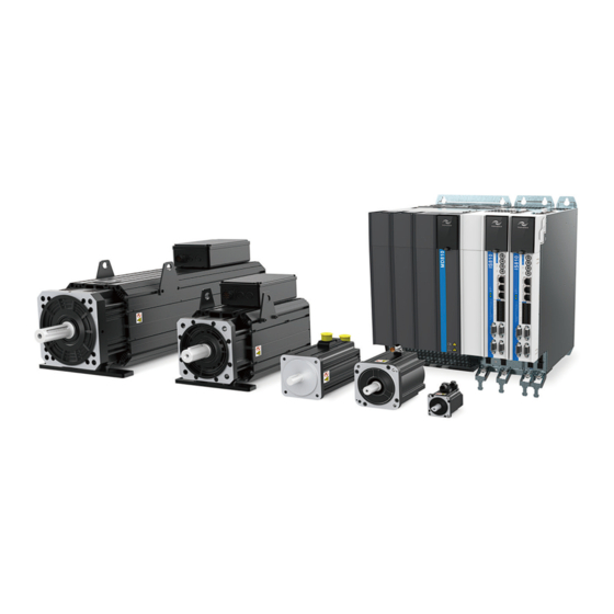
Summary of Contents for Inovance IS810N-INT Series
-
Page 2: Preface
The IS810N-INT series is a high-performance AC servo drive for small and medium power applications. The power of the IS810N-INT series ranges from 100 W to 75 kW. It supports MODBUS, CANopen, and CANlink communication protocols, which allows networking of multiple IS810N-INT drives controlled by a host controller via the corresponding communication port. - Page 3 Install a correct safety device when this product is to be used on machinery which may cause a serious accident or loss due to failures of the product. u Contact Inovance when this product is to be used for atomic energy control, aerospace equipment, transport equipment, medical appliances, safety devices, or other equipment that require high cleanliness.
- Page 4 IS810N-INT Series Servo System User Manual (Brief) Preface § Approvals Certification marks on the product nameplate indicate compliance with the corresponding certificates and standards. Certification Mark Directives Standard AC servo drive EN 61800-3 2014/30/EU directives AC servo motor EN 60034-1...
-
Page 5: Table Of Contents
Contents IS810N-INT Series Servo System User Manual (Brief) Contents Preface ........................2 Chapter 1 Safety Information and Precautions............9 1.1 General Safety ....................9 1.2 Acceptance Precautions ................10 1.3 Storage and Transportation Precautions ............10 1.4 Installation Precautions ..................10 1.5 Wiring Precautions ..................11 1.7 Maintenance Precautions ................12... - Page 6 IS810N-INT Series Servo System User Manual (Brief) Contents Chapter 3 Installation ................... 54 3.1 Power Supply/Drive Unit Installation ..............54 3.1.1 Installation Environment ................54 3.1.2 Product Dimensions and Installation Space Requirements ....56 3.2 Servo Drive Installation ..................61 3.2.1 Cabinet-mounted Installation ..............61 3.2.2 Removal and Installation of a Power Supply Unit Cover ......63...
- Page 7 Contents IS810N-INT Series Servo System User Manual (Brief) 4.6 STO Connection ..................108 4.6.1 Application Example of the STO Function ..........109 4.6.2 Disabling the STO Function ..............110 4.7 RJ45 Communication Connection ..............111 4.8 Control Signal Connection (CN1) ..............112 4.9 Encoder Signal Frequency Division Output and Full Closed-loop Signal Input Connection (CN5/CN7) ............121...
- Page 8 IS810N-INT Series Servo System User Manual (Brief) Contents 6.3 Commissioning Cases .................174 6.3.1 Basic Settings of the AM600 Controller for OMET ....... 174 6.3.2 Basic Settings of the Beckhoff Controller for OMET ......184 6.3.3 Basic Settings of the Omron NJ Controller for OMET ......204 6.3.4 Basic Settings of the Trio Controller for OMET ........214...
-
Page 9: Chapter 1 Safety Information And Precautions
Chapter 1 Safety Information and Precautions IS810N-INT Series Servo System User Manual (Brief) Chapter 1 Safety Information and Precautions This manual includes notices you have to observe in order to ensure your personal safety and prevent property damages. These notices shown below are graded according to the degree of danger. -
Page 10: Acceptance Precautions
IS810N-INT Series Servo System User Manual (Brief) Chapter 1 Safety Information and Precautions 1.2 Acceptance Precautions Item Description Whether the delivered product is The box contains the equipment and the IS810N user consistent with your order guide. Verify the model according to the servo motor and servo drive nameplates. -
Page 11: Wiring Precautions
Chapter 1 Safety Information and Precautions IS810N-INT Series Servo System User Manual (Brief) 1.5 Wiring Precautions CAUTION CAUTION u NEVER connect a power supply to the output terminals U, V, and W of the drive. Failure to comply may result in personal injuries or a fire. -
Page 12: Maintenance Precautions
IS810N-INT Series Servo System User Manual (Brief) Chapter 1 Safety Information and Precautions CAUTION CAUTION 7. Configure safety devices such as circuit breakers to prevent a short-circuit in the external circuit. Failure to comply may result in a fire. u Take appropriate shielding measures in the following scenarios to prevent equipment damages: 1. -
Page 13: Check Item And Period
Replace the servo drive and motor according to the instructions in the following table. If replacement is required, contact the dealer or Inovance first to check whether the components need to be replaced. Object... -
Page 14: Disposal Precautions
Install a proper safety device when this product is to be used on machinery which may cause serious accident or loss due to failures of the product. u Contact Inovance when this product is to be used for atomic energy control, aerospace equipment, transport equipment, medical appliances, safety devices, or other equipment that require high cleanliness. -
Page 15: Chapter 2 Product Information
Chapter 2 Product Information IS810N-INT Series Servo System User Manual (Brief) Chapter 2 Product Information An MD810 power supply unit must be purchased before the use of this product. For information about the specifications of the power supply unit, refer to the User Guide MD810 Series AC Drive Multi-axis System. -
Page 16: Components Of Drive Unit
IS810N-INT Series Servo System User Manual (Brief) Chapter 2 Product Information Figure 2-2 Production serial number of drive unit 01050193 4 H 7 00001 Mark Internal Code Mark Serial Number The 1 set in the current 01****** Machine material code... -
Page 17: Specifications
Maximum output current Arms 92.5 112.5 187.5 227.5 Main circuit power supply 537 to 679 VDC Control circuit power supply 24 VDC, +10% to -10% Note: SIZE-2 and SIZE-3 are being developed. If you have need them, contact Inovance. - 17 -... - Page 18 IS810N-INT Series Servo System User Manual (Brief) Chapter 2 Product Information 2) Basic Specifications Item Description IGBT PWM control, sine wave current drive mode Control mode 380 V: three-phase full-wave rectification Inovance 20-bit serial incremental encoder Encoder feedback Inovance 23-bit serial absolute encoder 0–45°C (Derate it when the temperature...
- Page 19 Chapter 2 Product Information IS810N-INT Series Servo System User Manual (Brief) Item Description 8 DIs (HDI4 and HDI8 being high-speed 37 DI functions: S-ON, fault/warning reset, gain switchover Main/auxiliary running reference switchover, multi-speed DI switchover, running direction selection, multi- reference switchover (4 DIs)
-
Page 20: Servo Motor
IS810N-INT Series Servo System User Manual (Brief) Chapter 2 Product Information Item Description Overcurrent, overvoltage, undervoltage Overload, main circuit detection abnormality Protection functions Heatsink overheat, phase loss, overspeed Encoder abnormality, CPU abnormality, parameter abnormality, and so on. Built-in functions 5-digit LED display indicating the main... - Page 21 Chapter 2 Product Information IS810N-INT Series Servo System User Manual (Brief) Nameplate AC Servo Motor Model: ISMH3-18C15CD-A351B-Om19 Model IEC60034 Pn(kW) Un(V) 380 In(A) 6.6 Parameters Nn(r/min) 1500 Tn(Nm) 11.5 Duty fn(Hz) Ins. EFF. 85.9% IP65 3PH AC Max rev .(r/min) 3000...
- Page 22 IS810N-INT Series Servo System User Manual (Brief) Chapter 2 Product Information These items and torque-speed characteristic values are obtained when the motor works together with Inovance drive units and the armature coil temperature is 20°C. 3) Motor Overload Characteristics Load Ratio (%)
- Page 23 Chapter 2 Product Information IS810N-INT Series Servo System User Manual (Brief) Servo Motor Model Allowed Radial Load (N) Allowed Axial Load (N) ISMH2-20C30CD-A331Y-Om19 ISMH2-20C30CD-A351Y-Om19 ISMH3-56C30CD-A331B-Om24 1176 ISMH3-56C30CD-A351B-Om24 ISMH3-18C15CD-A351B-Om19 ISMH3-18C15CD-A351B-Om24 1. The power supply of the brake must not be shared with other electrical devices. This is to prevent malfunction of the brake due to voltage or current drop that occurs when other electrical devices work.
-
Page 24: Specifications Of The Ismh Servo Motor Series
IS810N-INT Series Servo System User Manual (Brief) Chapter 2 Product Information 2.2.2 Specifications of the ISMH Servo Motor Series 1. Designation Rules and Nameplate Figure 2-6 Designation rules and nameplate of servo motor ISM H1-75B 30C B-A3 3 1 Z... - Page 25 Chapter 2 Product Information IS810N-INT Series Servo System User Manual (Brief) 2. Servo Motor Specifications 1) Motor Mechanical Characteristics Item Description Rated time Continuous Vibration level Insulation resistance 500 VDC, above 10 MΩ Operating temperature 0–40°C Excitation mode Permanent magnetic...
- Page 26 The parameter values in the preceding table are applicable when the motor works together with the Inovance servo drive and the armature coil temperature is 20°C. The preceding table shows the characteristic parameters of the motor after a heatsink below is installed for the motor.
- Page 27 Chapter 2 Product Information IS810N-INT Series Servo System User Manual (Brief) Figure 2-7 Motor overload curve Running time (s) 1000 Load ratio (%) The maximum torque of H1, H2, and H4 are 3 times the rated torque. Except for the 2.9 kW model, the maximum torque of H3 is 2.5 times the rated torque.
- Page 28 IS810N-INT Series Servo System User Manual (Brief) Chapter 2 Product Information Allowed Allowed Allowed Allowed Servo Motor Model Radial Axial Servo Motor Model Radial Axial Load (N) Load (N) Load (N) Load (N) ISMH2-25C30CD-***Y ISMH4-40B30CB-***Z ISMH2-30C30CD-***Y ISMH4-75B30CB-***Z 5) Electrical Specifications of Motors with a Brake...
- Page 29 Chapter 2 Product Information IS810N-INT Series Servo System User Manual (Brief) 6) Motor Torque-Speed Characteristics a) ISMH1 (low inertia, small capacity) Continuous operating area Short-time operating area ISMH1-10B30CB ISMH1-20B30CB 6000 6000 5000 5000 4000 4000 3000 3000 2000 2000 1000 1000 0.25...
- Page 30 IS810N-INT Series Servo System User Manual (Brief) Chapter 2 Product Information b) ISMH2 (low inertia, medium capacity) Continuous operating area Short-time operating area ISMH2-15C30C* ISMH2-10C30C* 6000 5000 5000 4000 4000 3000 3000 2000 2000 1000 1000 Torque (N·m) Torque (N·m)
- Page 31 Chapter 2 Product Information IS810N-INT Series Servo System User Manual (Brief) ISMH2-50C30CD 5000 4000 3000 2000 1000 Torque (N·m) c) ISMH3 (medium inertia, medium capacity) Continuous operating area Short-time operating area ISMH3-13C15C* ISMH3-85B15C* 3500 3500 3000 3000 2500 2500 2000...
- Page 32 IS810N-INT Series Servo System User Manual (Brief) Chapter 2 Product Information ISMH3-44C15CD ISMH3-55C15CD 3500 3000 3000 2500 2000 2000 1500 1000 1000 Torque (N·m) Torque (N·m) ISMH3-75C15CD 3000 2000 1000 Torque (N·m) d) ISMH4 (medium inertia, small capacity) Continuous operating area...
-
Page 33: Specifications Of Ismg The Servo Motor Series
Chapter 2 Product Information IS810N-INT Series Servo System User Manual (Brief) 2.2.3 Specifications of ISMG the Servo Motor Series 1. Designation Rules and Nameplate ISM G1- 30D 15C D–A3 3 1 F A Mark Series Mark Product Code IS series servo... - Page 34 IS810N-INT Series Servo System User Manual (Brief) Chapter 2 Product Information 2. Servo Motor Specifications Table 2-1 Servo motor specifications D-axis Q-axis Voltage Speed Frequency Torque Phase Phase Servo Motor Model Power (kW) Current (A) (RPM) (Hz) (Nm) Inductance Inductance...
- Page 35 2400 397.2 A331F Note: For other motor specifications and models, contact Inovance. 3. Specifications of ISMG Series Motors with a Brake • When deciding the length of the cable on the motor brake side, consider voltage drop caused by the cable resistance. The input voltage must be at least 21.6 V to make the brake work.
- Page 36 IS810N-INT Series Servo System User Manual (Brief) Chapter 2 Product Information Table 2-2 Brake specifications Supply Resistance Holding Supply Current Brake Braking Rotary Servo Motor Torque Voltage Range at Release Time Clearance at 20°C (Ω) Model (Nm) (V) ± 10% 20°C (A)
- Page 37 Chapter 2 Product Information IS810N-INT Series Servo System User Manual (Brief) ISMG1-18D20CD ISMG1-22D15CD 1000 2000 3000 4000 1000 1500 2000 Speed (RPM) Speed (RPM) ISMG1-23D20CD ISMG1-28D20CD 1000 1000 2000 3000 4000 2000 3000 4000 Speed (RPM) Speed (RPM) ISMG1-30D15CD ISMG1-41D20CD...
- Page 38 IS810N-INT Series Servo System User Manual (Brief) Chapter 2 Product Information ISMG2-31D15CD ISMG2-42D20CD 1000 1000 1500 2000 2000 3000 4000 Speed (RPM) Speed (RPM) ISMG2-42D15CD ISMG2-52D15CD 1000 1000 1500 2000 1500 2000 Speed (RPM) Speed (RPM) ISMG2-57D20CD ISMG2-60D15CD 1000 2000...
- Page 39 Chapter 2 Product Information IS810N-INT Series Servo System User Manual (Brief) ISMG2-70D20CD ISMG2-80D20CD 1000 1000 2000 3000 4000 2000 3000 4000 Speed (RPM) Speed (RPM) ISMG2-80D15CD ISMG2-94D15CD 1400 1400 1200 1200 1000 1000 1000 1500 2000 1000 1500 2000 Speed (RPM)
-
Page 40: Specifications Of The Ms1 Servo Motor Series
IS810N-INT Series Servo System User Manual (Brief) Chapter 2 Product Information 2.2.4 Specifications of the MS1 Servo Motor Series 1. Designation Rules and Nameplate Figure 2-10 Designation rules and nameplate of the servo motor series MS1 H1 – 40B 30C B – A3 3 1 Z... - Page 41 The parameter values in the preceding table are applicable when the motor works together with the Inovance servo drive and the armature coil temperature is 20°C. The preceding table shows the characteristic parameters of the motor after the heatsink below is installed for the motor.
- Page 42 IS810N-INT Series Servo System User Manual (Brief) Chapter 2 Product Information 3) Motor Overload Characteristics Load Ratio (%) Running Time (s) Load Ratio (%) Running Time (s) Figure 2-11 Motor overload curve Running time (s) 1000 Load ratio (%) The maximum torque of H1 and H4 is 3.5 times the rated torque.
- Page 43 Chapter 2 Product Information IS810N-INT Series Servo System User Manual (Brief) Servo Motor Model Allowed Radial Load (N) Allowed Axial Load (N) MS1H1-05B30CB-***Z-S MS1H1-10B30CB-***Z-S MS1H1-20B30CB-***Z-S MS1H1-40B30CB-***Z-S MS1H1-55B30CB-***Z-S MS1H1-75B30CB-***Z-S MS1H1-10C30CB-***Z-S MS1H4-40B30CB-***Z-S MS1H4-75B30CB-***Z-S 5) Electrical Specifications of Motors with a Brake Supply...
- Page 44 IS810N-INT Series Servo System User Manual (Brief) Chapter 2 Product Information 6) Motor Torque-Speed Characteristics a) MS1H1 (low inertia, small capacity) Continuous operating area Short-time operating area MS1H1-05B30CB MS1H1-10B30CB Speed (RPM) Speed (RPM) 6000 6000 5000 5000 4000 4000 3000...
- Page 45 Chapter 2 Product Information IS810N-INT Series Servo System User Manual (Brief) MS1H1-55B30CB MS1H1-75B30CB Speed (RPM) Speed (RPM) 6000 6000 5000 5000 4000 4000 3000 3000 2000 2000 1000 1000 Torque (N·m) Torque (N·m) MS1H1-10C30CB Speed (RPM) 6000 5000 4000 3000...
-
Page 46: Servo System Configuration
IS810N-INT Series Servo System User Manual (Brief) Chapter 2 Product Information 2.3 Servo System Configuration Rated Max. Speed Capacity Motor Drive SN Speed Servo Motor Model Drive Model Drive Size (RPM) (kW) Frame (H01-10) (RPM) ISMH3-18C15CD-A351B-Om19 1500 3000 ISMH3-18C15CD-A351B-Om24 ISMH2-20C30CD-A351Y-Om19... - Page 47 Chapter 2 Product Information IS810N-INT Series Servo System User Manual (Brief) Rated Max. Speed Capacity Motor Drive SN Speed Servo Motor Model Drive Model Drive Size (RPM) (kW) Frame (H01-10) (RPM) 1500 1830 ISMG1-95C15CD-A331FA IS810N50M4TD017INT 10005 2000 2560 10.5 ISMG1-12D20CD-A331FA...
-
Page 48: Applicable Cables
(above 2.9 kW) S6-L-P021-3.0 S6-L-P021-5.0 S6-L-P021-10.0 cable Note: The servo motor encoder cable does not include a CN1 (DB15) connector. Please purchase it separately. The model is S6-C6. If you select Inovance matching cables, no connector kit is required. - 48 -... - Page 49 (above 2.9 kW) S6-L-P021-3.0 S6-L-P021-5.0 S6-L-P021-10.0 cable Note: The servo motor encoder cable does not include a CN1(DB15)connector. Please purchase it separately. The model is S6-C6. If you select Inovance matching cables, no connector kit is required. - 49 -...
- Page 50 If you select Inovance matching cables, no connector kit is required. Battery Kit of Absolute Encoder Motor If an Inovance absolute encoder motor is used, the optional battery kit S6-C4 (battery and battery box) is required besides the applicable cables.
-
Page 51: Cables Applicable For Ismg Series Servo Motors (Communication Cables Included)
Chapter 2 Product Information IS810N-INT Series Servo System User Manual (Brief) 2.4.3 Cables Applicable for ISMG Series Servo Motors (Communication Cables Included) Table 2-7 Servo motor cable Servo motor encoder cable Item L = 3.0m L = 5.0m L = 10.0m ISMG1(G2)-*******-A3*** S6-L-P021-3.0... -
Page 52: Cables Applicable For Ms1H Series Servo Motors (Communication Cables Included)
Absolute encoder S6-L-P020-3.0 S6-L-P020-5.0 S6-L-P020-10.0 cable If you select Inovance matching cables, no connector kit is required. Table 2-12 Cables applicable for models with a brake Servo Motor Power Cable and Encoder Cable (Models Without a Brake) Motor Model Cable Type L = 3.0 m... -
Page 53: Servo System Wiring
Chapter 2 Product Information IS810N-INT Series Servo System User Manual (Brief) 2.5 Servo System Wiring Figure 2-13 Wiring of a three-phase 380 V system Power Supply Three-phase 380 VAC Circuit breaker for wiring Used to protect the power cable and cut off the circuit during overcurrent. -
Page 54: Chapter 3 Installation
IS810N-INT Series Servo System User Manual (Brief) Chapter 3 Installation Chapter 3 Installation 3.1 Power Supply/Drive Unit Installation 3.1.1 Installation Environment • Installation location 1) Ambient temperature: Ambient temperature has a great effect on the AC drive life. The operating temperature of the AC drive shall not exceed the allowable temperature range (-10°C to 50°C). - Page 55 Chapter 3 Installation IS810N-INT Series Servo System User Manual (Brief) • Environmental conditions Table 3-1 Installation environment Item Description Operating temperature: -10 to 50°C, air temperature change: less than 0.5°C/min; derated when the temperature is higher than 40°C, 1.5% deration of rated current per 1°C temperature rise; maximum temperature: 50°C...
-
Page 56: Product Dimensions And Installation Space Requirements
IS810N-INT Series Servo System User Manual (Brief) Chapter 3 Installation 3.1.2 Product Dimensions and Installation Space Requirements I. Product Dimensions (mm) 1) Power Supply Unit Figure 3-2 MD810-20M4T**G*** overall dimensions H H1 H2 100 mm 200 mm 300 mm 300 mm water cooled... - Page 57 Chapter 3 Installation IS810N-INT Series Servo System User Manual (Brief) Model Dimensions Voltage class MD810-20M4T***G***(W) [H]: 350 mm [H1]: 384 mm [H2]: 400 mm [W]: 100 mm [W1]: 50 mm [D]: 305 mm [H]: 350 mm [H1]: 384 mm [H2]: 400 mm...
- Page 58 IS810N-INT Series Servo System User Manual (Brief) Chapter 3 Installation 2) Drive unit Figure 3-3 IS810N50M4T****INT (SIZE 1) overall dimensions Front view Left view Top view Figure 3-4 IS810N50M4T****INT (SIZE 2) overall dimensions Top view Left view Top view - 58 -...
- Page 59 Chapter 3 Installation IS810N-INT Series Servo System User Manual (Brief) Figure 3-5 IS810N50M4T****INT (SIZE 3) overall dimensions Front view Left view Top view II. Space Requirements Power supply units are divided into book-type units (100 mm, 200 mm and 300 mm wide) and vertical units (180 mm wide).
- Page 60 IS810N-INT Series Servo System User Manual (Brief) Chapter 3 Installation Figure 3-6 Space for two-layer installation of a book-type power supply unit Thermal insulation deflector 2200 ≥500 Figure 3-7 Space for two-layer installation of a vertical power supply unit 2200 ≥500...
-
Page 61: Servo Drive Installation
Chapter 3 Installation IS810N-INT Series Servo System User Manual (Brief) 3.2 Servo Drive Installation 3.2.1 Cabinet-mounted Installation This product can be installed in a cabinet in a single-row or two-row installation manner. A book-type unit must be installed closely to avoid product damages during transportation. Do not install merely two or less servo drives. - Page 62 IS810N-INT Series Servo System User Manual (Brief) Chapter 3 Installation Two-row installation Book-type unit Vertical unit Thermal Thermal insulation insulation deflector deflector Thermal Thermal insulation insulation deflector deflector Note: An insulation deflector may be installed on the upper unit layer in two-row installation.
-
Page 63: Removal And Installation Of A Power Supply Unit Cover
Chapter 3 Installation IS810N-INT Series Servo System User Manual (Brief) 3.2.2 Removal and Installation of a Power Supply Unit Cover Cover Removal Lift the translucent keypad Remove the upper cover by Pull the whole keypad box cover. Loosen the screws rotating it forward. - Page 64 IS810N-INT Series Servo System User Manual (Brief) Chapter 3 Installation Cover Removal Align the power terminal cover Insert the keypad. Align the upper cover with the with the clip of the bus seat. clip. Press the upper cover to Press the power terminal fix it.
-
Page 65: Wall-Mounted Installation
Chapter 3 Installation IS810N-INT Series Servo System User Manual (Brief) 3.2.3 Wall-Mounted Installation Recommended torque (N.m) for installation: Item Electric 0.55 connection Ensure that there is enough product installation space on the left of the power supply unit. A multi-axis system requires units to be lined up along the top. - Page 66 IS810N-INT Series Servo System User Manual (Brief) Chapter 3 Installation ● Cooling Make sure that the servo drive is installed vertical to the wall. Cool the servo drive with natural convection or a cooling fan. As shown in the preceding figure, keep sufficient space around the servo drive to ensure cooling by fans or natural convection.
-
Page 67: Servo Motor Installation
Chapter 3 Installation IS810N-INT Series Servo System User Manual (Brief) 3.3 Servo Motor Installation 3.3.1 Installation Precautions Install the servo drive in an environment free from corrosive or inflammable gas or combustible goods, such as hydrogen sulfide, chlorine, ammonia, sulphur gas, chlorinated gas, acid, soda and salt;... - Page 68 IS810N-INT Series Servo System User Manual (Brief) Chapter 3 Installation Item Description u Use the shaft coupling for mechanical connection and align the axis of the servo motor with the axis of the equipment. When installing the servo motor, make sure that alignment accuracy satisfies the requirements as described in the figure to the left.
- Page 69 Chapter 3 Installation IS810N-INT Series Servo System User Manual (Brief) Item Description Observe the following precautions: u When connecting the connectors, make sure that there is no foreign matter such as waste or sheet metal inside the connectors. u Connect the connectors to the main circuit side of the servo motor first, and make sure that the grounding cable of the power cables is properly connected.
-
Page 70: Installation Environment
IS810N-INT Series Servo System User Manual (Brief) Chapter 3 Installation 3.3.2 Installation Environment Table 3-3 Installation environment OneCable Item ISMH Series Motor MS1H Series Motor Servo Motor 0°C to 40°C (non-freezing). Please perform deration at over 40°C based on the following coefficients:... -
Page 71: Overall Dimensions Of The Ismh Servo Motor Series
Chapter 3 Installation IS810N-INT Series Servo System User Manual (Brief) 43.70 0.10 A 50.50 φ 145 4×R21 9× φ9 RH 0 -0.20 -0.09 Shaft end Flat key Weight Model (mm) (mm) (mm) (mm) (mm) (mm) (mm) (mm) (mm) (mm) (kg) ISMH3-18C15CD- M6×18... - Page 72 IS810N-INT Series Servo System User Manual (Brief) Chapter 3 Installation Motor model Weight (kg) ISMH1-10B30CB-***Z M3×6 0.59 (0.77) -0.1 ISMH1-20B30CB-****Z M5×8 16.5 1.1 (1.4) -0.1 ISMH1-40B30CB-****Z M5×8 16.5 -0.1 ISMH1-55B30CB-****Z M6×20 15.5 -0.1 ISMH1-75B30CB-****Z M6×20 15.5 -0.1 ISMH1-10C30CB-****Z M6×20 15.5 -0.1...
- Page 73 Chapter 3 Installation IS810N-INT Series Servo System User Manual (Brief) Motor Model KB1 KA2 ISMH2-10C30CB- 94.5 143.5 164 (213.5) 45±1 4-φ7 **3*Y (101) (192.5) ISMH2-15C30CB- 119.5 168.5 189 (239) 45±1 4-φ7 **3*Y (128) (219.5) ISMH2-10C30CD- 94.5 143.5 164 (213.5) 45±1 4-φ7...
- Page 74 IS810N-INT Series Servo System User Manual (Brief) Chapter 3 Installation 3) Overall Dimensions of the ISMH3 Servo Motor Series (850 W, 1.3 kW, 1.8 kW) 0.10 A Φ0.06 φLA φS h6 0.03 KW N9 W h8 T h11 Shaft end dimensions...
- Page 75 Chapter 3 Installation IS810N-INT Series Servo System User Manual (Brief) 4) Overall Dimensions of the ISMH3 Servo Motor Series (2.9 kW, 4.4 kW, 5.5 kW, 7.5 kW) 0.10 A Φ0.06 φLA φS h6 KW N9 W h8 T h11 Shaft end dimensions...
- Page 76 IS810N-INT Series Servo System User Manual (Brief) Chapter 3 Installation 5) Overall Dimensions of the ISMH4 Servo Motor Series (400 W, 750 W) φLA φSh6 KW N9 W h8 T h8 Shaft end dimensions Keyed shaft end dimensions Motor Model...
-
Page 77: Overall Dimensions Of The Ismg Servo Motor Series
ISMG1-41D20CD-A331FA Note: The standard is A3 series. If you require R1 or U1 series, contact Inovance for customization. The mounting baseplate is optional, and used only for ISMG1-22D15CD-A331FA and ISMG1- 30D15CD-A331FA or when required. A K value indicates the mounting baseplate clearance. - Page 78 ISMG2-52D15CD-A331FA 158.4 ISMG2-70D20CD-A331FA ISMG2-60D15CD-A331FA 175.4 ISMG2-80D20CD-A331FA ISMG2-80D15CD-A331FA ISMG2-11E20CD-A331FA ISMG2-94D15CD-A331FA Note: The standard is A3 series. If you require R1, U1 or U2 series, contact Inovance for customization. The mounting baseplate is optional, and used only when required. - 78 -...
-
Page 79: Overall Dimensions Of The Ms1H Servo Motor Series
Chapter 3 Installation IS810N-INT Series Servo System User Manual (Brief) 3.3.6 Overall Dimensions of the MS1H Servo Motor Series Shaft end Shaft end keyed Motor Model MS1H1-05B30CB-A330Z-S 25±5.5 2-φ-.5 2.5H1-0. 0.5±0.35 MS1H1-05B30CB-A332Z-S 251H1- 2-1H1- 2.5H1-0. 0.5±0.35 MS1H1-10B30CB-A330Z-S 77.5 25±5.5 2-φ-.5 2.551-1: 0.5±0.35... - Page 80 IS810N-INT Series Servo System User Manual (Brief) Chapter 3 Installation Weight Motor model (kg) MS1H1-05B30CB-A330Z-S M3×3 15.5 -0.1 MS1H1-05B30CB-A332Z-S M31H 15.5 -0.1 MS1H1-10B30CB-A330Z-S M3×3 15.5 -0.1 MS1H1-10B30CB-A332Z-S M31H 15.5 -0.1 MS1H1-20B30CB-A331Z-S M5×5 16.5 -0.1 MS1H1-20B30CB-A334Z-S M51H 16.5 -0.1 MS1H1-40B30CB-A331Z-S M5×5 16.5...
-
Page 81: Chapter 4 Wiring
Chapter 4 Wiring IS810N-INT Series Servo System User Manual (Brief) Chapter 4 Wiring DANGER Wiring must be performed by authorized and qualified personnel. Before removing or installing the drive, turn off the power, wait five minutes until the power indicator becomes off, and verify that the voltage between and Θ is zero using a multimeter. -
Page 82: Terminals In A Power Supply Unit
IS810N-INT Series Servo System User Manual (Brief) Chapter 4 Wiring For the power supply and the main circuit connection, make sure that the main circuit power supply is cut off and the servo changes from the ON state to the OFF state after the alarm signal is detected. -
Page 83: Function Description Of Terminals In Drive Unit
Chapter 4 Wiring IS810N-INT Series Servo System User Manual (Brief) 4.2.2 Function Description of Terminals in Drive Unit Table 4-1 Terminal names and functions Terminal Terminal Name Terminal Function Symbol +, - Power input terminals Bus input Connected to the U, V and W phases of... -
Page 84: Connection Of The Power Supply Unit To The Drive Unit
IS810N-INT Series Servo System User Manual (Brief) Chapter 4 Wiring 4.3 Connection of the Power Supply Unit to the Drive Unit 4.3.1 Power Connection Through the DC Bus Remove the display cover of the drive unit. Connect the power supply unit to the drive unit with the DC busbar. -
Page 85: Pe Connection
Chapter 4 Wiring IS810N-INT Series Servo System User Manual (Brief) 4.3.2 PE Connection Properly ground every device in the system! Connect the power supply unit, drive unit, and components such as the filter and reactor to the PE copper bar in the cabinet using the star... -
Page 86: Control Power Supply
IS810N-INT Series Servo System User Manual (Brief) Chapter 4 Wiring 4.3.3 24 V Control Power Supply The power supply of the drive unit is divided into the control part and the power part. The control part is preferentially powered by the DC busbar that is connected to the power supply unit. -
Page 87: Shield Grounding And Hose Clamp
Chapter 4 Wiring IS810N-INT Series Servo System User Manual (Brief) 4.3.4 Shield Grounding and Hose Clamp To ensure device stability, fix the exposed shield of cables to the shield support with a hose clamp to ensure grounding of the shield, as shown in the following figure. -
Page 88: Connection Of The Drive Unit To The Motor
IS810N-INT Series Servo System User Manual (Brief) Chapter 4 Wiring 4.4 Connection of the Drive Unit to the Motor 4.4.1 Grounding Requirements Properly ground the PEs of the servo drive and servo motor. 4.4.2 Connection to a OneCable Series Servo Motor... - Page 89 Chapter 4 Wiring IS810N-INT Series Servo System User Manual (Brief) Table 4-2 Connectors of OneCable cables on the servo motor side Connector Appearance Terminal Pin Layout Frame Size of Applicable Motor Pin No. Signal Color Blue Black Yellow/ Green +5 V...
-
Page 90: Connection To An Ismh Series Servo Motor
IS810N-INT Series Servo System User Manual (Brief) Chapter 4 Wiring 4.4.3 Connection to an ISMH Series Servo Motor 1. Power Cable Connection Figure 4-6 Example of servo drive output connection to the servo motor Table 4-3 Connectors of power cables on the servo motor side... - Page 91 Chapter 4 Wiring IS810N-INT Series Servo System User Manual (Brief) Connector Frame Size of Terminal Pin Layout Appearance Applicable Motor MIL-DTL-5015 series 3108E20-22S military spec. 20-22 military spec. Y Series Terminal Z Series Terminal Definition Definition Color Pin No. Signal Pin No.
- Page 92 IS810N-INT Series Servo System User Manual (Brief) Chapter 4 Wiring Connector Frame Size of Terminal Pin Layout Appearance Applicable Motor 4-pin connector 40 (X series) Pin No. Signal Color 60 (X series) Blue 80 (X series) Black Yellow/Green Recommendation: Plastic housing: Zhejiang CWB EL-4A;...
- Page 93 Chapter 4 Wiring IS810N-INT Series Servo System User Manual (Brief) Table 4-4 Connectors of IS810N series 20-bit encoder cables on servo drive side Connector Appearance Terminal Pin Layout Pin No. Signal Viewed from +5 V this side Housing Recommendation: Plastic housing of plug on cable side: DB9P...
- Page 94 Cable Size Ω/km Allowed Cable Length (m) 26AWG (0.13 mm2) 10.0 25AWG (0.15mm2) 89.4 16.0 24AWG (0.21mm2) 79.6 18.0 23AWG (0.26mm2) 68.5 20.9 22AWG (0.32mm2) 54.3 26.4 If cables sized greater than 22AWG are required, contact Inovance. - 94 -...
- Page 95 Chapter 4 Wiring IS810N-INT Series Servo System User Manual (Brief) ● Absolute Encoder Installation Installation of the Battery Box for the Absolute Encoder Battery box model (optional): S6-C4 This model includes: One sheet metal bracket One plastic box One 3.6 V/2600 mAh battery...
- Page 96 IS810N-INT Series Servo System User Manual (Brief) Chapter 4 Wiring When closing the battery box cover, prevent the connector cables from being pinched. Note: Improper use of a battery may result in battery leakage which will corrode the components or cause the battery to explode. Observe the following precautions during use: •...
- Page 97 Chapter 4 Wiring IS810N-INT Series Servo System User Manual (Brief) Note 1: During normal operation, the absolute encoder supports one-turn or multiturn data counting and transmitting/receiving. After connecting the absolute encoder properly, turn on the power to the servo drive, and the encoder enters normal operation state and transmits/ receives data after a delay of 5s.
- Page 98 IS810N-INT Series Servo System User Manual (Brief) Chapter 4 Wiring 2. Wiring of Battery Box and Signal Wires Figure 4-9 Example of wiring of the battery box and signal wires for an absolute encoder Color of the battery box outer lead:...
- Page 99 Chapter 4 Wiring IS810N-INT Series Servo System User Manual (Brief) Table 4-11 Connectors of IS810N series absolute encoder cables (MIL-DTL-5015 series 3108E20-29S military spec.) Frame Size of Connector Appearance and Pin Layout Applicable Motor Encoder connection socket Encoder cable connector...
- Page 100 IS810N-INT Series Servo System User Manual (Brief) Chapter 4 Wiring Table 4-12 Connectors of IS810N series absolute encoder cables (9-pin connector) Frame Size of Connector Appearance and Pin Layout Applicable Motor Encoder cable Encoder cable connector connector Connect to CN2 of...
-
Page 101: Connection To An Ismg Series Servo Motor
Chapter 4 Wiring IS810N-INT Series Servo System User Manual (Brief) 4.4.4 Connection to an ISMG Series Servo Motor 1. Power Cable Connection Figure 4-11 Example of drive unit output connection to an ISMG series servo motor Effect diagram after fixing is... - Page 102 IS810N-INT Series Servo System User Manual (Brief) Chapter 4 Wiring Ground the shield correctly. It is recommended that the drive be installed on a metal mounting surface and ensure proper contact between the conductive base of the drive and the metal mounting surface.
- Page 103 Chapter 4 Wiring IS810N-INT Series Servo System User Manual (Brief) Table 4-14 Connectors of encoder cables on the servo motor side Connector Appearance Terminal Pin Layout MIL-DTL-5015 series 3108E20-29S military spec. 20-29 military spec. Viewed from this side Pin No.
- Page 104 IS810N-INT Series Servo System User Manual (Brief) Chapter 4 Wiring Table 4-16 Recommended cable sizes Cable Size Ω/km Allowed Cable Length (m) 26AWG (0.13 mm 10.0 25AWG (0.15 mm 89.4 16.0 24AWG (0.21 mm 79.6 18.0 23AWG (0.26 mm 68.5 20.9...
-
Page 105: Connection To An Ms1H Series Servo Motor
Chapter 4 Wiring IS810N-INT Series Servo System User Manual (Brief) 4.4.5 Connection to an MS1H Series Servo Motor 1. Power Cable Connection Table 4-17 Connectors of power cables on the servo motor side Frame Size of Connector Appearance Terminal Pin Layout... -
Page 106: Brake Wiring
IS810N-INT Series Servo System User Manual (Brief) Chapter 4 Wiring 4.5 Brake Wiring A brake is used to lock the motor in position when the servo drive is shut down to prevent the moving part of the machine from falling by gravity or being moved by external force. - Page 107 Chapter 4 Wiring IS810N-INT Series Servo System User Manual (Brief) Caution Use this built-in brake to keep the stalling status only. Never use this for "Brake" to stop the load in motion. Brake coils are of no polarity. Turn off S-ON after the servo motor stops.
-
Page 108: Sto Connection
IS810N-INT Series Servo System User Manual (Brief) Chapter 4 Wiring 4.6 STO Connection When a fault is detected in the safety circuit, the STO function immediately cuts off the output current of the controller and stops the output torque of the motor. -
Page 109: Application Example Of The Sto Function
Chapter 4 Wiring IS810N-INT Series Servo System User Manual (Brief) 4.6.1 Application Example of the STO Function Figure 4-18 Example 1 Emergency (double Category 3 IEC 13849 stop button contact) 24 V STO1+ Max. SIL 3 PL e NOTE: THE FINAL SYSTEM PL... -
Page 110: Disabling The Sto Function
IS810N-INT Series Servo System User Manual (Brief) Chapter 4 Wiring 4.6.2 Disabling the STO Function When the STO function is not used, an external 24 V power supply must be connected. The following figure shows the specific wiring method of every drive. If multiple drives provide the STO function, the STO terminal of every drive must be connected to an external 24 V switching-mode power supply. -
Page 111: Rj45 Communication Connection
LCD keypad to the RJ45B interface at the top of IS810 using a standard network cable. The figure shows the interface of IS810. The smart operating keypad (model SOP-20) is Inovance's new-generation commissioning assistant for the frequency control system and supports products such as IS810, MD810, MD880 and HE series and vehicle electronic drives. -
Page 112: Control Signal Connection (Cn1)
IS810N-INT Series Servo System User Manual (Brief) Chapter 4 Wiring 4.8 Control Signal Connection (CN1) Figure 4-25 Pin layout of the control circuit terminal connector of a servo drive Axis2 Axis1 +24V +24V COM- COM- COM+ COM+ DO2+ DO1+ DO2-... - Page 113 Chapter 4 Wiring IS810N-INT Series Servo System User Manual (Brief) 2) Wiring 1) DI circuit DI1 to DI3 interface circuits are the same. The following takes DI1 circuit as an example. a) When the host controller provides relay output: If the internal 24 V power supply of the servo drive is used:...
- Page 114 IS810N-INT Series Servo System User Manual (Brief) Chapter 4 Wiring b) When the host controller provides OC output: If the internal 24 V power supply of the servo drive is used: Servo drive Servo drive power power supply supply ...
- Page 115 Chapter 4 Wiring IS810N-INT Series Servo System User Manual (Brief) 2) DO circuit DO1–DO2 interface circuits are the same. The following takes DO1 interface circuit as an example. a) When the host controller provides relay input: Servo drive External 5-24 VDC...
- Page 116 IS810N-INT Series Servo System User Manual (Brief) Chapter 4 Wiring b) When the host controller provides optocoupler input: Servo drive Servo drive External 5-24 VDC External 5-24 VDC No current limiting resistor Optoco is connected upler Optocoupler External 0 V...
- Page 117 Chapter 4 Wiring IS810N-INT Series Servo System User Manual (Brief) b) OC mode When the internal 24 V power supply of the servo drive is used: Host controller Servo drive Host controller Servo drive +24 V power supply Wrong connection: Pin COM- is not connected, which causes an open circuit.
- Page 118 IS810N-INT Series Servo System User Manual (Brief) Chapter 4 Wiring When the external power supply is used: Scheme 1: Using the internal resistor of the drive (recommended) Host controller Servo drive External +24 VDC External 0 V Host controller...
- Page 119 Chapter 4 Wiring IS810N-INT Series Servo System User Manual (Brief) Scheme 2: Using an external resistor Host controller Servo drive External +24 VDC External 0 V Host controller Servo drive External +24 VDC External 0 V - 119 -...
- Page 120 IS810N-INT Series Servo System User Manual (Brief) Chapter 4 Wiring Value of resistor R1 is calculated according to the following formula: Table 4-18 Recommended R1 resistance values VCC Voltage R1 Resistance Value R1 Power 24 V 2.4 kΩ 0.5 W 12 V 1.5 kΩ...
-
Page 121: Encoder Signal Frequency Division Output And Full Closed-Loop Signal Input Connection (Cn5/Cn7)
Chapter 4 Wiring IS810N-INT Series Servo System User Manual (Brief) 4.9 Encoder Signal Frequency Division Output and Full Closed-loop Signal Input Connection (CN5/CN7) Figure 4-26 CN5/CN7 terminal CN5/CN7 PZO- PAO+ PAO- PZO+ PBO+ PBO- 1. Terminal CN5/CN7/DB15 Definition Signal Default Function Pin No. - Page 122 IS810N-INT Series Servo System User Manual (Brief) Chapter 4 Wiring Servo drive Host controller Max. output current 20 mA Caution Connect the 5 V grounding terminal of the host controller to the GND terminal of the servo drive, and use shielded twisted-pair cables to reduce noise interference.
-
Page 123: Communication Signal Connection (Cn3/Cn4)
Chapter 4 Wiring IS810N-INT Series Servo System User Manual (Brief) 4.10 Communication Signal Connection (CN3/CN4) 1. Communication Networking and Terminals Figure 4-27 Communication wiring Figure 4-28 Communication wiring Communication cable for multi-drive-unit parallel connection Drive unit to PLC communication cable... - Page 124 ● Selection principle Specification Supplier 0.2 m to 10 m Inovance Longer than 10 m Haituo ● Basic information about EtherCAT communication cables of Inovance 1) Cable models are as follows: S6-L-T04-3.0 Mark Product Series Cable Length (Unit: m) Mark...
- Page 125 S6-L-T04-2.0 15041964 S6-L-T04-5.0 15041965 S6-L-T04-10.0 10.0 Cables of 10 m long or shorter must be purchased from Inovance. Cables longer than 10 m shall be purchased from Haituo. 3) Specifications and characteristics: Item Detailed Description UL certification Comply with UL certification CAT.5E cable...
- Page 126 IS810N-INT Series Servo System User Manual (Brief) Chapter 4 Wiring 4.11 Communication Connection to PC (CN2) Arrangement of Ethernet(CN2) terminals: Figure 4-29 Ethernet connector terminal - 126 -...
- Page 127 Chapter 4 Wiring IS810N-INT Series Servo System User Manual (Brief) Table 4-20 Pin definition of communication signal terminal connectors Terminal Symbol Pin Description Pin Layout Ethernet Connection Function and No. Definition Specification Data transmit+ Data transmit- Data receive+ Data receive–...
-
Page 128: Anti-Interference Measures For Electrical Wiring
IS810N-INT Series Servo System User Manual (Brief) Chapter 4 Wiring 4.12 Anti-interference Measures for Electrical Wiring Take the following measures to suppress interference: • Ensure that the length of the reference input cable is below 3 m, and the length of the encoder cable is below 20 m. -
Page 129: Using Noise Filter
Chapter 4 Wiring IS810N-INT Series Servo System User Manual (Brief) 4.12.2 Using Noise Filter To prevent interference from power cables and reduce impact of the servo drive on other sensitive devices, install a noise filter on the input side of the power supply according to the input current. -
Page 130: Cablen Use Precautions
IS810N-INT Series Servo System User Manual (Brief) Chapter 4 Wiring Grounding the noise filter inside the cabinet If the noise filter and the servo drive are installed in the same cabinet, fix the noise filter and the servo drive on the same metal plate. Make sure that the contact part is in good conductive condition, and ground the metal plate properly. -
Page 131: General Wiring Diagram
Chapter 4 Wiring IS810N-INT Series Servo System User Manual (Brief) 4.14 General Wiring Diagram Refer to Appendix 2 "General Wiring Diagram". Note 1: CAT5E double shielded or better network cables are recommended. Both direct- through and crossover Ethernet cables are allowed. -
Page 132: Chapter 5 Keypad
IS810N-INT Series Servo System User Manual (Brief) Chapter 5 Keypad Chapter 5 Keypad 5.1 Introduction to LED Keypad Figure 5-1 LED keypad appearance Function indicator ERR/TC TUNE LED display area Operating keys SHIFT ENTER MODE CHARGE The keypad consists of the 5-digit 7-segment LEDs and keys. The keypad is used for display, parameter setting, user password setting and general functions operations. - Page 133 Chapter 5 Keypad IS810N-INT Series Servo System User Manual (Brief) 2. LED Display Area There are 5-digit LEDs on the LED keypad to display status, parameters, faults, and monitoring information. Table 5-2 LED display and actual data - 133 -...
- Page 134 IS810N-INT Series Servo System User Manual (Brief) Chapter 5 Keypad 3. Function Indicator - 134 -...
-
Page 135: Keypad Display
Chapter 5 Keypad IS810N-INT Series Servo System User Manual (Brief) 5.2 Keypad Display ● Conversion Between Keypad Display and Host Controller Operation Objects The mapping between the parameter numbers displayed on the keypad and the object dictionary (hexadecimal index and subindex) operated on the host controller is as follows: Object dictionary index = 0x2000 + Parameter group No. - Page 136 IS810N-INT Series Servo System User Manual (Brief) Chapter 5 Keypad Display Name Condition Meaning Parameter display interface after The parameters currently Operating axis selecting an axis displayed on the operation panel (example) using the axis 1 or are parameters of axis 2.
- Page 137 Chapter 5 Keypad IS810N-INT Series Servo System User Manual (Brief) 2. Parameter Display (Take the parameter of the operating axis 2 as an example) The IS810N series servo drive has 14 function groups based on parameter functions. A function code can be located quickly based on the group it belongs to. For the function code table, refer to chapter 8.
- Page 138 IS810N-INT Series Servo System User Manual (Brief) Chapter 5 Keypad For example, 1073741824 is displayed as follows: Figure 5-4 Display of 1073741824 Segment "–" in the first left LED indicates the current page Low 4 digits Page 1 Middle 4 digits...
- Page 139 Chapter 5 Keypad IS810N-INT Series Servo System User Manual (Brief) 3. Fault Display (Take the parameter of the current operation axis 2 as an example) ● The keypad displays the current or historical faults and warning codes. For analysis and rectification of faults and warnings, refer to Chapter 9.
-
Page 140: Monitoring Parameters
IS810N-INT Series Servo System User Manual (Brief) Chapter 5 Keypad 5.3 Monitoring Parameters Group H0B: Displays the parameters for monitoring the running status of the servo drive. Group H0B monitoring display is described as follows (Take the parameter of the current... - Page 141 Chapter 5 Keypad IS810N-INT Series Servo System User Manual (Brief) Function Name Unit Meaning Display Example Code For example, if DO1 is It displays the level states optocoupler ON and DO2 is of the two DO terminals: high level: If the upper LED segment The binary value is 10;...
- Page 142 IS810N-INT Series Servo System User Manual (Brief) Chapter 5 Keypad Function Name Unit Meaning Display Example Code 100.0% display: It displays the percentage Average load of the average load H0B-12 0.1% ratio torque to the rated motor torque. 10000 encoder unit display:...
- Page 143 Chapter 5 Keypad IS810N-INT Series Servo System User Manual (Brief) Function Name Unit Meaning Display Example Code 4.60 A display: It displays the effective Phase current H0B-24 0.01 A phase current value of effective value the servo motor. 540.0 V display rectified from...
- Page 144 IS810N-INT Series Servo System User Manual (Brief) Chapter 5 Keypad Function Name Unit Meaning Display Example Code If H0B-34=E2.941, H0B-35=107374182.4 , the current fault code is 941 and the total servo running time is 107,374,182.4s when this fault occurs. It indicates the total servo...
- Page 145 Chapter 5 Keypad IS810N-INT Series Servo System User Manual (Brief) Function Name Unit Meaning Display Example Code It displays the high/low For example, the value level state of the 8 DI of H0B-41 read by the terminals when the fault background software is 0x31.
- Page 146 IS810N-INT Series Servo System User Manual (Brief) Chapter 5 Keypad Function Name Unit Meaning Display Example Code 3000.0 RPM display: It displays the actual Actual motor H0B-55 0.1 RPM motor speed, in the unit speed -3000.0 RPM of 0.1 RPM.
- Page 147 Chapter 5 Keypad IS810N-INT Series Servo System User Manual (Brief) Function Name Unit Meaning Display Example Code Example: 32767 Number of It displays the current H0B-70 the absolute number of the absolute encoder turns encoder turns. Example: 8388607 encoder unit...
- Page 148 IS810N-INT Series Servo System User Manual (Brief) Chapter 5 Keypad Function Name Unit Meaning Display Example Code Example: 2147483647 encoder unit It displays the low Rotating 32-bit data of the position load single- feedback of the rotating H0B-81 turn position...
-
Page 149: Parameter Setting
Chapter 5 Keypad IS810N-INT Series Servo System User Manual (Brief) 5.4 Parameter Setting Parameter setting can be performed on the keypad of a servo drive. For details on the parameters, refer to Chapter 8. The following figure shows the keypad operation of switching the position control mode to the speed control mode after the power is on. -
Page 150: User Password
IS810N-INT Series Servo System User Manual (Brief) Chapter 5 Keypad 5.5 User Password After the user password function (H02-30) is enabled, only the authorized user is allowed to set parameters; other operators can only view the parameters. 1) Setting a user password The following figure shows the operation procedure of setting the password to "00001". -
Page 151: Jog Running
Chapter 5 Keypad IS810N-INT Series Servo System User Manual (Brief) 5.6 Jog Running Caution When using the jog running function, set the S-ON signal inactive. Otherwise, this function cannot be used. Use the jog running function to perform a trial run on the servo motor and drive. -
Page 152: Di/Do Function
IS810N-INT Series Servo System User Manual (Brief) Chapter 5 Keypad 5.7 DI/DO Function There are eight DI signals and two DO signals on terminal CN1 of SV820N. H03 (terminal DI function allocation and logic selection) and H04 (terminal DO function allocation and logic selection) can be used by multiple axes. - Page 153 Chapter 5 Keypad IS810N-INT Series Servo System User Manual (Brief) Function Function Description Remarks Symbol Name Output Signal Function Description Valid - Servo is ready. Servo S-RDY Servo is ready can can be run. Invalid - Servo is not ready ready.
- Page 154 IS810N-INT Series Servo System User Manual (Brief) Chapter 5 Keypad Example: Set DI1 and DI2 as the home signals of 2 modules respectively. The corresponding parameters can be set as follows via background software or the keypad: H0302 = 131...
-
Page 155: Chapter 6 Commissioning Software
Chapter 6 Commissioning Software IS810N-INT Series Servo System User Manual (Brief) Chapter 6 Commissioning Software 6.1 Basic Setting Figure 6-1 Servo drive setting procedure Star • Check the wiring. Check before • Check the environment and running mechanical conditions. Power supply •... -
Page 156: Check Before Run
6.1.3 Jogging Perform jogging to check whether the motor can rotate properly without abnormal vibration or noise. This operation can be performed via the keypad in speed mode, Inovance servo commissioning software in speed mode and keypad in position mode. - Page 157 IS810N-INT Series Servo System User Manual (Brief) 2) Jogging via the Inovance servo commissioning software in speed mode Open the Inovance servo commissioning software > Special servo function > Speed jog operating interface. Switch the drive to the non-bus control mode (H02-00 is not 9). After selecting a corresponding axis from Axis selection, set a jog speed.
-
Page 158: Selection Of Output Pulse Phase
IS810N-INT Series Servo System User Manual (Brief) Chapter 6 Commissioning Software 6.1.5 Selection of Output Pulse Phase The output of the servo drive is phase A + phase B quadrature pulse. The phase relationship between the phase A and phase B pulses can be changed by setting H02-03 (2002-04h) without changing the motor rotating direction. -
Page 159: Drive Stop
Chapter 6 Commissioning Software IS810N-INT Series Servo System User Manual (Brief) 6.1.6 Drive Stop The servo stop modes include the coast to stop mode and zero-speed stop modeThe stop states include the de-energized state and position lock state. Specific information is as... - Page 160 IS810N-INT Series Servo System User Manual (Brief) Chapter 6 Commissioning Software 2) Stop at fault occurrence The stop mode varies according to the fault type. For fault classification, refer to Chapter 9. Relevant objects: At stop Setting & Data Data H02-08 Name Stop mode at NO.1 fault...
- Page 161 Chapter 6 Commissioning Software IS810N-INT Series Servo System User Manual (Brief) When the limit switch signal is active during motor running, it sets the deceleration mode of the servo motor from rotation to stop and the servo motor status .
- Page 162 IS810N-INT Series Servo System User Manual (Brief) Chapter 6 Commissioning Software 4) Emergency stop Use the auxiliary: Emergency stop function. Relevant objects: Run settings Setting & Data Data H0D-05 Name Emergency stop Effective Uint16 Effective Structure Type immediately Control 200D-06h Access...
- Page 163 Chapter 6 Commissioning Software IS810N-INT Series Servo System User Manual (Brief) 6) Halt When the control word 6040h bit8 = 1 in servo drive running state, a halt command is input and the servo drive performs the halt operation in the mode set in 605Dh.
-
Page 164: Conversion Factor Setting
IS810N-INT Series Servo System User Manual (Brief) Chapter 6 Commissioning Software 6.1.7 Conversion Factor Setting Note: For encoders with 20-bit resolution, the default value of the IS810N gear ratio 6091-01/6091- 02 is 1:1. For encoders with 23-bit resolution, the default value of the IS810N gear ratio 6091-01/6091- 02 is 8:1. - Page 165 Chapter 6 Commissioning Software IS810N-INT Series Servo System User Manual (Brief) Highest sub-index Setting & Data Data Name Uint16 supported Effective Structure Type Sub-index Control Data Access Mapping Default Mode Range During Highest sub-index Setting & Data Data Name running...
-
Page 166: Background Commissioning Software
IS810N-INT Series Servo System User Manual (Brief) Chapter 6 Commissioning Software 6.2 Background Commissioning Software InoDriveShop is a piece of commissioning software developed for IS810. The following figure shows the software icon. Functions such as real-time monitoring, parameter setting, real-time sampling, single- time sampling triggering, and emergency stop can be implemented on the PC using the InoDriveShop commissioning software. - Page 167 Chapter 6 Commissioning Software IS810N-INT Series Servo System User Manual (Brief) If you use Load existing item, note that the drive information recorded in the historical items is consistent with the current site situations. • Connecting/Disconnecting communication [Operation Description] 1. Connection Click the Auto-search menu option, and the commissioning software automatically searches for connected device.
- Page 168 IS810N-INT Series Servo System User Manual (Brief) Chapter 6 Commissioning Software 2> Click RESET. Faults are reset. 3> Click RUN. The drive unit runs. 4> Click STOP. The drive unit is stopped. • Edit Parameter Choose Function view > Edit Parameter and double-click.
- Page 169 Chapter 6 Commissioning Software IS810N-INT Series Servo System User Manual (Brief) Shows all parameters of a selected drive; Shows only the parameters different from defaults; Shows only the parameters that have been modified during commissioning; Shows only the parameters that have been modified but not written to the drive;...
- Page 170 IS810N-INT Series Servo System User Manual (Brief) Chapter 6 Commissioning Software a. Click Auto to automatically calculate the Y range value of the current curve. b. Grid size: Change the Y-axis range by select a value corresponding to a grid. The middle position is an average of the current range values, that is, (YMax –...
- Page 171 Chapter 6 Commissioning Software IS810N-INT Series Servo System User Manual (Brief) 1. Speed JOG Note: The Speed JOG function can be used only in non-EtherCAT mode (H0200CA). Function Description: The Speed JOG function is mainly used to perform trial run in the motor speed mode.
- Page 172 IS810N-INT Series Servo System User Manual (Brief) Chapter 6 Commissioning Software Function Description: The Bus Motor Parameter function is mainly used to read and write motor-related parameters stored in the serial encoder and supports the initial electrical angle auto-tuning function. Before using this function, you must select a corresponding axis number in the Shaft selection drop-down box.
- Page 173 Chapter 6 Commissioning Software IS810N-INT Series Servo System User Manual (Brief) 4. Mechanical Analysis Function Description: The Mechanical Analysis function is mainly used to analyze speed open-loop frequency and closed-loop frequency features of each axis. Select a corresponding axis number in the Shaft selection drop-down box. If you select Speed closed-loop, enter a speed excitation amplitude (10 RPM by default).
-
Page 174: Commissioning Cases
6.3 Commissioning Cases 6.3.1 Basic Settings of the AM600 Controller for OMET The following part introduces the communication settings with IS810N by using Inovance AM600 controller as the master. Note: To better fit for IS810N, it is recommended to use Version 1.10 or a later version of the AM600 backend. - Page 175 (shown in color). If it is in STOP state, click Start Gateway. 3) Adding devices to perform configurations a) Adding the XML file of IS810N: Click Import ECT File in Network Configuration to add XML files (download XML files from Inovance’s official website). - 175 -...
- Page 176 IS810N-INT Series Servo System User Manual (Brief) Chapter 6 Commissioning Software b) Performing device configurations for the system: Add the EtherCAT Master and add the IS810N device. (Drag Ino_MultiAxesDrive_ECAT_V0.30.xml into the configuration interface.) - 176 -...
- Page 177 Chapter 6 Commissioning Software IS810N-INT Series Servo System User Manual (Brief) c) If the AM600 backend version is earlier than V1.10, please manually add two rotary motor axes by right-clicking the IS810N device option. d) Retain the default EtherCAT master communication parameters. Select eth1 for the network.
- Page 178 IS810N-INT Series Servo System User Manual (Brief) Chapter 6 Commissioning Software 4) Configuring the PDO mapping for the slave a) Enable expert settings. b) Check the corresponding PDO list. In the PDO configuration interface, you may run a corresponding mode according to two axes and add a corresponding PDO object in PDO.
- Page 179 Chapter 6 Commissioning Software IS810N-INT Series Servo System User Manual (Brief) The PDO list configured according to the CSP (position) + CSV (velocity) + TP (probe) mode is as follows. 5) Axis scaling settings The axis uses a 20-bit incremental encoder and is configured according to the revolution of 1000 reference units.
- Page 180 IS810N-INT Series Servo System User Manual (Brief) Chapter 6 Commissioning Software 6) PLC program a) Add an FB file that edits the function block in Application. - 180 -...
- Page 181 Chapter 6 Commissioning Software IS810N-INT Series Servo System User Manual (Brief) b) Definition part of FB Definition area c) Five function blocks in FB Five-axis control function block - 181 -...
- Page 182 IS810N-INT Series Servo System User Manual (Brief) Chapter 6 Commissioning Software d) Add a main program POU, as shown in a). e) Add the FB function block to the newly created POU. - 182 -...
- Page 183 Chapter 6 Commissioning Software IS810N-INT Series Servo System User Manual (Brief) f) Instantiate this FB into four function blocks, and bind them to four axes respectively. g) After calling this program in the EtherCAT task, simple enabling, jog, homing, and absolute position operation can be performed.
-
Page 184: Basic Settings Of The Beckhoff Controller For Omet
IS810N-INT Series Servo System User Manual (Brief) Chapter 6 Commissioning Software h) Log in to the PLC to operate the bus manually. 6.3.2 Basic Settings of the Beckhoff Controller for OMET The following part describes how to configure the IS810N servo drive with Beckhoff TwinCAT3 master in CSP mode. - Page 185 Chapter 6 Commissioning Software IS810N-INT Series Servo System User Manual (Brief) 2) Copy the IS810N EtherCAT configuration file (Ino_MultiAxesDrive_ECAT_V0.10.xml) of SV820N to the TwinCAT installation directory: TwinCAT\3.1\Config\Io\EtherCAT. 3) Open Visual studio, and create a Twincat3 Project. - 185 -...
- Page 186 IS810N-INT Series Servo System User Manual (Brief) Chapter 6 Commissioning Software 4) Install the TwinCAT network adapter driver. Open Show Real Time Ethernet Compatible Devices using the menu shown in the preceding figure. In the displayed dialog box, select the local network adapter from the incompatible devices, and click Install.
- Page 187 Chapter 6 Commissioning Software IS810N-INT Series Servo System User Manual (Brief) 5) Search for devices. Create a project and search for devices. Select and click as shown in the following figure. Click OK. - 187 -...
- Page 188 IS810N-INT Series Servo System User Manual (Brief) Chapter 6 Commissioning Software Click OK. Click Yes. - 188 -...
- Page 189 Chapter 6 Commissioning Software IS810N-INT Series Servo System User Manual (Brief) Click OK. - 189 -...
- Page 190 IS810N-INT Series Servo System User Manual (Brief) Chapter 6 Commissioning Software Click No. The equipment search is completed, as shown in the following: 6) Configure PDO contents. Take implementing CSP (position) + CSV (speed) + CST (torque) mode as an example.
- Page 191 Chapter 6 Commissioning Software IS810N-INT Series Servo System User Manual (Brief) Attention: If anything is changed here, the axis must be reconnected to the device before the bus is started. 1. Configure RPDO: If you use two axes, check 0x1600 and 0x1610.
- Page 192 IS810N-INT Series Servo System User Manual (Brief) Chapter 6 Commissioning Software The RPDO configuration procedure is listed in detail as follows: If the current PDO meets your requirements, you do not need to change it; otherwise you need to simply change the PDO list to suit your mode. To delete an unnecessary default PDO, right-click it in the PDO Content window and choose Delete.
- Page 193 Chapter 6 Commissioning Software IS810N-INT Series Servo System User Manual (Brief) Click Axis 1 in Axes, select Parameter and set the scaling parameter of the device axis. In this example, set the required movement unit to 60 mm per revolution of the servo motor, and the value of Scaling Factor Numerator to 60/1048576 (same for the other axis).
- Page 194 IS810N-INT Series Servo System User Manual (Brief) Chapter 6 Commissioning Software 7) Activate the configuration and switch to the running mode. Click Click OK. - 194 -...
- Page 195 Chapter 6 Commissioning Software IS810N-INT Series Servo System User Manual (Brief) On the Online interface, you can view that the current state is OP, and the 2nd LED on the keypad of the servo drive displays "8". 8) Control the servo drive through the NC controller or PLC program.
- Page 196 IS810N-INT Series Servo System User Manual (Brief) Chapter 6 Commissioning Software • Set the control parameters. Adjust the proportion of the position loop based on the actual response: Adjust the speed feedforward coefficient based on the actual response: a) Perform trial jogging of the NC axis.
- Page 197 Chapter 6 Commissioning Software IS810N-INT Series Servo System User Manual (Brief) b) Right-click PLC. c) Create a PLC program. Add a motion control library to make it easy to call the motion control function block. Create a new POU. - 197 -...
- Page 198 IS810N-INT Series Servo System User Manual (Brief) Chapter 6 Commissioning Software - 198 -...
- Page 199 Chapter 6 Commissioning Software IS810N-INT Series Servo System User Manual (Brief) i) Create a new FB and add MC_power, MC_jog, MC_home, MC_absolute and MC_reset to FB. - 199 -...
- Page 200 IS810N-INT Series Servo System User Manual (Brief) Chapter 6 Commissioning Software Call axis_motion in main. Call the program in PLCTASK. - 200 -...
- Page 201 Chapter 6 Commissioning Software IS810N-INT Series Servo System User Manual (Brief) Because there are positive and negative maximum torque limits 60E1 and 60E0 in the CSP (position) +CSV (velocity) +CST (torque) mode, initial values must be assigned to them. After compilation, perform variable link to 60E0 and 60E1.
- Page 202 IS810N-INT Series Servo System User Manual (Brief) Chapter 6 Commissioning Software Compile the program. If there is no error, configuration can be activated, and then log in to the PLC. - 202 -...
- Page 203 Chapter 6 Commissioning Software IS810N-INT Series Servo System User Manual (Brief) Click so that the servo drive can be run through the bus. - 203 -...
-
Page 204: Basic Settings Of The Omron Nj Controller For Omet
2.1.1. After creating a project, right-click the master icon on the EtherCAT device interface to open the short-cut menu, and click Display ESI Library to import the device description file. Ino_MultiAxesDriv e_ECAT_V0.40.xml Note: Please download the latest XML file for IS810N from Inovance’s official website. - 204 -... - Page 205 Chapter 6 Commissioning Software IS810N-INT Series Servo System User Manual (Brief) 2.1.2. On the ESI library list, open the link "this folder” below. Put Ino_MultiAxesDrive_ ECAT_V0.40.xml corresponding to IS810N in this folder. Exit and restart the Sysmac Studio software to make it effective.
- Page 206 IS810N-INT Series Servo System User Manual (Brief) Chapter 6 Commissioning Software 2.1.3. In the upper-right corner of the software, click all suppliers and select Inovance from the drop-down menu. Double-click IS810N in the device list to add the device to the configuration list.
- Page 207 Chapter 6 Commissioning Software IS810N-INT Series Servo System User Manual (Brief) 2.1.4. Set the EtherCAT communication site address through H0E-21 (currently available for NJ only). Perform power-on again after setting. For easier configuration management, it is recommended to set the address according to the actual physical connection order.
- Page 208 IS810N-INT Series Servo System User Manual (Brief) Chapter 6 Commissioning Software 2.2. Communication Data Configuration 2.2.1. Motion Control Axis Settings Exit the online mode. Add Axis Settings in Motion Control Setup. Double-click MC_Axis000 and configure an IS810N device for the corresponding site on the corresponding Axis Basic Settings interface, as shown in the following figure.
- Page 209 Chapter 6 Commissioning Software IS810N-INT Series Servo System User Manual (Brief) 2.2.2. Motion Control Axis Settings Perform detailed configurations for the axis parameters: All the four axes under each slave need to be configured using the same configuration process. If the number of axes is less than 2, set the value of 0200 of the IS810 servo drive to 255 to shield the axis;...
- Page 210 IS810N-INT Series Servo System User Manual (Brief) Chapter 6 Commissioning Software 2.2.4. Servo Axis Parameters Settings Unit conversion setting Correctly set 1047586 pulses per revolution for the IS810N motor. The travel per motor revolution does not need to be changed from its default value. The effect is similar to that the host controller makes electronic gear ratio conversion, and the servo drive need not make the conversion again.
- Page 211 Chapter 6 Commissioning Software IS810N-INT Series Servo System User Manual (Brief) Homing setting The homing mode affects interworking between the servo drive and the host controller. Set it according to the following table. NJ Software Description Servo Drive Function Terminal Configuration...
- Page 212 IS810N-INT Series Servo System User Manual (Brief) Chapter 6 Commissioning Software 2.3 Program Control Running 2.3.1 After the configuration is completed, run the servo drive via the PLC program. For programming convenience, two axes are packaged into one function block to facilitate testing.
- Page 213 Chapter 6 Commissioning Software IS810N-INT Series Servo System User Manual (Brief) 2.3.1.1 In section0, call the function block axis_control, and the axis can run via the bus. 2.3.2 After logging in to the PLC, click axis_jog_forward[0], and the axis runs. For more information, contact Inovance.
-
Page 214: Basic Settings Of The Trio Controller For Omet
IS810N-INT Series Servo System User Manual (Brief) Chapter 6 Commissioning Software 6.3.4 Basic Settings of the Trio Controller for OMET The following part describes some simple configuration methods of the Trio MC4N controller for IS810N. 1. Software installation It is recommended to use a recent motion perfect4 version from Trio. The installation package can be downloaded from Trio’s official website. - Page 215 Chapter 6 Commissioning Software IS810N-INT Series Servo System User Manual (Brief) 3. Change the IP address of the computer so that the computer and the controller are located in the same network segment. Figure 2 4. Open the controller operating software motion perfect4. Select Connection Settings in Controller on the toolbar.
- Page 216 IS810N-INT Series Servo System User Manual (Brief) Chapter 6 Commissioning Software 5. Change the IP address on motion perfect to that displayed on the LCD of the controller. Figure 4 6. Click the Connect in Sync Mode button, as shown in the following figure.
- Page 217 Chapter 6 Commissioning Software IS810N-INT Series Servo System User Manual (Brief) 7. Create and name a project file in Project. Figure 6 - 217 -...
- Page 218 IS810N-INT Series Servo System User Manual (Brief) Chapter 6 Commissioning Software 8. The new project is as follows: Figure 7 9. Import a configuration file in Programs, as shown in Figure 8. (Three files are provided for three modes, that is, CSP, CSV, and CST. Only the CSP mode is introduced.)
- Page 219 Chapter 6 Commissioning Software IS810N-INT Series Servo System User Manual (Brief) 10. Find and import the EC_EXTEND_CSP file stored in the computer. Figure 9 11. The name of Extend files in the TRIO project must be fixed to EC_EXTEND. Otherwise, the controller cannot identify it and the network cannot enter synchronization mode.
- Page 220 IS810N-INT Series Servo System User Manual (Brief) Chapter 6 Commissioning Software Figure 11 12. Create a MD_CONFIG configuration and a BASIC file in Programs. Figure 12 - 220 -...
- Page 221 Chapter 6 Commissioning Software IS810N-INT Series Servo System User Manual (Brief) 13. Set the current communication cycle to 1 ms. Figure 13 14. Double-click MAX.AXES:32 and check the first two axes. Figure 14 - 221 -...
- Page 222 IS810N-INT Series Servo System User Manual (Brief) Chapter 6 Commissioning Software 15. To add CoE objects corresponding to the servo, open the intelligent drives and access Configure Categories. Figure 15 16. The motor servo enters the PDO configurations. Figure 16...
- Page 223 Chapter 6 Commissioning Software IS810N-INT Series Servo System User Manual (Brief) 17. Add Inovance PDO data on this interface. Figure 17 18. Perform data calculation before servo trial run. If you want to set the Trio calibration unit to RPM, set UNITS = Encoder resolution / 60, e.g.
- Page 224 IS810N-INT Series Servo System User Manual (Brief) Chapter 6 Commissioning Software 19. Set axis parameters. Figure 18 20. Select axis information. Figure 19 - 224 -...
- Page 225 Chapter 6 Commissioning Software IS810N-INT Series Servo System User Manual (Brief) 21. Check the first two axes. Figure 20 22. The parameter settings are as follows: Figure 21 - 225 -...
- Page 226 IS810N-INT Series Servo System User Manual (Brief) Chapter 6 Commissioning Software 23. Use to commission the servo. Check whether the parameters are correct before using the servo. Figure 22 24. Enter the following in the terminal window: base (x) (select an axis address), servo=1 (closed-loop ETHERCAT bus), wdog = 1 (enable servo), forward (forward running), reverse (reverse running), cancel (stop running).
- Page 227 Chapter 6 Commissioning Software IS810N-INT Series Servo System User Manual (Brief) 25. Perform programming and running. Enter the following codes in BASIC and click the run icon. Figure 24 Codes are as follows: 'Start Standard Section 'Axis Paraments BASE(0) UNITS=17476...
- Page 228 IS810N-INT Series Servo System User Manual (Brief) Chapter 6 Commissioning Software FWD_IN=-1 REP_DIST=10000 REV_IN=-1 RS_LIMIT=-10000 'Axis output SERVO=1 BASE(1) UNITS=17476 'Gains P_GAIN=1 I_GAIN=0 D_GAIN=0 OV_GAIN=0 VFF_GAIN=0 'Veloctity profile ACCEL=500 CREEP=1 DECEL=500 JOGSPEED=1 SPEED=500 'Limits DATUM_IN=0 FE_LIMIT=5000 FS_LIMIT=1000 FHOLD_IN=-1 FWD_IN=-1 REP_DIST=10000...
- Page 229 Chapter 6 Commissioning Software IS810N-INT Series Servo System User Manual (Brief) MOVE(6000) AXIS(0) MOVE(6000) AXIS(1) WAITIDLE WA(100) MOVE(-6000) AXIS(0) MOVE(-6000) AXIS(1) WAITIDLE WA(100) WEND 'WHILE TRUE ' TRIGGER ' ACCEL=500 ' DECEL=500 'MOVEABS(1) ' WAIT IDLE ' WA(100) ' MOVEABS(0)
-
Page 230: Chapter 7 Troubleshooting
IS810N-INT Series Servo System User Manual (Brief) Chapter 7 Troubleshooting Chapter 7 Troubleshooting 7.1 Power Supply Unit For any faults of the power supply unit, refer to the User Guide MD810 Series AC Drive Multi- axis System. 7.2 Drive Unit 7.2.1 Fault and Warning Grading... -
Page 231: Communication Fault And Warning Code List
Chapter 7 Troubleshooting IS810N-INT Series Servo System User Manual (Brief) 7.2.2 Communication Fault and Warning Code List When communication or the servo drive is abnormal, the IS810 servo drive sends an emergency message to the network as a producer, or sends a response abort message when the SDO transmission is abnormal. - Page 232 IS810N-INT Series Servo System User Manual (Brief) Chapter 7 Troubleshooting Display Fault Name Type Resettable Fault Range E1.234 Runaway NO.1 Shaft fault E1.400 Main circuit overvoltage NO.1 Equipment fault E1.410 Main circuit undervoltage NO.1 Equipment fault E1.500 Motor overspeed NO.1 Shaft fault E1.602...
-
Page 233: Troubleshooting
Chapter 7 Troubleshooting IS810N-INT Series Servo System User Manual (Brief) 7.2.3 Troubleshooting Take the current operation axis 1 as an example. E1.101: abnormal system parameter Cause: The total number of parameters changes, which generally occurs after software updates. The actual parameter values of group 2002h and its following groups exceed the limit, which generally occurs after software updates. - Page 234 IS810N-INT Series Servo System User Manual (Brief) Chapter 7 Troubleshooting E1.104: Abnormal communication or interrupt timeout of coprocessor Cause: Coprocessor or FPGA interrupt timeout, cyclic access among coprocessors timeout Probable Cause Confirming Method Corrective Action 1. The FPGA is faulty.
- Page 235 Chapter 7 Troubleshooting IS810N-INT Series Servo System User Manual (Brief) Probable Cause Confirming Method Corrective Action 1. Instantaneous Set drive model (2001-0Bh) Check whether instantaneous power failure incorrectly, and power on the system, power failure occurs during occurs during then correctly set the drive model parameter storage.
- Page 236 IS810N-INT Series Servo System User Manual (Brief) Chapter 7 Troubleshooting E1.121: invalid S-ON command Cause: When some auxiliary functions are used, a redundant S-ON signal is given. Probable Cause Confirming Method Corrective Action When the servo Check whether the S-ON signal is sent...
- Page 237 Chapter 7 Troubleshooting IS810N-INT Series Servo System User Manual (Brief) E1.136: Data check error or no parameter stored in the motor ROM Cause: When reading parameters from the encoder ROM memory, the servo drive detects that no parameter is saved there or parameter values are inconsistent with the agreed values.
- Page 238 IS810N-INT Series Servo System User Manual (Brief) Chapter 7 Troubleshooting Probable Cause Confirming Method Corrective Action After ensuring the servo drive power cables 4. The motor and motor cables are connected securely, Replace the motor if the cables are measure whether the insulation resistance insulation is poor.
- Page 239 Chapter 7 Troubleshooting IS810N-INT Series Servo System User Manual (Brief) Probable Cause Confirming Method Corrective Action Internal fault code 200B-2Eh = 3208: Check whether there is large equipment generating interference Separate the heavy current from the 2. Current sampling on-site and whether there are light current.
- Page 240 IS810N-INT Series Servo System User Manual (Brief) Chapter 7 Troubleshooting Probable Cause Confirming Method Corrective Action Check whether the voltage on the power supply side is within the following 1. The main specifications: Replace or adjust the power circuit input...
- Page 241 Chapter 7 Troubleshooting IS810N-INT Series Servo System User Manual (Brief) Probable Cause Confirming Method Corrective Action Check whether 200B-1Bh (Bus voltage) is within the following specifications: 5. The servo Replace the 380 V drive: 200B-1Bh < 350 V drive is faulty.
- Page 242 IS810N-INT Series Servo System User Manual (Brief) Chapter 7 Troubleshooting E1.602: Angle auto-tuning failure Cause: Abnormal jitter is reported by the encoder during the angle auto-tuning. Probable Cause Confirming Method Corrective Action Abnormal encoder Check if the encoder communication is...
- Page 243 Chapter 7 Troubleshooting IS810N-INT Series Servo System User Manual (Brief) Probable Cause Confirming Method Corrective Action Check the running reference and motor speed (200B-01h) through Inovance servo commissioning software or the keypad: Running reference in position control: 200B-0Eh 6. Locked-rotor...
- Page 244 IS810N-INT Series Servo System User Manual (Brief) Chapter 7 Troubleshooting E1.650: Heatsink overheat Cause: The temperature of the servo drive power module is higher than the over-temperature protection threshold. Probable Cause Confirming Method Corrective Action Improve the cooling 1. The ambient...
- Page 245 Chapter 7 Troubleshooting IS810N-INT Series Servo System User Manual (Brief) E1.733: Encoder multi-turn counting error Cause: Encoder multi-turn counting error Probable Cause Confirming Method Corrective Action The encoder is Set 200D-15h = 2 to remove the fault. Replace the motor.
- Page 246 IS810N-INT Series Servo System User Manual (Brief) Chapter 7 Troubleshooting Probable Cause Confirming Method Corrective Action Use a new encoder cable. If the fault no longer occurs after replacement, it indicates that the original encoder cable Use a new encoder cable.
- Page 247 Chapter 7 Troubleshooting IS810N-INT Series Servo System User Manual (Brief) Probable Cause Confirming Method Corrective Action Check the running reference and motor speed (200B-01h) through Inovance servo commissioning software or the keypad: Running reference in position control: 200B-0Eh (Input position reference counter) Running reference in speed mode: 3.
- Page 248 IS810N-INT Series Servo System User Manual (Brief) Chapter 7 Troubleshooting E1.B01: abnormal position reference increment Cause: The target position increment in CSP mode is too large. Probable Cause Confirming Method Corrective Action Decrease the position reference 1. The position Check the target position increment...
-
Page 249: Troubleshooting Of Warnings
Chapter 7 Troubleshooting IS810N-INT Series Servo System User Manual (Brief) E1.D09: incorrect software position setting Cause: The lower limit of the software position is greater than the upper limit. Probable Cause Confirming Method Corrective Action The lower limit The lower limit (607D-01) of the parameter... - Page 250 IS810N-INT Series Servo System User Manual (Brief) Chapter 7 Troubleshooting E1.730: Encoder battery alarm Cause: The battery voltage of the absolute encoder is lower than 3.0 V. Probable Cause Confirming Method Corrective Action The battery voltage of the absolute Use a new battery with the Measure the battery voltage.
- Page 251 Chapter 7 Troubleshooting IS810N-INT Series Servo System User Manual (Brief) Probable Cause Confirming Method Corrective Action Check the running reference and motor speed (200B-01h) through Inovance servo commissioning software or keypad: Running reference in position control: 200B-0Eh 6. Locked-rotor (Input position reference counter)
- Page 252 IS810N-INT Series Servo System User Manual (Brief) Chapter 7 Troubleshooting E1.950: Positive limit switch warning Cause: The logic of the DI allocated with FunIN.14: P-OT (positive limit switch) is valid. Probable Cause Confirming Method Corrective Action Check the running mode.
-
Page 253: Troubleshooting Communication Faults
Chapter 7 Troubleshooting IS810N-INT Series Servo System User Manual (Brief) E1.E21: MAC address not burned Cause: The MAC address of the driver is not burnt. Probable Cause Confirming Method Corrective Action The drive does not burn the MAC Please consult the... - Page 254 IS810N-INT Series Servo System User Manual (Brief) Chapter 7 Troubleshooting Probable Cause Confirming Method Corrective Action When the host computer scans 1. The equipment Burn the equipment the slave station, the ID of the configuration file is not burnt. configuration file.
-
Page 255: Appendix 1 List Of Object Groups
Appendix 1 List of Object Groups IS810N-INT Series Servo System User Manual (Brief) Appendix 1 List of Object Groups Parameter Address Structure Parameter access address: Index+subindex, both are hexadecimal data. The CiA402 protocol has the following constraints on the address of the parameter:... - Page 256 IS810N-INT Series Servo System User Manual (Brief) Appendix 1 List of Object Groups Sub- Index index Name Access Data Type Unit Data Range Default (hex) Mapping (hex) Factory Software Version Number of Sync UINT8 0x04 Manager channels Communication UINT8 0x01...
- Page 257 Appendix 1 List of Object Groups IS810N-INT Series Servo System User Manual (Brief) Sub- Index index Name Access Data Type Unit Data Range Default (hex) Mapping (hex) RPDO11 Mapping Object Number of mapped UINT8 0 to 0x0A 0x05 objects in RPDO11...
- Page 258 IS810N-INT Series Servo System User Manual (Brief) Appendix 1 List of Object Groups Sub- Index index Name Access Data Type Unit Data Range Default (hex) Mapping (hex) TPDO11 Mapping Object Number of mapped UINT8 0 to 0x0A 0x0A objects in TPDO11...
-
Page 259: Object Group 6000H
Appendix 1 List of Object Groups IS810N-INT Series Servo System User Manual (Brief) Sub- Index index Name Access Data Type Unit Data Range Default (hex) Mapping (hex) Sync Manager 2 Synchronization Output Number of synchronization UINT8 0x20 parameters Synchronization UINT16... - Page 260 IS810N-INT Series Servo System User Manual (Brief) Appendix 1 List of Object Groups Sub- Index Data Change Effective index Name Access Unit Data Range Default (hex) Mapping Type Condiction Condition (hex) Position Reference 6062 demand TPDO INT32 unit internal value...
- Page 261 Appendix 1 List of Object Groups IS810N-INT Series Servo System User Manual (Brief) Sub- Index Data Change Effective index Name Access Unit Data Range Default (hex) Mapping Type Condiction Condition (hex) User Quick stop 0 to During 6085 RPDO UINT32...
- Page 262 IS810N-INT Series Servo System User Manual (Brief) Appendix 1 List of Object Groups Sub- Index Data Change Effective index Name Access Unit Data Range Default (hex) Mapping Type Condiction Condition (hex) Touch probe 60D7 0x00 2 positive RPDO UINT16 edge counter...
- Page 263 Appendix 1 List of Object Groups IS810N-INT Series Servo System User Manual (Brief) Sub- Index Data Change Effective index Name Access Unit Data Range Default (hex) Mapping Type Condiction Condition (hex) 15th supported UINT16 0x030Fh homing method 16th supported UINT16...
- Page 264 IS810N-INT Series Servo System User Manual (Brief) Appendix 1 List of Object Groups Sub- Index Data Change Effective index Name Access Unit Data Range Default (hex) Mapping Type Condiction Condition (hex) Additional position encoder During 60E6 UINT16 0 to 1...
- Page 265 Appendix 1 List of Object Groups IS810N-INT Series Servo System User Manual (Brief) Parameter group Option Change Effective Hexadecimal Decimal Name Setting Range Default Min. Unit Width Description method Group Index Parameter Number of Power-on H00-17 pole pairs of 2 to 360...
- Page 266 IS810N-INT Series Servo System User Manual (Brief) Appendix 1 List of Object Groups Parameter group Option Change Effective Hexadecimal Decimal Name Setting Range Default Min. Unit Width Description method Group Index Parameter Drive voltage H01-11 16 bits class Drive rated H01-12 0.01 kW...
- Page 267 Appendix 1 List of Object Groups IS810N-INT Series Servo System User Manual (Brief) Parameter group Option Change Effective Hexadecimal Decimal Name Setting Range Default Min. Unit Width Description method Group Index Parameter FPGA phase current Power-on H01-38 0 to 1000 0.1%...
- Page 268 IS810N-INT Series Servo System User Manual (Brief) Appendix 1 List of Object Groups Parameter group Option Change Effective Hexadecimal Decimal Name Setting Range Default Min. Unit Width Description method Group Index Parameter 0: Incremental mode 1: Absolute Absolute position linear...
- Page 269 Appendix 1 List of Object Groups IS810N-INT Series Servo System User Manual (Brief) Parameter group Option Change Effective Hexadecimal Decimal Name Setting Range Default Min. Unit Width Description method Group Index Parameter 0: Immediate output a warning LED warning message...
- Page 270 IS810N-INT Series Servo System User Manual (Brief) Appendix 1 List of Object Groups Parameter group Option Change Effective Hexadecimal Decimal Name Setting Range Default Min. Unit Width Description method Group Index Parameter 0: Indicates that low level is valid 1: Indicates...
- Page 271 Appendix 1 List of Object Groups IS810N-INT Series Servo System User Manual (Brief) Parameter group Option Change Effective Hexadecimal Decimal Name Setting Range Default Min. Unit Width Description method Group Index Parameter 0 to 39 DI6 terminal Please refer to...
- Page 272 IS810N-INT Series Servo System User Manual (Brief) Appendix 1 List of Object Groups Parameter group Option Change Effective Hexadecimal Decimal Name Setting Range Default Min. Unit Width Description method Group Index Parameter 0: Indicates L low level output when active...
- Page 273 Appendix 1 List of Object Groups IS810N-INT Series Servo System User Manual (Brief) Parameter group Option Change Effective Hexadecimal Decimal Name Setting Range Default Min. Unit Width Description method Group Index Parameter Pulses within one revolution of load in 2005...
- Page 274 IS810N-INT Series Servo System User Manual (Brief) Appendix 1 List of Object Groups Parameter group Option Change Effective Hexadecimal Decimal Name Setting Range Default Min. Unit Width Description method Group Index Parameter Internal speed During H07-19 limit value for 0 to 6000...
- Page 275 Appendix 1 List of Object Groups IS810N-INT Series Servo System User Manual (Brief) Parameter group Option Change Effective Hexadecimal Decimal Name Setting Range Default Min. Unit Width Description method Group Index Parameter 0: The 1st gain is fixed (PS) 2: Large...
- Page 276 IS810N-INT Series Servo System User Manual (Brief) Appendix 1 List of Object Groups Parameter group Option Change Effective Hexadecimal Decimal Name Setting Range Default Min. Unit Width Description method Group Index Parameter Time constant of speed During H08-18 0 to 6400 0.01 ms...
- Page 277 Appendix 1 List of Object Groups IS810N-INT Series Servo System User Manual (Brief) Parameter group Option Change Effective Hexadecimal Decimal Name Setting Range Default Min. Unit Width Description method Group Index Parameter Stiffness level During H09-01 0 to 31 16 bits...
- Page 278 IS810N-INT Series Servo System User Manual (Brief) Appendix 1 List of Object Groups Parameter group Option Change Effective Hexadecimal Decimal Name Setting Range Default Min. Unit Width Description method Group Index Parameter Time constant of accelerating H09-07 20 to 800...
- Page 279 Appendix 1 List of Object Groups IS810N-INT Series Servo System User Manual (Brief) Parameter group Option Change Effective Hexadecimal Decimal Name Setting Range Default Min. Unit Width Description method Group Index Parameter Frequency of During H09-38 low-frequency 10 to 1000 1000 0.1Hz...
- Page 280 IS810N-INT Series Servo System User Manual (Brief) Appendix 1 List of Object Groups Parameter group Option Change Effective Hexadecimal Decimal Name Setting Range Default Min. Unit Width Description method Group Index Parameter Overspeed During H0A-08 0 to 10000 1 RPM...
- Page 281 Appendix 1 List of Object Groups IS810N-INT Series Servo System User Manual (Brief) Parameter group Option Change Effective Hexadecimal Decimal Name Setting Range Default Min. Unit Width Description method Group Index Parameter Time threshold for locked During H0A-32 10 to 65535...
- Page 282 IS810N-INT Series Servo System User Manual (Brief) Appendix 1 List of Object Groups Parameter group Option Change Effective Hexadecimal Decimal Name Setting Range Default Min. Unit Width Description method Group Index Parameter System failure information H0B-30 0 to 0xFFFF 16 bits...
- Page 283 Appendix 1 List of Object Groups IS810N-INT Series Servo System User Manual (Brief) Parameter group Option Change Effective Hexadecimal Decimal Name Setting Range Default Min. Unit Width Description method Group Index Parameter Encoding internal fault H0B-49 information 0 to 0xFFFF...
- Page 284 IS810N-INT Series Servo System User Manual (Brief) Appendix 1 List of Object Groups Parameter group Option Change Effective Hexadecimal Decimal Name Setting Range Default Min. Unit Width Description method Group Index Parameter 200Dh/H0D Auxiliary Function Parameters 0: No Software operation...
- Page 285 Appendix 1 List of Object Groups IS810N-INT Series Servo System User Manual (Brief) Parameter group Option Change Effective Hexadecimal Decimal Name Setting Range Default Min. Unit Width Description method Group Index Parameter 0: Node address determined by function code Servo node...
- Page 286 IS810N-INT Series Servo System User Manual (Brief) Appendix 1 List of Object Groups Parameter group Option Change Effective Hexadecimal Decimal Name Setting Range Default Min. Unit Width Description method Group Index Parameter Maximum EtherCAT port 0 invalid H0E-25 0 to 0xFFFF...
- Page 287 Appendix 1 List of Object Groups IS810N-INT Series Servo System User Manual (Brief) Parameter group Option Change Effective Hexadecimal Decimal Name Setting Range Default Min. Unit Width Description method Group Index Parameter EOE subnet During H0E-45 mask highest 0 to 255...
- Page 288 IS810N-INT Series Servo System User Manual (Brief) Appendix 1 List of Object Groups Parameter group Option Change Effective Hexadecimal Decimal Name Setting Range Default Min. Unit Width Description method Group Index Parameter Ethernet During H0E-65 subnet mask 0 to 255...
-
Page 289: Sdo Abort Transfer Code
Appendix 1 List of Object Groups IS810N-INT Series Servo System User Manual (Brief) Parameter group Option Change Effective Hexadecimal Decimal Name Setting Range Default Min. Unit Width Description method Group Index Parameter Modbus During H0E-83 communication 0 to 600 16 bits... -
Page 290: Appendix 2 General Wiring Diagram
IS810N-INT Series Servo System User Manual (Brief) Appendix 2 General Wiring Diagram Appendix 2 General Wiring Diagram IS810N-INT Series Servo System User Manual (Brief) Appendix 2 General Wiring Diagram External regenerative resistor 45 kW model Circuit breaker Contactor Fuse DC busbar...
Need help?
Do you have a question about the IS810N-INT Series and is the answer not in the manual?
Questions and answers