Inovance IS620P Series Manual
Aс servo drive and motor pulse & analog reference 20 bit incremental encoder
Hide thumbs
Also See for IS620P Series:
- User manual (223 pages) ,
- User manual (184 pages) ,
- Application manual (221 pages)
Table of Contents
Advertisement
Advertisement
Table of Contents
Troubleshooting

Related Manuals for Inovance IS620P Series


Summary of Contents for Inovance IS620P Series
-
Page 2: Table Of Contents
Contents Contents Safety Information and Precautions ................ 3 Chapter 1 Product Information ................5 1.1 Servo Drive .........................5 1.1.1 Designation Rules and Nameplate ..................5 1.1.2 Specifications of Servo Drive ....................5 1.1.3 Specifications of Regenerative Resistor .................6 1.2 Servo Motor ........................7 1.2.1 Designation Rules and Nameplate ..................7 1.2.2 Specifications of Servo Motor ....................8 1.3 Physical Appearance and Mounting Dimensions of Servo Drive .......10... - Page 3 5.2.4 Internal Faults ........................70 Chapter 6 Parameter Table ..................71 Group H00: Servo Motor Parameters ................71 Group H01: Servo Drive Parameters ................72 Group H02: Basic Control Parameters ................72 Group H03: Input Terminal Parameters ................74 Group H04: Output Terminal Parameters ...............76 Group H05: Position Control Parameters ...............77 Group H06: Speed Control Parameters ................81 Group H07: Torque Control Parameters .................81 Group H08: Gain Parameters ..................83...
-
Page 4: Safety Information And Precautions
This responsibility lies with the user or their machine/process system integrator. System integrator/designer must ensure the complete system is safe and designed according to the relevant safety standards. Inovance Technology and Authorized Distributors can provide recommendations related to the Servo Drive to ensure long term safe operation. - Page 5 Safety Information and Precautions the Servo Drive. ■ Electrical Shock Hazard Ensure the protective earthing conductor complies with technical standards and local safety regulations. Because the leakage current exceeds 3.5 mA in all models, IEC 61800-5-1 states that either the power supply must be automatically disconnected in case of discontinuity of the protective earthing conductor or a protective earthing conductor with a cross-section of at least 10 mm (Cu) or 16 mm...
-
Page 6: Chapter 1 Product Information
Rated input 1PH AC 200-240V 7.9A 50/60Hz OUTPUT: 3PH AC 0-240V 5.5A 0-400Hz 750W Rated output Serial No.: 010500764GB00081 Serial No. Manufacturer Suzhou Inovance Technology Co.,Ltd. Made in China 1.1.2 Specifications of Servo Drive Electrical Specifications ■ Single-phase 220 V Item... -
Page 7: Specifications Of Regenerative Resistor
1 Product Information ■ Three-phase 220 V Item SIZE-A SIZE-C Drive model IS620P S5R5 S7R6 S012 Continuous output current Arms 11.6 Maximum output current Arms 16.9 Main circuit power supply Three-phase 200 to 240 VAC, +10% to -10%, 50/60 Hz Control circuit power supply Single-phase 200 to 240 VAC, +10% to -10%, 50/60 Hz Braking capability... -
Page 8: Servo Motor
Nn (r/min) 3000 Tn (Nm) 2.39 Duty Fn(Hz) 250Hz Ins. EFF. 81.5% IP65 3PH AC Max rev.(r/min) 6000 Motor code Motor Code 14000 Weight(kg) 2.7 Serial No. 01110462 ******* Serial No. Suzhou Inovance Technology Co.,Ltd. Manufacturer Made in China - 7 -... -
Page 9: Specifications Of Servo Motor
1 Product Information 1.2.2 Specifications of Servo Motor Motor Mechanical Characteristics Item Description Rated time Continuous Vibration level Insulation resistance 500 VDC, above 10 MΩ Use ambient temperature 0–40°C Excitation mode Permanent magnetic Installation method Flange Heat-resistance level H1, H4: B; Other: F 1500 VAC, 1 minute (200 V) Insulation voltage 1800 VAC, 1 minute (400 V) - Page 10 1 Product Information Rated Torque Vol- Rated Max. Rated Max. Rated Max. Output Para. Rotor Inertia Torque Torque Speed Speed Servo Motor Model Curr. Curr. tage (kW) (N·m/ (10- kg·m (N·m) (N·m) (RPM) (RPM) (Note 1) ISMH2 (Vn = 3000 RPM, Vmax = 6000/5000 RPM) 1.87 ISMH2-10C30CB-U***Y 3.18...
-
Page 11: Physical Appearance And Mounting Dimensions Of Servo Drive
Note 2: Parameters in () are for the motor with brake. The parameters in the preceding table are the values when the motor works together with Inovance servo drive and the armature coil temperature is 20°C. The preceding features are based on the cooling conditions when the following heatsinks are installed. -
Page 12: Environment
1 Product Information 1.4 Environment Item Servo Drive Servo Motor 0–55°C (average load ratio not exceeding Use ambient 80% when ambient temperature is within 0 to 40°C (non-freezing) temperature 40–55°C) (non-freezing) Use environment Below 90% RH (no condensation) 20%–90% RH (no condensation) humidity -20 to 60°C (Peak temperature ensurance: 80°C Storage temperature -20 to 85°C (non-freezing) -
Page 13: Chapter 2 Wiring
2 Wiring Chapter 2 Wiring 2.1 Servo System Wiring Figure 2-1 Wiring example of single-phase 220 V system Power supply Single-phase 220 VAC Servo drive RS232 communication cable Circuit breaker for wiring Noise filter Communication cable for multi-drive parallel connection Communication cable for multi-drive parallel connection... - Page 14 2 Wiring especially when the power supply is for powering up multiple drives or brakes. Insufficient power supply will lead to lack of supply current, thus causing failure of the drives or brakes. The brake shall be powered up by a 24 VDC power supply. The power must match the motor model and meets the brake requirements. 1.
-
Page 15: Wiring In Different Modes
2 Wiring the motor generates instantaneous high voltage, which may damage the contactor. Pay attention to the power capacity when connecting an external control power supply or 24 VDC, especially when the power supply is for powering up multiple drives or brakes. Insufficient power supply will lead to lack of supply current, thus causing failure of the drives or brakes. - Page 16 2 Wiring Figure 2-3 Wiring of the position control mode Servo drive AI1 20 Torque limit: 0-10 V Low-pass filter Impedance: about 9 kΩ Bi-directional Analog output: -10 to 10 V 1 mA meter Maximum output: < 1 mA converter AI2 18 Torque limit: -10 to 0 V Low-pass filter...
- Page 17 2 Wiring Figure 2-4 Wiring of the speed control mode Servo drive Bi-directional Analog output: -10 to 10 V Maximum output: < 1 mA 1 mA meter Bi-directional Analog output: -10 to 10 V 1 mA meter Maximum output: < 1 mA Analog speed Note 2 AI1 20...
- Page 18 2 Wiring Figure 2-5 Wiring of the torque control mode Servo drive Bi-directional Analog output: -10 to 10 V 1 mA meter Maximum output: < 1 mA Bi-directional Analog output: -10 to 10 V Maximum output: < 1 mA 1 mA meter Analog torque Note 2 AI1 20...
-
Page 19: Terminals Of Servo Drive
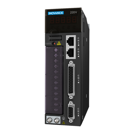
2 Wiring 2.3 Terminals of Servo Drive Figure 2-6 Terminal arrangement of IS620P DO4+ +24V CN3 and CN4 DO3- CANH DO3+ CANL GNDG DO2- RS485+ DO2+ PULLHI RS485- PAO+ RS232 DO1- HPULSE- RS232 PAO- DO1+ SIGN+ PBO- HPULSE+ PZO- (20-bit serial encoder) SIGN- PBO+ HSIGN-... -
Page 20: Main Circuit Terminals
2 Wiring 2.3.1 Main Circuit Terminals Figure 2-7 Terminal block arrangement of SIZE A (SIZE C) Table 2-1 Names and functions of main circuit terminals of SIZE A (SIZE C) Terminal Terminal Name Terminal Function Symbol Single-phase power input. L1, L2 Connect 220 VAC power supply between L1 and L2 terminals. - Page 21 2 Wiring Figure 2-8 Terminal block arrangement of SIZE E Table 2-2 Names and functions of main circuit terminals of SIZE E Terminal Terminal Name Terminal Function Symbol Main circuit power input R, S, T Main circuit three-phase 380 V power input. terminals Control power input Connect to control power input.
-
Page 22: Control Signal Terminal Connector Cn1
2 Wiring 2.3.2 Control Signal Terminal Connector CN1 Figure 2-9 Pin layout of control circuit terminal connector of servo drive DO4+ +24V DO3- DO3+ DO2- DO2+ PULLHI PAO+ DO1- HPULSE- PAO- SIGN+ DO1+ PBO- HPULSE+ PZO- SIGN- PBO+ HSIGN- DO4- PULSE+ COM+ DO5-... - Page 23 2 Wiring Signal Pin No. Function Description HSIGN+ High-speed position reference symbols HSIGN- Position reference PULLHI External power input terminal of reference pulse Signal ground AI Signals Table 2-4 AI signal description Signal Default Function Pin No. Function Description Ordinary analog input signals Resolution: 12 bit;...
-
Page 24: Communication Signal Terminal Connectors Cn3/Cn4
2 Wiring Signal Default Function Function Description DO4+ ALM+ Fault output DO4- ALM- General DO5+ HomeAttain+ Homing completed DO5- HomeAttain- Encoder Frequency-Division Output Signal Table 2-6 Encoder frequency-division output signal specifications Default Signal Pin No. Function Description Function PAO+ Phase A output signal PAO- Phases A+B quadrature pulse output signal PBO+... -
Page 25: Analog Monitoring Signal Terminal Connector Cn5
2 Wiring 2.3.4 Analog Monitoring Signal Terminal Connector CN5 The following figure shows pin layout of the analog monitoring signal terminal connector CN5. Figure 2-10 Analog monitoring signal terminal connector Definition Corresponding interface circuit: Analog output: -10 to +10 V Maximum output current: 1 mA 2.4 Cables 2.4.1 Cable Model... - Page 26 Power cable Power cable: prepared by customer ISMH3-*******-A3*** (above 2.9 kW) Absolute encoder cable S6-L-P21-3.0 S6-L-P21-5.0 S6-L-P21-10.0 The servo motor encoder cable includes CN1 connector; if you select Inovance matching Note cables, the connector kit is not required. - 25 -...
- Page 27 If you prepare cables yourself rather than use Inonvace matching cables , the connector kit is Note required. ■ Battery Kit of Absolute Encoder Motor If Inovance absolute encoder motor is used, the optional battery kit S6-C4 (battery, battery box) is required besides the matching cables. Communication Cable Cable Model Description S6-L-T00-3.0...
-
Page 28: Cable Connectors
2 Wiring 2.4.2 Cable Connectors Servo Motor Cables Table 2-8 Connectors of cables on servo motor side Frame Size Connector Appearance Pin Layout of Matching Motor Black 6-pin connector Pin No. Signal Color White Black 40 (Z series) Yellow/ 60 (Z series) Green 80 (Z series) Brake (regardless of... - Page 29 1. Frame size of motor: indicates the width of motor flange. Note 2. The motor cable colors are subject to the actual. The cable colors mentioned in the manual are all Inovance cables. - 28 -...
- Page 30 2 Wiring Encoder Cables ■ Serial Incremental Encoder Table 2-9 Connectors of 20-bit encoder cables on servo drive side Connector Appearance Pin Layout Pin No. Signal Viewed from Housing this side Recommendation: Plastic housing of plug on cable side: DB9P (SZTDK), black housing Core: DB9P soldering plug (SZTDK), blue glue Table 2-10 Connectors of 20-bit encoder cables (9-pin connector) Frame Size...
- Page 31 Signal Color Twisted-pair Yellow Twisted-pair Blue White Shielded Shielded Table 2-12 Pin connection relation of IS620P series 20-bit encoder cables Motor Side DB9 on Servo Drive Side Function Description 9-pin 20-29 Military Spec. Signal Pin No. Pin No. Pin No.
- Page 32 23AWG (0.26 mm 68.5 20.9 22AWG (0.32 mm 54.3 26.4 Note If the cables of above 22AWG are required, contact Inovance. ■ Absolute Encoder Table 2-14 Connectors of absolute encoder cables (9-pin connector) Frame Size Connector Appearance and Pin Layout of Matching...
- Page 33 2 Wiring Table 2-15 Connectors of absolute encoder cables (MIL-DTL-5015 series 3108E20-29S military spec. plug) Frame Size Connector Appearance and Pin Layout of Matching Motor Encoder connection socket Encoder cable connector Connect to CN2 of the drive 20-29 military spec. 20-29 military spec.
-
Page 34: Chapter 3 Operation And Display
3 Keypad and Display Chapter 3 Operation and Display 3.1 Introduction to Keypad Figure 3-1 Diagram of the keypad Drive model and barcode Display MODE The keypad on the servo drive consists of the 5-digit 7-segment LEDs and keys. The keypad is used for display, parameter setting, user password setting and general functions operations. -
Page 35: Display Switchover
3 Keypad and Display 3.2.1 Display Switchover Figure 3-2 Switching between different display Fault display MODE Switch to MODE MODE group H0B Status Parameter Monitoring Power-on display display display MODE MODE After you set H02-32, the keypad switches over the display automatically after motor rotation. Motor static ●... -
Page 36: User Password
3 Keypad and Display Figure 3-3 Keypad operation of parameter setting Servo status display Servo ready MODE MODE Function code group display MODE Function code No. display Parameter DOWN value display MODE Parameter setting completed ● MODE: Switch the display mode and return to the upper-level menu. ●... - Page 37 3 Keypad and Display Figure 3-4 Keypad operation of user password setting Start Power-on View value of H02-30 "SET" Last digit Display blinking? "- - - - -" "SET" Enter preset password Set password "SET" "SET" Password Display Display correct? "Error"...
-
Page 38: Chapter 4 Quick Setup
4 Quick Steup Chapter 4 Quick Setup The following part shows the quick setup flowchart. Start Para. Parameter Name Default Commissioning Model Model Check models H01-02 Servo drive SN dependent dependent Model H00-00 Motor SN 14000 dependent If position control H02-00 Control mode selection 0: Speed mode... - Page 39 4 Quick Steup Continue Para. Parameter Name Default Commissioning H06-07 Maximum speed limit 6000 If torque control H02-00 Control mode selection 0: Speed mode 1: Position mode 2: Torque mode 3: Torque mode/Speed mode 4: Speed mode/Position mode 5: Torque mode/Position mode 6: Torque mode/Speed mode/Position mode H07-00 Main torque reference A source...
- Page 40 4 Quick Steup Continue Para. Parameter Name Default Commissioning H03-09 DI4 logic selection 1: S-ON (Servo ON) H03-10 DI5 function selection H03-11 DI5 logic selection ……. ……… H03-16 DI8 function selection 31: HomeSwitch (Home switch) H03-17 DI8 logic selection H03-18 DI9 function selection 0: No function H03-19...
- Page 41 4 Quick Steup Continue Para. Parameter Name Default Commissioning Set AI1 if used as torque H03-81 Torque corresponding to 10 V reference 1.0 to 8.0 times of rated torque H03-54 AI1 zero drift H03-53 AI1 dead zone H03-51 AI1 filter time constant Set AI2 if used as torque H03-81 Torque corresponding to 10 V...
- Page 42 4 Quick Steup Continue Para. Parameter Name Default Commissioning H04-07 DO4 function selection 11: ALM (Fault output) H04-08 DO4 logic selection H04-09 DO5 function selection 16: Home Attain (Home attaining output) H04-10 DO5 logic selection Set AO1 if used H04-50 AO1 signal selection 0: Motor speed H04-51...
-
Page 43: Chapter 5 Troubleshooting
5 Troubleshooting Chapter 5 Troubleshooting 5.1 During Startup 5.1.1 Position Control During Startup Fault Symptom Cause Confirming Methods After disconnecting CN1, CN2, CN3 and CN4, 1. The control power the fault persists. voltage is abnormal. Measure AC voltage between L1C and L2C. For single-phase 220 V model, measure AC voltage between L1 and L2. - Page 44 5 Troubleshooting During Startup Fault Symptom Cause Confirming Methods High/low-speed pulse input terminal is wired incorrectly. When H05-00 = 0 (pulse is main position reference source), check whether high/low- speed pulse input terminal is wired correctly by referring to Chapter 3 in the IS620P User Manual.
-
Page 45: Speed Control
5 Troubleshooting During Startup Fault Symptom Cause Confirming Methods Motor speed is not The gain is set Perform automatic gain tuning. steady. improperly. Servo motor jitters at low Motor shaft vibrates The load inertia ratio If servo motor can run safely, perform inertia speed. - Page 46 5 Troubleshooting During Startup Fault Symptom Cause Confirming Methods The operation panel displays "Er. Remove the fault. xxx". Set operation panel to servo status display and view whether the operation panel displays "rdy" rather than "run". Check whether any parameter in groups H03 and H17 is set for FunIN1(S-ON).
- Page 47 5 Troubleshooting During Startup Fault Symptom Cause Confirming Methods 1. When AI is selected to input speed reference, check whether polarity of input signal is reverse. 2. When digital setting is used to set speed reference, check whether H06-03 (keypad setting value of speed reference) is smaller than 0.
-
Page 48: Torque Control
5 Troubleshooting 5.1.3 Torque Control During Startup Fault Symptom Cause Confirming Methods After disconnecting CN1, CN2, CN3 and CN4, the 1. The control power fault persists. voltage is abnormal. Measure AC voltage between L1C and L2C. For single-phase 220 V mode, measure AC voltage between L1 and L2. - Page 49 5 Troubleshooting During Startup Fault Symptom Cause Confirming Methods AI wiring is incorrect. When AI is selected to input torque reference, check whether polarity of input signal is reverse. Selection of torque reference is incorrect. Check whether H07-02 (torque reference source) is set correctly.
-
Page 50: During Running
(H1-01) via operating panel or drive version and the MCU technical support. Update debugging platform of Inovance. Check whether the non- software version do not matching FPGA or MCU zero numbers of the most significant bit of the versions match. - Page 51 View servo drive and servo motor nameplates Servo motor SN does not exist. If you to check that the equipment you are using is use IS620P series servo drive and 20- IS620P series servo drive and 20-bit servo bit servo motor (-U2***) of Inovance, 1.
- Page 52 1. Servo drive model and to check that the equipment you are using is again. If you use IS620P series servo servo motor model do not IS620P series servo drive and 20-bit servo drive and 20-bit servo motor (-U2***) match.
- Page 53 You can view current Adjust the gain. oscillates feedback by using the drive Inovance servo commissioning software. Check whether encoder cable you use is standard configuration of Inovance. check whether cable is aging, corrosive or is 8.
- Page 54 Replace the servo drive. times out. Internal chip is damaged. Use encoder cable that is configured as standard by Inovance. If not, check whether encoder cable comply with specification and Internal fault code H0B-45 = 2208. whether it is shielded twisted pair cable.
- Page 55 Replace matching servo drive and View servo drive and servo motor nameplates servo motor. If you use IS620P series 3. Encoder type is set to check that the equipment you are using is servo drive and 20-bit servo motor...
- Page 56 220 V drive: H0B-26 > 420 V sampling value has 380 V drive: H0B-26 > 760V a large deviation Contact Inovance for technical support. Measure the DC bus voltage between from the measured value . Check whether the DC bus voltage is normal and smaller than H0B- 7.
- Page 57 5 Troubleshooting Er.410: Main circuit undervoltage Cause Confirming Methods Corrective Action Check power input specification of servo drive. Measure RST input voltage on servo drive side and check whether input voltage 1. The main power is complies with the following specification. unstable or fails.
- Page 58 4. Motor speed Adjust the gain or adjust mechanical overspeed level through the drive debugging overshoots. condition. platform of Inovance. 5. The servo drive is The fault persists after servo drive is re-powered Replace the servo drive. faulty. - 57 -...
- Page 59 5 Troubleshooting Er.510: Pulse output overspeed Cause Confirming Methods Corrective Action When H05-38 = 0 (encoder frequency-division output), calculate pulse frequency corresponding Output pulse to motor speed at occurrence of fault and check frequency Decrease H05-17 (Encoder frequency- whether the pulse frequency exceeds limit. exceeds division pulses), making output pulse frequency upper...
- Page 60 View servo drive nameplate and 5. The servo drive or For IS620P series products, view serial encoder set servo drive model (H01-02) motor model is set motor model in H00-05 and servo drive model in correctly and replace matching incorrectly.
- Page 61 Check wirings. cable breaks. again or replace them. Check running reference and motor speed (H0B-00) by using the drive debugging platform of Inovance or operating panel. Running reference in the position control mode: H0B-13 (input reference pulse counter) 3. Motor rotor is locked...
- Page 62 Check whether there is large equipment generating interference around servo system or whether there Prefer to use the cable configured are several variable-frequency power devices inside by Inovance as standard. the cabinet. If non-standard cable is used, Make servo drive in "rdy" status and rotate motor...
- Page 63 20-bit servo motor (-U2***) and servo motor. match. of Inovance. Meanwhile, check whether H00-00 (Motor SN) is 14000. Check whether encoder cable breaks and whether Replace a new encoder cable 2. Encoder cable breaks.
- Page 64 Check running reference and motor speed (H0B-00) by using the drive debugging platform of Inovance or operating panel. Running reference in the position control mode: H0B-13 (input reference pulse 3. Motor rotor is locked...
- Page 65 Check running reference and motor speed (H0B- 00) by using the drive debugging platform of Inovance or operating panel. Running reference in the position control mode: H0B-13 (input reference pulse counter) 3. Motor rotor is locked...
- Page 66 Monitor running curve on the drive debugging If position reference is not 0, but platform of Inovance: 7. The servo drive/ position feedback is always 0, motor is faulty. Position reference, position feedback, speed replace servo drive/motor.
-
Page 67: Troubleshooting Of Warnings
5 Troubleshooting 5.2.3 Troubleshooting of Warnings Er.110: Setting error of frequency-division pulse output Cause Confirming Methods Corrective Action For incremental encoder, the number of frequency-division pulses cannot exceed encoder resolution. The number of Resolution of 20-bit serial incremental encoder is 1048576 Reset H05-17 (Encoder frequency-division P/r. - Page 68 Adjust the gain. causing too high rigidity. generates noise during running. View servo drive nameplate and For IS620P series products, view serial set servo drive model (H01-02) 5. The servo drive or motor encoder motor model in H00-05 and servo correctly and replace matching servo model is set incorrectly.
- Page 69 5 Troubleshooting Er.920: Regenerative resistor overload Cause Confirming Methods Corrective Action Replace a new external regenerative resistor and measure its resistance. Disconnect external regenerative If the resistance is consistent with resistor and measure whether 1. Wiring of external regenerative nominal value, connect it between resistance of the resistor is ∞.
- Page 70 5 Troubleshooting Cause Confirming Methods Corrective Action 10. The servo drive is faulty. Replace a new servo drive. Er.922: Resistance of external braking resistor too small Cause Confirming Methods Corrective Action If yes, connect an external regenerative When an external resistor matching servo drive between regenerative resistor is used Measure resistance of the external...
-
Page 71: Internal Faults
H0C-00 is not occurs. address) is allocated repeatedly. repeated. 5.2.4 Internal Faults When any of the following fault occurs, contact Inovance for technical support. Er.602: Angle auto-tuning failure Er.220: Phase sequence incorrect Er.A40: Motor auto-tuning failure Er.111: Servo internal parameters abnormal... -
Page 72: Chapter 6 Parameter Table
Control mode: CM; Reference unit: Ref; Enc: Enc Group H00: Servo Motor Parameters Function Parameter Name Setting Range Unit Default Pro CM Code 14000: Inovance 20-bit incremental encoder motor H00-00 Motor SN 14000 14101: Inovance 23-bit absolute encoder motor Customized firmware H00-02 version... -
Page 73: Group H01: Servo Drive Parameters
Pro CM Code Ox000: Common incremental encoder (UVW-ABZ) H00-30 Encoder selection (Hex) 0x013 0x013: Inovance 20-bit serial encoder H00-31 PPR of encoder 0 to 1073741824 1048576 Po H00-33 Electrical angle of signal Z 0.0 to 360 ° Electrical angle of phase U H00-34 0.0 to 360... - Page 74 6 Parameter Table Function Parameter Name Setting Range Unit Default ET Code 0: Coast to stop, keeping de- energized state 1: Emergency stop, keeping position H02-07 Stop mode at limit switch signal locking state 2: Emergency stop, keeping de- energized state 0: Coast to stop, keeping de- H02-08 Stop mode at NO.1 fault energized state...
-
Page 75: Group H03: Input Terminal Parameters
6 Parameter Table Function Parameter Name Setting Range Unit Default ET Code Maximum braking current at H02-39 0 to 3000 0.1% 1000 short-circuit Group H03: Input Terminal Parameters Function Parameter Name Setting Range Unit Default ET Pro CM Code 0–0xFFFF DI function (active after H03-00 Bit0: FunIN.1;... - Page 76 6 Parameter Table Function Parameter Name Setting Range Unit Default ET Pro CM Code Input polarity: 0 to 4 0: Low level valid 1: High level valid H03-13 DI6 logic selection 2: Rising edge valid 3: Falling edge valid 4: Rising edge and falling edge both valid H03-14 DI7 function selection 0 to 37 Input polarity: 0 to 4...
-
Page 77: Group H04: Output Terminal Parameters
6 Parameter Table Group H04: Output Terminal Parameters Function Parameter Name Setting Range Unit Default ET Pro CM Code H04-00 DO1 function selection 0 to 22 0: Output low level when valid (optocoupler ON) H04-01 DO1 logic selection 1: Output high level when valid (optocoupler OFF) H04-02 DO2 function selection 0 to 22 0: Output low level when valid (optocoupler ON) -
Page 78: Group H05: Position Control Parameters
6 Parameter Table Function Parameter Name Setting Range Unit Default ET Pro CM Code 00: Motor speed (1 V/1000 RPM) 01: Speed reference (1 V/1000 RPM) 02: Torque reference (1 V/1 time of rated motor torque) 03: Position deviation (0.05 V/1 reference unit) H04-53 AO2 signal selection 04: Position deviation (0.05 V/Enc) - Page 79 6 Parameter Table Function Parameter Name Setting Range Unit Default Code 0: Pulse + direction, positive logic 1: Pulse + direction, negative logic H05-15 Pulse input format 2: Phase A + phase B quadrature pulse, 4-frequency multiplication 3: CW + CCW 0: Clear position deviation when S-ON is turned off or a fault occurs 1: Clear position deviation pulses when...
- Page 80 6 Parameter Table Function Parameter Name Setting Range Unit Default Code 0: Disabled 1: Input HomingStart signal from DI to enable homing 2: Input HomingStart signal from DI to Homing enabling H05-30 enable electrical home attaining method 3: Start homing immediately upon power-on 4: Perform homing immediately 5: Start electrical home attaining 6: Take current position as the home...
- Page 81 6 Parameter Table Function Parameter Name Setting Range Unit Default Code 0: Encoder frequency-division output Servo pulse output 1: Pulse synchronous output H05-38 source 2: Frequency-division or synchronous output inhibited 0: Switchover if position reference (reference unit) = 0 and the duration Electronic gear ratio H05-39 reaches 2.5 ms...
-
Page 82: Group H06: Speed Control Parameters
6 Parameter Table Group H06: Speed Control Parameters Function Parameter Name Setting Range Unit Default ET Code 0: Digital setting (H06-03) Main speed reference A H06-00 1: AI1 source 2: AI2 0: Digital setting (H06-03) 1: AI1 2: AI2 Auxiliary speed reference B H06-01 source 3: 0 (invalid) - Page 83 6 Parameter Table Function Parameter Name Setting Range Unit Default ET Pro CM Code 0: Digital setting (H07-03) Auxiliary torque reference B H07-01 1: AI1 source 2: AI2 0: Main torque reference A source 1: Auxiliary torque reference B source H07-02 Torque reference source 2: A + B 3: A/B switchover...
-
Page 84: Group H08: Gain Parameters
6 Parameter Table Group H08: Gain Parameters Function Parameter Name Setting Range Unit Default ET Pro CM Code H08-00 Speed loop gain 0.1 to 2000.0 25.0 Time constant of speed loop H08-01 0.15 to 512.00 31.83 integration H08-02 Position loop gain 0.0 to 2000.0 40.0 H08-03 2nd gain of speed loop... -
Page 85: Group H09: Automatic Gain Tuning Parameters
6 Parameter Table Function Parameter Name Setting Range Unit Default ET Pro CM Code Cutoff frequency of speed H08-23 100 to 4000 4000 feedback low-pass filter H08-24 PDFF control coefficient 0.0 to 100.0 100.0 *: Based on switchover condition Group H09: Automatic Gain Tuning Parameters Function Parameter Name Setting Range... -
Page 86: Group H0A: Fault And Protection Parameters
6 Parameter Table Function Parameter Name Setting Range Unit Default Pro CM Code H09-12 1st notch frequency 50 to 4000 4000 H09-13 1st notch width level 0 to 20 H09-14 1st notch depth level 0 to 99 H09-15 2nd notch frequency 50 to 4000 4000 H09-16... -
Page 87: Group H0B: Monitoring Parameters
6 Parameter Table Function Parameter Name Setting Range Unit Default Code 0: Encoder unit H0A-17 Position setting unit 1: Reference unit H0A-19 DI8 filter time constant 0 to 255 25 ns H0A-20 DI9 filter time constant 0 to 255 25 ns Filter time constant of low- H0A-24 0 to 255... - Page 88 6 Parameter Table Function Parameter Name Setting Range Unit Default Code H0B-07 Absolute position counter H0B-09 Mechanical angle H0B-10 Electric angle ° H0B-11 Speed corresponding to input position reference H0B-12 Average load ratio H0B-13 Input position reference counter H0B-15 Encoder position deviation counter H0B-17 Feedback pulse counter H0B-19 Total power-on time H0B-21 AI1 sampling voltage...
-
Page 89: Group H0C: Communication Parameters
6 Parameter Table Function Parameter Name Setting Range Unit Default Code H0B-85 Rotating load single-turn position Group H0C: Communication Parameters Function Parameter Name Setting Range Unit Default Code 0: Broadcast address H0C-00 Servo axis address 1 to 247 0: 2400 Kbps; 1: 4800 Kbps H0C-02 Serial baud rate 2: 9600 Kbps;... -
Page 90: Group H0D: Auxiliary Function Parameters
6 Parameter Table Function Parameter Name Setting Range Unit Default Code Modbus error frame H0C-30 0: Old protocol; 1: New protocol (standard) format Group H0D: Auxiliary Function Parameters Function Parameter Name Setting Range Unit Default ET Pro CM Code H0D-00 Software reset 0: Disabled;... -
Page 91: Group H11: Multi-Position Function Parameters
6 Parameter Table Function Parameter Name Setting Range Unit Default ET Pro Code Filter time constant of hybrid H0F-13 0 to 6553.5 vibration suppression Full closed-loop position H0F-16 -1073741824 to 1073741824 Ext enc deviation counter Feedback pulse counter of H0F-18 -1073741824 to 1073741824 Int enc internal encoder... - Page 92 6 Parameter Table Function Parameter Name Setting Range Unit Default Code Acceleration/Deceleration time of H11-25 0 to 65535 ms (s) 3rd displacement H11-26 Waiting time after 3rddisplacement 0 to 10000 ms (s) -1073741824 to H11-27 4th displacement 10000 1073741824 Maximum running speed of 4th H11-29 1 to 6000 displacement...
- Page 93 6 Parameter Table Function Parameter Name Setting Range Unit Default Code -1073741824 to H11-57 10th displacement 10000 1073741824 Maximum running speed of 10th H11-59 1 to 6000 displacement Acceleration/Deceleration time of H11-60 0 to 65535 ms (s) 10th displacement H11-61 Waiting time after 10th displacement 0 to 10000 ms (s) -1073741824 to H11-62 11th displacement...
-
Page 94: Group H12: Multi-Speed Function Parameters
6 Parameter Table Function Parameter Name Setting Range Unit Default Code Acceleration/Deceleration time of H11-90 0 to 65535 ms (s) 16th displacement H11-91 Waiting time after 16th displacement 0 to 10000 ms (s) Group H12: Multi-Speed Function Parameters Function Parameter Name Setting Range Unit Default ET Code... - Page 95 6 Parameter Table Function Parameter Name Setting Range Unit Default ET Code Running time of 4th speed H12-30 0 to 6553.5 reference (min) 0: No acceleration/deceleration time 1: Acceleration/Deceleration time 1 Acceleration/deceleration time H12-31 2: Acceleration/Deceleration time 2 of 4th speed reference 3: Acceleration/Deceleration time 3 4: Acceleration/Deceleration time 4 H12-32...
- Page 96 6 Parameter Table Function Parameter Name Setting Range Unit Default ET Code 0: No acceleration/deceleration time 1: Acceleration/Deceleration time 1 Acceleration/deceleration time H12-49 2: Acceleration/Deceleration time 2 of 10th speed reference 3: Acceleration/Deceleration time 3 4: Acceleration/Deceleration time 4 H12-50 11th speed reference -6000 to 6000 -300...
-
Page 97: Group H17: Vdi/Vdo Parameters
6 Parameter Table Function Parameter Name Setting Range Unit Default ET Code 0: No acceleration/deceleration time 1: Acceleration/Deceleration time 1 Acceleration/deceleration time H12-67 2: Acceleration/Deceleration time 2 of 16th speed reference 3: Acceleration/Deceleration time 3 4: Acceleration/Deceleration time 4 Group H17: VDI/VDO Parameters Function Parameter Name Setting Range... - Page 98 6 Parameter Table Function Parameter Name Setting Range Unit Default ET Pro CM Code 0: Valid when logic is 1 H17-23 VDI12 logic selection 1: Valid when logic changes from 0 to 1 H17-24 VDI13 function selection 0 to 37 0: Valid when logic is 1 H17-25 VDI13 logic selection 1: Valid when logic changes from 0 to 1...
-
Page 99: Group H30: Servo Variables Read Via Communication
6 Parameter Table Function Parameter Name Setting Range Unit Default ET Pro CM Code H17-53 VDO11 function selection 0 to 22 0: Output 1 when function valid H17-54 VDO11 logic selection 1: Output 0 when function valid H17-55 VDO12 function selection 0 to 22 0: Output 1 when function valid H17-56 VDO12 logic selection... -
Page 100: Di/Do Function Definitions
6 Parameter Table DI/DO Function Definitions Function Function Name Description Remarks Symbol Input Function Description The logic of the corresponding terminal needs to be set to level valid. Invalid: Servo motor disabled FunIN.1 S-ON Servo ON The change of the Valid: Servo motor enabled corresponding DI or VDI or terminal logic takes effect only... - Page 101 6 Parameter Table Function Function Name Description Remarks Symbol It is recommended that the Multi-reference Used to select one from the 16 FunIN.7 CMD2 logic of the corresponding switchover 2 references terminal be set to level valid. It is recommended that the Multi-reference Used to select one from the 16 FunIN.8...
- Page 102 6 Parameter Table Function Function Name Description Remarks Symbol The torque limit source is switched over based on the setting of H07-07. H07-07 = 1: Valid: External positive torque limit enabled Invalid: Internal positive torque limit enabled External It is recommended that the H07-07 = 3 and AI limit larger FunIN.16 P-CL...
- Page 103 6 Parameter Table Function Function Name Description Remarks Symbol HX1 valid, HX2 invalid: X10 Handwheel It is recommended that the FunIN.21 multiplying HX1 invalid, HX2 valid: X100 logic of the corresponding factor signal 1 terminal be set to level valid. Other: X1 Handwheel FunIN.22...
- Page 104 6 Parameter Table Function Function Name Description Remarks Symbol The logic of the corresponding terminal needs to be set to level valid. Allocate this function to the high-speed DI terminal. If the logic is set to 2 (rising edge valid), the servo drive Invalid: Not triggered forcibly changes it to 1 (high level valid).
- Page 105 6 Parameter Table Function Function Name Description Remarks Symbol When the position reference source is pulse input (H05- 00 = 0) in the position control It is recommended that the Pulse input mode: FunIN.37 PulseInhibit logic of the corresponding inhibited Invalid: Respond to pulse input terminal be set to level valid.
- Page 106 6 Parameter Table Function Function Name Description Remarks Symbol Confirming speed limit in torque control: Invalid: Motor speed not reaching the speed limit FunOUT.8 V-LT Speed limit Valid: Motor speed reaching the speed limit and speed loop built internally based on the speed limit Brake output: Invalid: The power is on, the...
- Page 107 6 Parameter Table Function Function Name Description Remarks Symbol Valid: Angle auto-tuning com- pleted Angle auto- FunOUT.20 AngIntRdy tuning output Invalid: Angle auto-tuning not completed Valid: Dynamic braking relay open DB braking FunOUT.21 output Invalid: Dynamic braking relay close Valid: Internal reference com- Internal pleted FunOUT.22...
- Page 108 Revision History Date Version Change Description March 2016 First issue. Dec 2016 Modified product name, designation rule and nameplate.
Need help?
Do you have a question about the IS620P Series and is the answer not in the manual?
Questions and answers