Sign In
Upload
Manuals
Brands
Inovance Manuals
Servo Drives
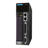
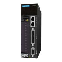
IS620PT3R5I
Inovance IS620PT3R5I Manuals
Manuals and User Guides for Inovance IS620PT3R5I. We have
2
Inovance IS620PT3R5I manuals available for free PDF download: User Manual, Manual
Inovance IS620PT3R5I User Manual (223 pages)
Brand:
Inovance
| Category:
Servo Drives
| Size: 6 MB
Table of Contents
Preface
2
Product Checking
3
Table of Contents
4
Servo System Selection
6
Chapter 1 Servo System Selection
7
Servo Drive Composition
7
Wiring Example of Three-Phase 220 V System
8
Designation Rules of the Servo Motor and Servo Drive
9
220 V
10
Designation Rules of the Servo Drive
10
Servo System Configuration
10
380 V
11
Adapted Cables
11
Adapted Cables for Servo Motor Without Brake
11
Adapted Cables for Servo Motor with Brake
12
Communication Cables
13
Physical Appearance of Cables for the Servo Motor and Servo Drive
14
Regen Resistor Specifications
16
Mounting Dimensions
18
Chapter 2 Mounting Dimensions of Servo System
19
Installation Environment
19
Installation Location
19
Installation of the Servo Motor
19
Installation Precautions
20
Installation of the Servo Drive
21
Installation Diagram of the Servo Drive
22
Cooling
23
Installation Side by Side
23
Mounting Dimensions of the ISMH1 Series Z Motor
23
Mounting Dimensions of the Servo Motor
23
Overall Dimensions of the ISMH1 Series X Motor
26
200 W, 400 W (Vn = 3000 Rpm, Vmax = 6000 Rpm)
27
750 W (Vn = 3000 Rpm, Vmax = 6000 Rpm)
28
Overall Dimensions of the ISMH2 Series Servo Motor
29
3.0 Kw, 4.0 Kw, 5.0 Kw
30
850 W, 1.3 Kw, 1.8 Kw
31
2.9 Kw, 4.4 Kw, 5.5 Kw, 7.5 Kw
32
400 W
33
750 W
34
Overall Dimensions of the Servo Drive
37
Wiring of Servo System
38
Chapter 3 Wiring of Servo System
39
Terminal Pin Arrangement of the Servo Drive
39
Introduction to the Main Circuit
40
Names and Functions of Main Circuit Terminals
40
Servo Drive Main Circuit Wiring
40
Servo Drive Main Circuit Wiring Example
40
Dimension Drawing of the Servo Drive Terminal Block
42
Rated Input and Output Currents of IS620P Series Servo Drive
42
Recommended Models and Specifications of Main Circuit Cables
42
Recommended Main Circuit Cable Sizes of IS620P Series Servo Drive
43
Recommended Main Circuit Lugs of IS620P Series Servo Drive
43
Sizes and Appearance of Lugs
44
Main Circuit Wiring of Single-Phase 220 V Servo Drive
45
Main Circuit Wiring of Three-Phase 220/380 V Servo Drive
45
Power Supply Wiring Example
45
Connecting Servo Drive Output and Servo Motor
47
Connectors of Power Cables on Servo Motor Side
47
Example of Connecting Servo Drive Output and Servo Motor
47
Connecting Servo Motor Encoder Signals
49
Connectors of Encoder Cables at Servo Motor Side
49
Connectors of Encoder Cables on Servo Drive Side
49
Example of Connecting Encoder Signals
49
Pin Connection Relation of Encoder Cables
50
Recommended Cable Sizes
50
Connecting Control Signal Terminals
51
Pin Layout of Control Circuit Terminal Connectors of Servo Drive
51
Wiring Examples in Speed/Position/Torque Control Mode
52
DI Circuit
53
DI/DO Signal Description
53
DI/DO Signals
53
DO Circuit
54
When Input Signal of the Upper Device Is Relay Input
54
When Output Signal of the Upper Device Is OC Output
54
AI Signal Description
55
AI Signals
55
When Input Signal of the Upper Device Is Optocoupler Input
55
Common Reference Pulse Input
56
Correspondence between Maximum Input Frequency and Minimum Pulse Width
56
Position Reference Input Signals
56
Position Reference Signal Description
56
OC Mode
57
When the Internal 24 V Power Supply of the Servo Drive Is Used
57
Wrong Connection
57
Recommended R1 Resistance
58
Using Internal Resistor of the Servo Drive
58
High-Speed Reference Pulse Input
60
Encoder Frequency Dividing Output Circuit
61
2-Pin Plug, Regardless of Positive or Negative Polarity
62
Models of Holding Brake Connectors for Frame 40/60/80 Servo Motor
62
Wiring of Holding Brake
62
Brake Specifications
63
Wiring Example of Holding Brake
63
Wiring Precautions
63
Servo Motor Running When Servo Drive Is off
64
Servo Motor Stopping When Servo Drive Is off
64
Communication Signal Terminal Pin Definition
65
Communication Signal Wiring
65
Communication Cable Appearance
66
Definition of DB9 Terminal Pins at PC Side
66
Pin Definition of the Communication Cable
66
Serial-To-USB Conversion Diagram
66
Appearance of the Communication Cable between PLC and Servo Drive
67
Pin Definition of Communication Cable between the PLC and Servo Drive
67
Pin Definition of the Communication Cable for Parallel Connection
67
Analog Monitoring Signal Wiring
68
Corresponding Interface Circuit
68
Monitored Objects of Analog Signals
68
Anti-Interference Measures for Electrical Wiring
69
Anti-Interference Wiring Example and Grounding
69
Anti-Interference Wiring Example
70
Grounding
70
Grounding the Motor Housing
70
Grounding the Shield of the Power Cable
70
EMI Filter Grounding Cable and Output Line Wiring
71
EMI Filter Input and Output Line Wiring
71
Using EMI Filters
71
EMI Filter Grounding
72
Grounding to One Point
72
Cable Towline
73
If Cable Towline Is Used
73
Precautions of Using Cables
73
Running and Commissioning
74
Chapter 4 Running and Commissioning
75
Diagram of the Position Control Mode
76
Use of the Position Control Mode
76
Wiring of the Position Control Mode
77
Function Code Setting of the Position Control Mode
78
Position Reference Direction Setting
78
Position Reference Source
78
Pulse Reference Input Terminal Selection
78
Electronic Gear Ratio
79
Position Reference Forbidden
79
Principles of Reference Pulse Forms
79
Reference Pulse Form
79
Working Principle of the Electronic Gear Ratio
80
Position Reference Filter
81
Clearing Position Deviation
82
Frequency-Division Output
82
Output Phase Pattern
83
Diagram of the Speed Control Mode
84
Use of the Speed Control Mode
84
Wiring of the Speed Control Mode
85
Function Code Setting of the Speed Control Mode
86
Speed Reference Input Setting
86
After-Offset AI2
87
Analog Setting of Speed Reference
87
No-Offset AI2
87
Speed Reference Direction Switchover
88
Speed Reference Selection
88
Acceleration/Deceleration Time Diagram
89
Ramp Control Diagram
89
Reference Ramp Parameter Setting
89
Speed Reference Limit
90
Zero Clamp Function
91
Diagram of the Torque Control Mode
92
Use of the Torque Control Mode
92
Wiring of the Torque Control Mode
93
Function Code Setting of the Torque Control Mode
94
Torque Reference Input Setting
94
Torque Reference Source
94
Analog Setting of Torque Reference
95
Torque Reference Direction Switchover
95
Torque Reference Selection
95
No-Offset AI1
96
Speed Limit in Torque Control
96
Speed Limit Diagram
97
Torque Reference Limit
98
Check before Running
100
General Commissioning Flowchart
101
Load Inertia Auto-Tuning and Gain Adjustment
101
Inertia Auto-Tuning
102
Inertia Auto-Tuning Flowchart
102
Automatic Gain Adjustment
103
Manual Gain Adjustment
104
Notch
105
Background Software
108
Chapter 5 Background Software
109
Troubleshooting
110
Chapter 6 Troubleshooting
111
During Startup
111
Position Control
111
Positioning Control Schematic Diagram
114
When Positioning Is Inaccurate
114
If Inaccurate Positioning Occurs
115
To Remove the Cause a
115
To Remove the Cause B
115
To Remove the Cause C
115
Speed Control
116
During Running
121
Fault and Alarm Code List
121
Fault and Alarm Grading
121
Related Function Parameter
121
Fault and Alarm Records
122
Fault/Alarm DO Output
122
No.1 Non-Resettable Fault
123
No.1 Resettable Fault
124
No.2 Resettable Fault
124
No.2 Resettable Alarm
125
Er.101: Groups H02 and above Parameters Abnormal
126
Er.102: Programmable Logic Configuration Fault
127
Er.104: Programmable Logic Interruption Fault
127
Er.105: Internal Program Abnormal
128
Er.108: Parameter Storage Fault
128
Er.120: Product Model Matching Fault
128
Er.121: Invalid Servo on Command
129
Er.130: Different Dis Allocated with the same Function
129
Er.131: Number of DO Functions Exceeding the Limit
129
Er.136: Data Check Error or no Parameter Stored in the Motor ROM
130
Er.201: Overcurrent 2
131
Er.207: Shaft D/Q Current Overflow
132
Er.208: FPGA System Sampling Operation Timeout
133
Er.210: Output-To-Ground Short-Circuit
133
Er.234: Runaway
134
Er.400: Main Circuit Overvoltage
135
Er.410: Main Circuit Undervoltage
137
Er.420: Power Cable Phase Loss
138
Er.430: Control Power Undervoltage
139
Er.500: Servo Motor Overspeed
139
Er.510: Pulse Output Overspeed
141
Er.610: Servo Drive Overload
141
Er.620: Motor Overload
142
Er.630: Overheat Protection of Locked-Rotor Motor
143
Er.650: Heatsink Overheat
144
Er.740: Encoder Interference
144
Er.834: AD Sampling Overvoltage
146
Er.835: High-Accuracy AD Sampling Fault
146
Er.a33: Encoder Data Abnormal
146
Er.a34: Encoder Communication Check Abnormal
147
Er.a35: Z Signal Lost
147
Er.b00: Position Feedback Error too Large
148
Er.b01: Pulse Input Abnormal
149
Er.d03: CAN Communication Interrupted
150
Er.110: Setting Error of Frequency-Division Pulse Output
151
Troubleshooting of Alarms
151
Er.601: Home Return Timeout
152
Er.831: Excessive AI Zero Drift
153
Er.900: DI Emergency Braking
153
Er.909: Motor Overload
153
Er.920: Regen Resistor Overload
155
Er.922: the External Regen Resistor too Small
156
Er.939: Motor Power Cable Breaking
157
Er.941: Parameter Modification Taking Effect Only after Re-Power-On
157
Er.942: Parameter Storage too Frequent
157
Er.950: Forward Overtravel
158
Er.952: Reverse Overtravel
158
Er.980: Encoder Internal Fault
158
Er.990: Power Input Phase Loss
159
Er.994: CAN Address Conflict
159
Internal Faults
159
Function Code Table
160
Chapter 7 Function Code Table
161
Group H00: Servo Motor Parameters
162
Group H01: Servo Drive Parameters
162
Group H02: Basic Control Parameters
163
Group H03: Input Terminal Parameters
166
Group H04: Output Terminal Parameters
169
Group H05: Position Control Parameters
171
Group H06: Speed Control Parameters
176
Group H07: Torque Control Parameters
178
Group H08: Gain Parameters
180
Group H09: Self-Adjusting Parameters
182
Group H0A: Fault and Protection
185
Group H0B: Display Parameters
187
Group H0C: Communication Parameters
189
Group H0D: Auxiliary Function Parameters
191
Group H0F: Full Closed-Loop Parameters
192
Group H11: Multi-Position Function Parameters
193
Group H12: Multi-Speed Function Parameters
198
Group H17: VDI/VDO Parameters
204
Group H30: Servo Related Variables Read Via Communication
209
Group H31: Servo Related Variables Set Via Communication
209
DI/DO Basic Function Table
210
DI/DO Basic Functions
210
Appendix: Version Change Record
218
Advertisement
Inovance IS620PT3R5I Manual (109 pages)
AС Servo Drive and Motor Pulse & Analog Reference 20 bit Incremental Encoder
Brand:
Inovance
| Category:
Controller
| Size: 9 MB
Table of Contents
Table of Contents
2
Safety Information and Precautions
4
Chapter 1 Product Information
6
Servo Drive
6
Designation Rules and Nameplate
6
Specifications of Servo Drive
6
Specifications of Regenerative Resistor
7
Servo Motor
8
Designation Rules and Nameplate
8
Specifications of Servo Motor
9
Physical Appearance and Mounting Dimensions of Servo Drive
11
Environment
12
Chapter 2 Wiring
13
Servo System Wiring
13
Wiring in Different Modes
15
Terminals of Servo Drive
19
Main Circuit Terminals
20
Control Signal Terminal Connector CN1
22
Communication Signal Terminal Connectors CN3/CN4
24
Analog Monitoring Signal Terminal Connector CN5
25
Cables
25
Cable Model
25
Cable Connectors
28
Chapter 3 Operation and Display
34
Introduction to Keypad
34
Keypad Display
34
Display Switchover
35
Parameter Setting
35
User Password
36
Chapter 4 Quick Setup
38
Chapter 5 Troubleshooting
43
During Startup
43
Position Control
43
Speed Control
45
Torque Control
48
During Running
50
Troubleshooting of Faults
50
Troubleshooting of Warnings
67
Internal Faults
71
Chapter 6 Parameter Table
72
Group H00: Servo Motor Parameters
72
Group H01: Servo Drive Parameters
73
Group H02: Basic Control Parameters
73
Group H03: Input Terminal Parameters
75
Group H04: Output Terminal Parameters
77
Group H05: Position Control Parameters
78
Group H06: Speed Control Parameters
82
Group H07: Torque Control Parameters
82
Group H08: Gain Parameters
84
Group H09: Automatic Gain Tuning Parameters
85
Group H0A: Fault and Protection Parameters
86
Group H0B: Monitoring Parameters
87
Group H0C: Communication Parameters
89
Group H0D: Auxiliary Function Parameters
90
Group H0F: Fully Closed-Loop Parameters
90
Group H11: Multi-Position Function Parameters
91
Group H12: Multi-Speed Function Parameters
94
Group H17: VDI/VDO Parameters
97
Group H30: Servo Variables Read Via Communication
99
Group H31: Servo Variables Set Via Communication
99
DI/DO Function Definitions
100
Advertisement
Related Products
Inovance IS620PT5R4I
Inovance IS620PT012I
Inovance IS620PT021I
Inovance IS620PT026I
Inovance IS620PT5R4I-CO-INT
Inovance IS620PT8R4I-INT
Inovance IS620PT8R4I-CO-INT
Inovance IS620PT012I-INT
Inovance IS620PT017I-INT
Inovance IS620PT021I-CO-INT
Inovance Categories
DC Drives
Servo Drives
Controller
Control Unit
Inverter
More Inovance Manuals
Login
Sign In
OR
Sign in with Facebook
Sign in with Google
Upload manual
Upload from disk
Upload from URL