Sign In
Upload
Download
Table of Contents
Contents
Add to my manuals
Delete from my manuals
Share
URL of this page:
HTML Link:
Bookmark this page
Add
Manual will be automatically added to "My Manuals"
Print this page
×
Bookmark added
×
Added to my manuals
Manuals
Brands
Inovance Manuals
Servo Drives
IS650P Series
User manual
Inovance IS650P Series User Manual
Ac servo drive and motor pulse & analog reference 20-bit incremental encoder
Hide thumbs
1
Table Of Contents
2
3
4
5
6
7
8
9
10
11
12
13
14
15
16
17
18
19
20
21
22
23
24
25
26
27
28
29
30
31
32
33
34
35
36
37
38
39
40
41
42
43
44
45
46
47
48
49
50
51
52
53
54
55
56
57
58
59
60
61
62
63
64
65
66
67
68
69
70
71
72
73
74
75
76
77
78
79
80
81
82
83
84
85
86
87
88
89
90
91
92
93
94
95
96
97
98
99
100
101
102
page
of
102
Go
/
102
Contents
Table of Contents
Troubleshooting
Bookmarks
Table of Contents
Table of Contents
Safety Information and Precautions
Chapter 1 Product Information
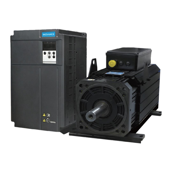
Servo Drive
Designation Rules and Nameplate
Servo Motor
Designation Rules and Nameplate
Servo System Configuration
Specifications of Regenerative Resistor
Motor Dimensions
Physical Appearance and Mounting Dimensions of Servo Drive
Chapter 2 Wiring
Servo System Wiring
Wiring in Different Modes
Terminals of Servo Drive
Main Circuit Terminals
Control Signal Terminal Connector CN1
Communication Signal Terminal Connectors CN3/CN4
Analog Monitoring Signal Terminal Connector CN5
Cables and Options
Cable Model
Cable Connectors
Chapter 3 Operation and Display
Introduction to Keypad
Keypad Display
Display Switchover
Parameter Setting
User Password
Chapter 4 Quick Setup
Chapter 5 Troubleshooting
During Startup
Position Control
Speed Control
Torque Control
During Running
Troubleshooting of Faults
Troubleshooting of Warnings
Internal Faults
Chapter 6 Parameter Table
Group H00: Servo Motor Parameters
Group H01: Servo Drive Parameters
Group H02: Basic Control Parameters
Group H03: Input Terminal Parameters
Group H04: Output Terminal Parameters
Group H05: Position Control Parameters
Group H06: Speed Control Parameters
Group H07: Torque Control Parameters
Group H08: Gain Parameters
Group H09: Automatic Gain Tuning Parameters
Group H0A: Fault and Protection Parameters
Group H0B: Monitoring Parameters
Group H0C: Communication Parameters
Group H0D: Auxiliary Function Parameters
Group H0F: Full Closed-Loop Parameters
Group H11: Multi-Position Function Parameters
Group H12: Multi-Speed Function Parameters
Group H17: VDI/VDO Parameters
Group H30: Servo Variables Read by Communication
Group H31: Servo Variables Set Via Communication
DI/DO Function Definitions
Revision History
Advertisement
Quick Links
1
Servo Drive
2
Servo Motor
3
Troubleshooting of Faults
Download this manual
Table of
Contents
Previous
Page
Next
Page
1
2
3
4
5
Advertisement
Table of Contents
Troubleshooting
Chapter 5 Troubleshooting
34
During Running
42
Troubleshooting of Warnings
59
Need help?
Do you have a question about the IS650P Series and is the answer not in the manual?
Ask a question
Questions and answers
Related Manuals for Inovance IS650P Series
Servo Drives Inovance IS580 Series User Manual
(151 pages)
Servo Drives Inovance IS580 Series User Manual
Hydraulic servo drive. closed loop pressure and flow control (68 pages)
Servo Drives Inovance IS300 Series User Manual
(120 pages)
Servo Drives Inovance IS300 Series Troubleshooting Instructions
(39 pages)
Servo Drives Inovance IS300S002-C User Manual
(211 pages)
Servo Drives Inovance IS 300 Series User Manual
(100 pages)
Servo Drives Inovance IS300 Series Manual
(65 pages)
Servo Drives Inovance ISMG Series User Manual
Ac servo drive and motor pulse & analog reference 20-bit incremental encoder (102 pages)
Servo Drives Inovance IS620P Series User Manual
(223 pages)
Servo Drives Inovance IS620P Series User Manual
(184 pages)
Servo Drives Inovance IS620P Series Application Manual
Servo drive canopen communication (221 pages)
Servo Drives Inovance IS810N-INT Series User Manual
Servo system (290 pages)
Servo Drives Inovance IS810N-INT Series User Manual
Standard servo drive (576 pages)
Servo Drives Inovance SV820N Series Manual
(181 pages)
Servo Drives Inovance SV630P Series User Manual
(710 pages)
Servo Drives Inovance SV660N Series Advanced User's Manual
(426 pages)
This manual is also suitable for:
Ismg series
Is650pt025iux series
Is650pt032iux series
Is650pt037iux series
Is650pt045iux series
Is650pt060iux series
...
Show all
Is650pt075iux series
Is650pt091iux series
Is650pt112iux series
Ismg1-95c15cd-u fa series
Ismg1-95c15cd-a3 fa series
Ismg1-12d20cd-u fa series
Ismg1-12d20cd-a3 fa series
Ismg1-14d15cd-u fa series
Ismg1-14d15cd-a3 fa series
Ismg1-17d15cd-u fa series
Ismg1-17d15cd-a3 fa series
Ismg1-22d15cd-u fa series
Ismg1-22d15cd-a3 fa series
Ismg1-30d15cd-u fa series
Ismg1-30d15cd-a3 fa series
Ismg2-42d20cd-u fa series
Ismg2-42d20cd-a3 f series
Ismg2-57d20cd-u fa series
Ismg2-57d20cd-a3 f series
Is650pt025iuxa
Ismg1-30d15cd-u231fa
Is650pt025iux-b
Is650pt032iux-b
Table of Contents
Save PDF
Print
Rename the bookmark
Delete bookmark?
Delete from my manuals?
Login
Sign In
OR
Sign in with Facebook
Sign in with Google
Upload manual
Upload from disk
Upload from URL


Need help?
Do you have a question about the IS650P Series and is the answer not in the manual?
Questions and answers