Inovance IS300 Series Manual
Hide thumbs
Also See for IS300 Series:
- User manual (120 pages) ,
- Troubleshooting instructions (39 pages) ,
- User manual (211 pages)
Table of Contents
Advertisement
IS300 series servo drive is a servo drive which is specially designed for drive
permanent magnet synchronous servo motor (PMSM). IS300 series servo
drive has a wide capacity range the rated current is 5A to 300A .It's able to
provide not only servo pump control, but also the general functional
requirements. And it is a high-power servo drive which is value-for-money in
the present market.
This manual is a guide to the operations of IS300 series servo drive.
This manual provides the user with related precautions and instructions for the
prototyping, installation, parameter setup, and on-site trial run, and routine
repair and maintenance of servo drive. In order to use this series of drive
correctly, please read this manual carefully prior to operation and keep it
properly for future using. The supporting equipment customers shall distribute
this manual together with the equipment to the final users.
Unpacking and inspection:
Please confirm carefully when unpacking the box:
1)
If the model and drive rated values on the nameplate are the same as
your order. The box contains the equipment, certificate of conformity,
user manual and warranty card.
2)
If the product is damaged during the transportation. If there is any
omission or damage, please contact our company or the supplier
immediately.
First time use:
The users who use this product for the first time shall read this manual carefully.
For any doubt on certain functions and performances, please contact the
technical support personnel of our company for help so as to use this product
properly.
With commitment to the constant improvement of the servo drive, our company
may change the information provided without additional notice.
Foreword
efesotomasyon.com
Advertisement
Table of Contents

Subscribe to Our Youtube Channel
Related Manuals for Inovance IS300 Series


Summary of Contents for Inovance IS300 Series
- Page 1 Foreword IS300 series servo drive is a servo drive which is specially designed for drive permanent magnet synchronous servo motor (PMSM). IS300 series servo drive has a wide capacity range the rated current is 5A to 300A .It’s able to provide not only servo pump control, but also the general functional requirements.
- Page 2 IS300 series servo drive complies with the following international standards, and some products have passed the CE certification. IEC/EN61800-5-1:2003 “Safety Regulations on Commissionable Electric Drive System” and IEC/EN 61800-3:2004 Commissionable Electric Drive System: The third Part: Electromagnetic Compatibility Standard and Specific Testing Method for the Product.
-
Page 3: Table Of Contents
Contents FOREWORD ....................- 1 - CHAPTER 1 PRODUCT INFORMATION............- 5 - 1.1 IS300 Servo Drive Designation Rules............- 5 - 1.2 IS300 Servo Drive Series ..............- 6 - 1.3 IS300 Servo Drive Brake Components Prototyping Table .....- 7 - 1.4 IS300 Servo Drive External Electrical Parts Table.........- 8 - 1.5 Physical Appearance and Dimensions of Mounting Hole ......- 9 - CHAPTER 2 WIRING ................- 12 - 2.1 Connection Mode.................- 12 -... -
Page 4: Chapter 1 Product Information
Product Information efesotomasyon.com... -
Page 5: Is300 Servo Drive Designation Rules
Chapter 1 Product Information 1.1 IS300 Servo Drive Designation Rules efesotomasyon.com... -
Page 6: Is300 Servo Drive Series
1.2 IS300 Servo Drive Series System Maximum pressure flow rate of Power Input Output adaptable Servo drive Input supply adaptable current current injection model voltage capacity injection moulding (kVA) moulding machine Machine L/min IS300T005 10.5 IS300T010 14.6 13.0 IS300T015 11.0 20.5 17.0 IS300T020... -
Page 7: Is300 Servo Drive Brake Components Prototyping Table
1.3 IS300 Servo Drive Brake Components Prototyping Table Servo Recommended Recommended drive resistance Braking rower of brake Remarks model value of brake unit resistor resistor IS300T005 300W IS300T010 400W IS300T015 500W IS300T020 800W Built-in as No special IS300T030 1000W standard specification IS300T035 1300W... -
Page 8: Is300 Servo Drive External Electrical Parts Table
1.4 IS300 Servo Drive External Electrical Parts Table Recom- Recom- Circuit Recommen Recom- Recommend- mended mended breaker mended ed conducting conducting conducting (MCCB) contactor input Wire of main wire of wire of Servo drive filter A circuit at the main control model input side... -
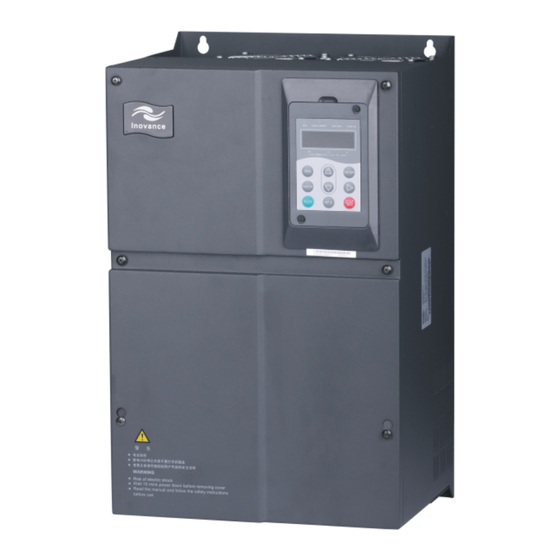
Page 9: Physical Appearance And Dimensions Of Mounting Hole
1.5 Physical Appearance and Dimensions of Mounting Hole Schematic Diagram for Physical Dimensions and Mounting Hole Dimensions of IS300T005 IS300T030 Schematic Diagram for Physical Dimensions and Mounting Hole Dimensions of IS300T005 IS300T030 efesotomasyon.com... - Page 10 Mounting Diameter of Physical dimensions Weight hole Model mounting (kg) hole IS300T005 IS300T010 IS300T015 IS300T020 IS300T030 IS300T035 IS300T040 IS300T050 IS300T070 IS300T080 IS300T100 IS300T140 IS300T170 IS300T210 IS300T250 IS300T300 efesotomasyon.com...
-
Page 11: Chapter 2 Wiring
Wiring efesotomasyon.com... -
Page 12: Connection Mode
Chapter 2 Wiring 2.1 Connection Mode efesotomasyon.com... -
Page 13: Main Circuit Terminals And Connections
2.2 Main Circuit Terminals and Connections Terminals Name Description Input terminal of R S T R three-phase AC single-phase 220V power connection point S and T power supply Negative Shared DC bus input point (connection point of (-)(+) and positive external braking unit of above IS300T070 and (-) terminals of... -
Page 14: Control Terminals And Connections
2.3 Control Terminals and Connections Type Terminal Terminal name Function description Provide 10V±10% power supply for external-units, and the maximum output current is 10mA. +10V-GND 10V power supply It is generally used as the operating power supply for the external potentiometer. The potentiometer resistance range is 1 k to 5k . - Page 15 Type Terminal Terminal name Function description Analog input 1 The resolution is 12 bit, the correction terminal 2 AI2-GND precision is 0.5 %. default flow Input resistance 100k setting 1. Input range: ±10V/0 to 20mA, which is determined by J5 jumper on the control Analog input board.
- Page 16 Type Terminal Terminal name Function description voltage current output determined by the J4 jumper on the control board. Output range: 0V to 10V and 0mA to AO1-GND Analog output 1 20mA. There is 12-bit resolution. The correction precision is 1 %. The maximum load resistance value is not Analo less than 500 .
-
Page 17: Is300 Servo Drive Jumper Function Description
2.4 IS300 Servo Drive Jumper Function Description Jumper Jumper Jumper Function description Function description number position position terminal terminal connect-to-ground connect-to-ground capacitance(Adopt capacitance(Adopt when when drive drive connect-to-ground) connect-to-ground) terminal terminal connect-to-ground connect-to-ground capacitance(Adopt capacitance(Adopt when when drive drive connect-to-ground) connect-to-ground) AO1 output in the form AO1 output in the form o... -
Page 18: Function Instructions Of Servo Drive Pg Card Terminals
2.5 Function Instructions of Servo Drive PG Card Terminals Item Name Description Excitation Signal /EXC SIN Feedback Signal SINLO COS Feedback Signal COSLO PTC-P Motor overheating protection PTC sensor, support PTC130,PTC150 ,etc. PTC-N Note Description of Specialized signal Lines for IS300 Servo Drive (for reference) Signal Definition EXC-... - Page 19 Mechanical and Electric Installation efesotomasyon.com...
-
Page 20: Chapter 3 Servo Pump Trial Run Steps And Prototyping Of Servo Pump Optional Parts
Chapter 3 Servo Pump Trial Run Steps and Prototyping of Servo Pump Optional Parts 3.1 Servo Pump Trial run Process Servo driver commissioning Motor parameter( F1) 7.2.1-1? 7.2.1-2 Set the relevant parameters correctly Control parameter 7.2.1-3? 7.2.1-4 ( A3-00? F0- 02) Motor Motor parameter tuning Motor parameter tuning... - Page 21 F1-16 “0” No operation. It doesn’t conduct the motor parameters tuning. F1-16 “1” Static tuning. Adopt when the motor back EMF is known. Run the motor at the low speed without opening the overflow valve during tuning. F1-16 “2” Dynamic tuning. Adopt it when the motor back EMF is unknown.
-
Page 22: Servo Pump Application Trail Run
F2-13 F2-14 F2-15 F2-16.Reduce the value of F2-01 F2-04) NOTE: The slow response of the speed and current loop will affect the pressure stability directly, if the condition allows, please set the stronger speed loop and current loop response. 3.3 Servo Pump Application Trail Run 3.3.1 AI zero drift auto-correction A3-20 Note: Make sure that the drive runs at zero speed before Al zero drift auto-correction... - Page 23 Function Function Code Setup Code Description If A3-00 “2”, F0-03 “3 ”(A I2 is frequency source).If A3-00 “1” F0-03 Frequency source or “3”, F0-03 “9”(Communication setup is frequency source) Frequency source (Non-auxiliary frequency F0-07 selection source) F0-17 Speed-up time 0.0s F0-18 Speed-down time 0.0s...
- Page 24 rotation speed which is the motor rotation speed corresponds to flow command one hundred percent. b)A3-02 System oil pressure. Set system maximum pressure. c) A3-03: Maximum oil pressure. Set the pressure scale of pressure sensor. 3.3.5 Pressure relief setup A3-08 A3-08 It is the maximum reverse rotation speed when pressure relief, which corresponds to the percentage setup of maximum rotation speed.
- Page 25 In contrast, the smaller proportional gain Kp is, the greater integration time Ki will be, and the smaller derivative time Kd is, the lower response will be. Response too slowly can easily lead to inefficient and products unstable. efesotomasyon.com...
-
Page 26: Chapter 4 Failure Diagnosis And Solution
Failure Diagnosis and Solution efesotomasyon.com... -
Page 27: Failure Diagnosis And Solution
Chapter 4 Failure Diagnosis and Solution 4.1 Failure Diagnosis and Solution IS300 Servo Driver has 23 pieces of warning information and protection function. In case of abnormal fault, the protection function will be invoked, the driver will stop output, and the faulty relay contact of the driver will start, and the fault code will be displayed on the display panel of the driver. - Page 28 Speed-down over current Err03 Remove troubleshooting Check if the output loop of the driver is earthed or short circuited V/F Mode If the motor parameters are tuned Motor parameter tuning If the speed-down time is too short Prolong the speed-down time Adjust the voltage to normal Check if the driver input voltage is too low range...
- Page 29 Constant speed over current Err04 Remove troubleshooting and install Check if the output loop of the driver is short circuited output reactor if the line is too long or has leakage current If the motor parameters are tuned Motor parameters tuning Cancel the additional load If the load added suddenly during the running Lighten the load...
- Page 30 Speed-up over voltage (Err05) efesotomasyon.com...
- Page 31 Speed-down over voltage (Err06) Constant over voltage Err07 Adjust the voltage to normal Check if the input voltage is too high range If there are external forces driving the motor to run Cancel the external forces or during the speed-down process. install brake resistor Ask for technical support Constant Speed over voltage (Err07)
- Page 32 Err08 Reserved Under Voltage Fault (Err09) Driver overload Motor overload Err10 Err11 If the motor protection parameter Set this parameter properly F9-01 is set properly Reduce the load and check the If the load is too heavy or motor does not rotate motor and machinery Increase the driver capacity level...
- Page 33 Phase failure at the input side Err12 Perform Check if three-phase input power Ask for technical support troubleshooting supply is normal Replace the drive Check if the drive board is normal board Replace the main If the main control board is normal control board Phase Failure at Input Side (Err12) Phase failure at the output side...
- Page 34 Module overheating Err14 Reduce the ambient If the ambient temperature is too high temperature If the air duct is blocked Clear the air duct If the fan is broken Replace the fan Ask for technical support Replace the thermal If the thermal resistor of the module broken resistor Replace the driver If the driver module is broken...
- Page 35 Communication Fault Err16 Check the cable for If the host computer is working host computer If the RS485 communication cable Check the cable for connection is normal communications Set the communication If the communication parameters are set parameters correctly correctly Ask for technical support Communication Fault (Err16)
- Page 36 Motor Tuning Fault (Err19) PG Fault (Err20) Data Overflow (Err21) efesotomasyon.com...
- Page 37 Err22 Reserved Earth Short Circuit Fault (Err23) Err24 to Err41 Reserved Err42 Remove wrong Check if CAN communication cable is wrong connection Correct parameters Check if CAN communication parameter setup is wrong Ask for technical support setup If it’s normal after replacing the terminal board Terminal board fault CAN Communication Interrupted Fault Err42 efesotomasyon.com...
- Page 38 Motor parameter identification encoder fault Err43 Select rotary Check if the encoder model is matched transformer Remove the Check if the encoder connection is wrong connection fault Re-install encoder Check if the encoder installation is wrong Ask for technical support correctly PG card fault If it is normal after replacing the PG card...
- Page 39 Err45 Remove connection fault Check if Motor temperature overheating PTC cable is wrong Reduce the motor load, increase Check if motor temperature is overheating the cooling fan, and increase the capacity of the motor Check if it’s failure after short connection between Motor temperature overheating Ask for technical support protection PTC signal fault...
-
Page 40: Common Fault And Resolution
4.2 Common Fault and Resolution During the servo driver using process, the following faults may occur. Please conduct simple fault analysis by referring to the methods below: Fault Possible Cause Solution Phenomenon 1. The driver has no input power supply. 2. - Page 41 Fault Possible Cause Solution Phenomenon The driver displays normally upon power-on, 3. The fan is either but “HC” is damaged Replace the fan displayed upon blocked. running and stops immediately. 1. The carrier frequency is set too high. 2. The 1.
- Page 42 Fault Possible Cause Solution Phenomenon 2. The short circuit 2. Reconnect the cables. copper 3. Consult the manufacturer. between OP and +24V is loosen. 3. Control board fault. 1. The In the close loop damaged or cable 1. Replace the encoder and vector control connection reconfirm...
-
Page 43: Chapter 5 Ismg Servo Drive Using Instruction
ISMG Servo Drive Using Instruction efesotomasyon.com... -
Page 44: Ismg Servo Drive Naming Rules
Chapter 5 ISMG Servo Drive Using Instruction 5.1 ISMG Servo Drive Naming Rules ISM G1-12D 20C D-R1 3 1 F Customer Personalized Mark Demand Standard Mark Series Number Fan Cooling ISM Series Servo Motor Mark Braker, Reducer, Sail A Letter and a Number Series Number None... -
Page 45: Ismg Servo Motor Performance Parameter
5.2 ISMG Servo Motor Performance Parameter 5.2.1 Forced Air Cooling Motor (ISMG*-*******-R1*1F) Rated Max. Max. Rotor Rated Spee Rated Rated Back-E Curre Torqu Spee Inertia Model Torqu Voltag Powe MF (V) (kgm Pole e (Nm) (rpm) e (V) r (kW) (Nm) (rpm) ISMG1-63C10CD-R... - Page 46 5.2.2 Natural Cooling Motor(ISMG*-*******-R1*1X Rated Rated Max. Max. Rotor Spee Rated Rated Back-E Curre Torqu Spee Inertia Model Torqu Voltag Powe MF (V) (kgm Pole (rpm) e (V) r (kW) (Nm) (rpm) (Nm) ISMG1-37C10CD-R 1000 1350 131X ISMG1-55C15CD-R 1500 2000 131X ISMG1-62C17CD-R 1700...
-
Page 47: Ismg Servo Motor Physical Dimension Diagram
5.3 ISMG Servo Motor Physical Dimension Diagram 5.3.1 Forced Air Cooling and Extended Shaft Motor (ISMG*-*******-R131F) ISMG1-63C10CD-R13 ISMG1-95C10CD-R13 ISMG1-14D10CD-R13 ISMG1-20D10CD-R13 ISMG1-95C15CD-R13 ISMG1-14D15CD-R13 ISMG1-22D15CD-R13 ISMG1-30D15CD-R13 ISMG1-11D17CD-R13 ISMG1-16D17CD-R13 ISMG1-24D17CD-R13 ISMG1-41D20CD-R13 ISMG1-12D20CD-R13 ISMG1-18D20CD-R13 ISMG1-28D20CD-R13 5.3.2 Forced Air Cooling and Concave Shaft Motor (ISMG*-*******-R171F) efesotomasyon.com... - Page 48 ISMG1-63C10CD-R17 ISMG1-95C10CD-R17 ISMG1-14D10CD-R17 ISMG1-20D10CD-R17 ISMG1-95C15CD-R17 ISMG1-14D15CD-R17 ISMG1-22D15CD-R17 ISMG1-30D15CD-R17 ISMG1-11D17CD-R17 ISMG1-16D17CD-R17 ISMG1-24D17CD-R17 ISMG1-41D20CD-R17 ISMG1-12D20CD-R17 ISMG1-18D20CD-R17 ISMG1-28D20CD-R17 5.3.3 Forced Air Cooling and Extended Shaft Motor (ISMG*-*******-R131X) ISMG1-37C10CD-R13 ISMG1-50C10CD-R13 ISMG1-75C10CD-R13 ISMG1-92C10CD-R13 ISMG1-55C15CD-R13 ISMG1-75C15CD-R13 ISMG1-11D15CD-R13 ISMG1-13D15CD-R13 ISMG1-62C17CD-R13 ISMG1-85C17CD-R13 ISMG1-12D17CD-R13 ISMG1-18D20CD-R13 ISMG1-75C20CD-R13 ISMG1-11D20CD-R13 ISMG1-15D20CD-R13 efesotomasyon.com...
-
Page 49: Instructions Of Supporting Board Of Ismg Servo Motor Base Installation
5.3.4 Natural Cooling and Concave Shaft Motor (ISMG*-*******-R171X) ISMG1-37C10CD-R171X ISMG1-50C10CD-R171X ISMG1-75C10CD-R171X ISMG1-92C10CD-R171X ISMG1-55C15CD-R171X ISMG1-75C15CD-R171X ISMG1-11D15CD-R171X ISMG1-13D15CD-R171X ISMG1-62C17CD-R171X ISMG1-85C17CD-R171X ISMG1-12D17CD-R171X ISMG1-18D20CD-R171X ISMG1-75C20CD-R171X ISMG1-11D20CD-R171X ISMG1-15D20CD-R171X 5.4 Instructions of Supporting Board of ISMG Servo Motor Base Installation Model Physical Dimensions Instructions ISMG1-B01 240×40×18 Installation Board-used for ISMG1 Natural Cooling Motor ISMG1-B02 265×40×18... - Page 50 Note 1 Every signal types are defined on PCB board. AC1 and AC2 are main power for cooling fan motor. AC1 and AC2 should be wired strictly following the signs. 2 Definition of Matched Signal Line of IS300 Servo Drive For Reference Signal COS- PTC-...
-
Page 51: Appendix 1: Common Parameters Table
Appendix 1: Common Parameters Table Modific- Minim Factory Function ation Name Setup range default code display descrip- unit value tion Group U0 Driver Parameter Viewing Group Running Running 0.00Hz to maximum U0-00 frequency F0-10 frequency frequency Setup Setup 0.00Hz to maximum U0-01 frequency F0-10 frequency... - Page 52 Modific- Minim Factory Function ation Name Setup range default code display descrip- unit value tion voltage(aft voltage(af U0-10 -10.00V to 10.000V corrected) corrected) voltage(aft voltage(af U0-11 -10.00V to 10.000V corrected) corrected) U0-12to Reserved U0-29 voltage(be voltage(b U0-30 -10.00V to10.000V fore efore corrected) corrected)
- Page 53 Modific- Minim Factory Function ation Name Setup range default code display descrip- unit value tion Weak Weak magnetis magnetis A0-02 m current 0 to120 m current upper upper limit limit Weak Weak magnetis magnetis A0-03 200 to1000 m Integral m Integral multiples multiples Weak...
- Page 54 Modific- Minim Factory Function ation Name Setup range default code display descrip- unit value tion Pole-pairs Pole-pairs number of number of A1-04 rotary rotary 1 to 50 transforme transform Group A2 CAN Communication Group 0 20k 1 50k 2 125k Baud rate Baud rate A2-00...
- Page 55 Modific- Minim Factory Function ation Name Setup range default code display descrip- unit value tion Maximum frequency Maximum Maximum lower limit rotation rotation 2000 A3-01 corresponding 1rpm speed speed rotation speed 30000rpm 0.0kg/cm tomaximu System System oil 0.0kg/ 175.0kg/c A3-02 pressure pressure(A3-03) pressure...
- Page 56 Modific- Minim Factory Function ation Name Setup range default code display descrip- unit value tion Minimum Minimum A3-09 0.0% to 50.0% 0.1% 0.5% flow flow Minimum Minimum 0.0 kg/cm to 50.0 0.1kg 0.5kg/ A3-10 pressure pressure kg/cm pressure pressure A3-11 0.0 to800.0 210.0 control...
- Page 57 Modific- Minim Factory Function ation Name Setup range default code display descrip- unit value tion pressure 0.001 A3-18 pressure 0.001s to 10.000s 0.100s control control Ti4 pressure pressure 0.001 A3-19 0.000s to 1.000s 0.000s control control zero zero 0 Disabled A3-20 drift auto...
- Page 58 Modific- Minim Factory Function ation Name Setup range default code display descrip- unit value tion Pressure Pressure control control status status 0.001 A3-24 output 0.000s to 10.000s 0.100s output minimum minimum delay delay time time Comman Command 0.001 A3-25 pressure S pressure 0.000s to 10.000s 0.030s...
- Page 59 Modific- Minim Factory Function ation Name Setup range default code display descrip- unit value tion Slave Slave max. max. input A3-37 input -100.0% ~100.0% 0.1% 100.0% correspo-n corresp-o dence ndence Group F0 Basic Function Group 0: Operation panel running command Command Comman channel (LED OFF)
- Page 60 Modific- Minim Factory Function ation Name Setup range default code display descrip- unit value tion Rated Rated Model F1-05 rotation rotation 0rpm to 30000rpm 1rpm depende speed speed Model Back F1-15 Back EMF 0 to 65535V depende 0: No operation 1: Static tuning(low Tuning Tuning...
- Page 61 Modific- Minim Factory Function ation Name Setup range default code display descrip- unit value tion D-axis D-axis F2-13 current current 0 to 65535 loop Kp loop Kp D-axis D-axis F2-14 current current 0 to 65535 loop Ki loop Ki Q-axis Q-axis F2-15 current...
- Page 62 Modific- Minim Factory Function ation Name Setup range default code display descrip- unit value tion 0:No operation 1:Restore the factory default setup value Paramete Parameter 2: Clear the fault FP-01 initializatio record initializati 3:Restore the setup function code value of FP-05 saved. Motor specificati Motor...
-
Page 63: Appendix 2 Servo Motor Code Table
Appendix 2 Servo Motor Code Table Motor Model Type Specificantion FP-02 ISMG1-63C10CD-R131F ISMG1-63C10CD-R171F 00610 ISMG1-95C15CD-R131F ISMG1-95C15CD-R171F 00615 ISMG1-11D17CD-R131F ISMG1-11D17CD-R171F 00617 ISMG1-12D20CD-R131F ISMG1-12D20CD-R171F 00620 ISMG1-95C10CD-R131F ISMG1-95C10CD-R171F 00910 ISMG1-14D15CD-R131F ISMG1-14D15CD-R171F 00915 ISMG1-16D17CD-R131F ISMG1-16D17CD-R171F 00917 ISMG1-18D20CD-R131F ISMG1-18D20CD-R171F 00920 ISMG1-14D10CD-R131F ISMG1-14D10CD-R171F 01310 ISMG1-22D15CD-R131F ISMG1-22D15CD-R171F 01315 ISMG1-24D17CD-R131F ISMG1-24D17CD-R171F... - Page 64 If there is any problem during the service, please contact the agent of our company or our company directly. This agreement shall be interpreted by Shenzhen Inovance Technology Co., Ltd. Shenzhen Inovance Technology Co., Ltd. Service Center Address: Block E, Hongwei Industry Park, Liuxian Road, Baocheng No.
- Page 65 Product Warranty Card Add. of unit: Customer Name of Contact person: information unit: Tel.: P.C.: Product model: Body barcode (Attach here): Product information Name of agent: (Maintenance time and content): Failure information Maintenance personnel: efesotomasyon.com...
Need help?
Do you have a question about the IS300 Series and is the answer not in the manual?
Questions and answers