Table of Contents
Advertisement
Preface ...................................................................................................................3
Safety Information and Precautions ....................................................................5
Chapter 1 Servo System Selection ......................................................................7
1.1
Model and Nameplate Description of the Servo Drive ............................................. 9
1.1.1 Model and Nameplate of the Servo Drive ............................................................................ 9
1.1.2 Unit Model (Maintenance Options) .................................................................................... 10
1.2 Technical Specifications ........................................................................................ 10
1.2.1 Basic Specifications ........................................................................................................... 10
1.2.2 EtherCAT Communication Technical Specifications ........................................................... 12
1.3 Specifications of the Servo Motor ......................................................................... 13
1.3.1 Model and Nameplate Description of the Servo Drive ....................................................... 13
1.3.2 Motor Mechanical Characteristics ...................................................................................... 14
1.3.3 Motor Ratings .................................................................................................................... 15
1.3.4 Motor Overload Characteristics ......................................................................................... 16
1.3.5 Motor Allowed Radial and Axial Loads ............................................................................... 17
1.3.6 Electrical Specifications of the Motor Brake ....................................................................... 17
1.3.7 Motor Torque/Speed Characteristics ................................................................................. 18
1.4 Table of Servo System Configuration Specifications ............................................. 21
1.5 Bleeder Resistor Specification .............................................................................. 21
1.6
Cables .................................................................................................................. 21
1.7
Connector Kit ........................................................................................................ 22
1.8 System Configuration ............................................................................................ 22
1.8.1 Configuration of the Servo Drive ........................................................................................ 22
1.8.2 Power Supply/Drive Unit Configuration .............................................................................. 22
Chapter 2 Installation .........................................................................................23
2.1
Installation of the Servo Drive ............................................................................... 23
2.1.1 Installation Environment Requirements ............................................................................. 23
2.1.2 Requirements of the Installation Dimensions and Clearance ............................................. 24
2.1.3 Installation Method ............................................................................................................ 26
2.2
Installation of the Servo Motor .............................................................................. 28
2.2.1 Installation Environment Requirements ............................................................................. 28
2.2.2 Installation Precautions ..................................................................................................... 29
2.3
Physical Dimensions of the MS1H1 Series Motor ................................................. 31
Contents
Advertisement
Table of Contents
Troubleshooting

Related Manuals for Inovance SV820N Series


Summary of Contents for Inovance SV820N Series
-
Page 1: Table Of Contents
Contents Preface ........................3 Safety Information and Precautions ..............5 Chapter 1 Servo System Selection ..............7 Model and Nameplate Description of the Servo Drive ..........9 1.1.1 Model and Nameplate of the Servo Drive ................9 1.1.2 Unit Model (Maintenance Options) ..................10 1.2 Technical Specifications .................. - Page 2 Chapter 3 Wiring ....................33 Servo Drive Main Circuit Wiring ................35 3.1.1 Main Circuit Terminals ....................... 35 3.1.2 Examples of Bleeder Resistor Incorrect Wiring ..............36 3.1.3 Recommended Models and Specifications of the Main Circuit Cables ......37 3.1.4 Power Supply Wiring Example ................... 38 3.1.5 Precautions for Main Circuit Wiring..................40 3.1.6 Specifications of Main Circuit Peripheral Parts ..............
- Page 3 DI/DO Function ..................... 86 4.7.1 DI/DO Function Definition ....................86 4.7.2 DI Function Setting ......................87 4.7.3 DO Function Setting ......................88 Chapter 5 Troubleshooting ................89 Fault and Warning Grading ................... 89 Communication Fault and Warning Code List ............90 Troubleshooting of Faults..................93 Troubleshooting of Warnings ................
-
Page 4: Preface
The SV820N series ranges from 100 W to 750 W. It supports CANopen and EtherCAT commu- nication protocols via the corresponding communication port, thus allowing networking of multiple SV820N drives controlled by a host controller. The SV820N series servo drive is easy to use due to the functions of rigid table setting, inertia auto-tuning and oscillation suppression. It works together with Inovance MS1 se- ries small/medium-inertia high-response servo motor configured with a 20-bit incremental encoder or 23-bit multi-turn absolute encoder, making the running stable and quiet. This servo drive is able to implement rapid... - Page 5 ● Install a correct safety device when this product is to be used on machinery which may cause a serious accident or loss due to trips of the product. ● Contact Inovance when this product is to be used on special applications such as atomic energy control, aerospace equipment, transport equipment, medical apparatus, safety devices and other equipment that require high cleanliness.
-
Page 6: Safety Information And Precautions
This responsibility lies with the user or their machine/process system integrator. System integrator/designer must ensure the complete system is safe and designed according to the relevant safety standards. Inovance Technology and Authorized Distributors can provide recommendations related to the Servo Drive to ensure long term safe operation. - Page 7 Safety Information and Precautions ■ Electrical Shock Hazard Ensure the protective earthing conductor complies with technical standards and local safety regulations. Be- cause the leakage current exceeds 3.5 mA in all models, IEC 61800-5-1 states that either the power supply must be automatically disconnected in case of discontinuity of the protective earthing conductor or a protec- tive earthing conductor with a cross-section of at least 10 mm2 (Cu) or 16 mm2 (Al) must be used. Failure to comply may result in death or serious injury.
-
Page 8: Chapter 1 Servo System Selection
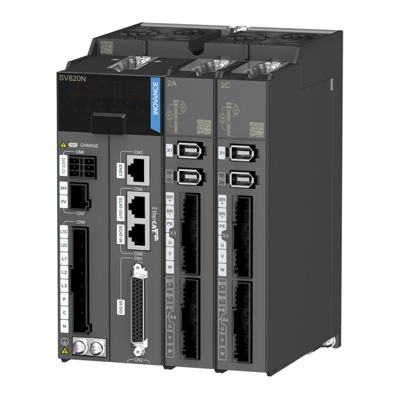
1 Servo System Selection Chapter 1 Servo System Selection Figure 1-1 Components of servo drive Name Purpose The 6-digital 7-segment LED display is used to show servo system’s running state and LED display parameter setting MODE Go to the lower-level menu Execute commands such as storing parameter setting value Change the value of the blinking... - Page 9 1 Servo System Selection Figure 1-2 Wiring example of three-phase 220 V/380 V system Power supply Three-phase 220 V AC Circuit breaker for wiring Used to protect power lines by cutting off the circuit when an overcurrent occurs. Noise filter Avoid the external noise from the power lines by installing a...
-
Page 10: Model And Nameplate Description Of The Servo Drive
MODEL:SV820N1S2C2C Drive model Rated input INPUT:1 PH/3 PH AC 200–240 V 4.5 A/3 A 50/60 Hz OUTPUT:4 x (3 PH AC 0–240 V 2.8 A 0–400 Hz) Rated output S/N:XXXXXXXXXXXXXXXX Manufacturi ng number Suzhou Inovance Technology Co.,Ltd. - 9 -... -
Page 11: Unit Model (Maintenance Options)
1 Servo System Selection 1.1.2 Unit Model (Maintenance Options) Figure 1-5 Unit model description SV82 – M – 2A Unit Model Mark Serial Number Mark SV82 Servo drive Single axis drive unit (rated current) 1.1 A Mark Option Mark 1.6 A Unit module 2.8 A 4.6 A... - Page 12 1 Servo System Selection Item Description 1:5500 (lower limit of speed should allow the drive to Speed range run with rated torque and load) Speed and Speed loop bandwidth 3,000 Hz torque control Torque control accuracy performance Performance ±2% (repeatability) Soft startup time setting 0–60s (acceleration and deceleration can be set) Position control Positioning time 1 ms–10 ms...
-
Page 13: Ethercat Communication Technical Specifications
1 Servo System Selection Check the followings when using the built-in dynamic brake. Note 1. As the dynamic brake has an emergency stop function, do not stop the motor via the disabling signal from the servo drive. If the servo drive starts or stops via power ON/OFF or servo ON/OFF after the command has been input, the dynamic brake circuit operates frequently and it will cause the deterioration and the failure of internal components of the servo drive. -
Page 14: Specifications Of The Servo Motor
Motor Code:14101 IP67 3PHAC Motor code Manufacturing S/N: number 011105424FB00116 Manufacturer: Suzhou Inovance Technology Co., Ltd. Address: No.16, Youxiang Rd, Yuexi Town, Wuzhong District, Suzhou, 215104, People's Republic of China Note The information above only applies to 40\60\80 bases. - 13 -... -
Page 15: Motor Mechanical Characteristics
1 Servo System Selection 1.3.2 Motor Mechanical Characteristics Item Description Rated time Continuous Vibration level Insulation resistance 500 V DC, more than 10M Ω Use in ambient temperature 0–40℃ Excitation mode Permanent magnetic Mounting Mode Flange Heat-resistance level Level F 1,500 V AC, 1 minute (200 V) Insulation voltage 1,800 V AC, 1 minute (400 V) H1:IP67 (except for through shaft section and connectors) -
Page 16: Motor Ratings
0.53 (2.012) ****Z-S *1. The motor with oil seal must be derated by 20% during use. Note *2. Parameters in "()" are for the brake motor. The parameters in the preceding table are the values when the motor works together with the Inovance servo drive and the armature coil temperature is 20℃ . The above table shows the characteristic parameters of the motor after the heatsink below is installed for the motor. MS1H1/MS1H4: 250 x 250 x 6 mm (aluminum) - 15 -... -
Page 17: Motor Overload Characteristics
1 Servo System Selection 1.3.4 Motor Overload Characteristics Load Ratio (%) Running Time (s) Figure 1-8 Motor overload curve Running time (s) 1,000 Load ratio (%) ● The maximum torque of H1 and H4 is 3.5 times the rated torque. - 16 -... -
Page 18: Motor Allowed Radial And Axial Loads
1 Servo System Selection 1.3.5 Motor Allowed Radial and Axial Loads Figure 1-9 Motor radial and axial load diagram Axial load on direction A Axial load on direction B Radial load on direction P Motor Model Allowed Radial Load (N) Allowed Axial Load (N) MS1H1-05B30CB-****Z-S MS1H1-10B30CB-****Z-S... -
Page 19: Motor Torque/Speed Characteristics
1 Servo System Selection 1.3.7 Motor Torque/Speed Characteristics MS1H1 (low inertia, small capacity) Continuous working area Short time working area MS1H1-05B30CB MS1H1-10B30CB Speed (RPM) Speed (RPM) 6,000 6,000 5,000 5,000 4,000 4,000 3,000 3,000 2,000 2,000 1,000 1,000 0.15 0.45 Torque (N·m) Torque (N·m) MS1H1-20B30CB... - Page 20 1 Servo System Selection MS1H1-75B30CB MS1H1-55B30CB Speed (RPM) Speed (RPM) 6,000 6,000 5,000 5,000 4,000 4,000 3,000 3,000 2,000 2,000 1,000 1,000 Torque (N·m) Torque (N·m) MS1H1-10C30CB Speed (RPM) 6,000 5,000 4,000 3,000 2,000 1,000 Torque (N·m) - 19 -...
- Page 21 1 Servo System Selection MS1H4 (medium inertia, small capacity) Continuous working area Short term working area MS1H4-75B30CB MS1H4-40B30CB Speed (RPM) Speed (RPM) 6,000 6,000 5,000 5,000 4,000 4,000 3,000 3,000 2,000 2,000 1,000 1,000 Torque (N·m) Torque (N·m) - 20 -...
-
Page 22: Table Of Servo System Configuration Specifications
1 Servo System Selection Table of Servo System Configuration Specifications Servo Motor Model Rated Maximum Motor Drive Unit Model Capacity Speed Speed Frame Size SV820N**□□□□ MS1H□-□□□□□□□-***** 50 W 05B30CB 1A, 2A 100 W 10B30CB 1A, 2A 200 W 20B30CB 1B, 2B 400 W (low inertia, 40B30CB 1C, 2C small capacity) -
Page 23: Connector Kit
1 Servo System Selection L Length of Cable Name Cable Size Cable Appearance Diagram Cable (mm) S6-L-T04-0.2 S6-L-T04-0.3 S6-L-T04-0.5 Communication cable for S6-L-T04-1.0 1,000 parallel control S6-L-T04-2.0 2,000 of multiple servo motors S6-L-T04-3.0 3,000 S6-L-T04-5.0 5,000 S6-L-T04-10.0 10,000 Connector Kit Item Connector Kit MS1 (Z-S) motor... -
Page 24: Chapter 2 Installation
2 Installation Chapter 2 Installation Installation of the Servo Drive 2.1.1 Installation Environment Requirements Installation location ● Install the servo drive inside a cabinet free from sunlight and rain; ● Install the servo drive in an environment free from corrosive or inflammable gases or combustible goods, such as hydrogen sulfide, chlorine, anmonia, sulphur gas, chloridize gas, acid, soda and salt; ● Install the servo drive in an environment free from high temperature, moisture, dust and metal powder; ●... -
Page 25: Requirements Of The Installation Dimensions And Clearance
2 Installation 2.1.2 Requirements of the Installation Dimensions and Clearance Product dimensions (mm) Figure 2-2 Diagram of physical dimensions 3-M4 tapped hole 122.0 141.0 184.0 167.0 175.0 110.0 Clearance The product can be installed side by side (with the clearance at least 2 mm) in one layer or two layers, as shown in the figure below. When the product is installed in two layers, minimum clearance is required be- tween units. - Page 26 2 Installation A multi-axis system requires units to be lined up along the top. To take the heat dissipation and cooling requirements on units Run settings into full consideration, sufficient installation clearances should be reserved by referring to data in the figure below: Figure 2-4 Installation clearances ≥ 145 mm ≥ 50 mm ≥ 20 mm ≥ 20 mm ≥ 50 mm Installation direction: The product must only be installed vertically, not horizontally or on one side. - 25 -...
-
Page 27: Installation Method
2 Installation 2.1.3 Installation Method This product supports backplate mounting via three installation holes on the body and can be fixed to the installation surface with M4 screws. Installation method: Mark the position of tapped holes for installation on the base plate. Drill holes for fixing the screws on the base plate. This product must be installed on the base plate vertically. Below is the installation diagram: Figure 2-5 Backplate mounting diagram Recommended torque for installation (N.M): When the M4 screws are used to fix the product, the torque is recommended to be 1.2 N.M. Item Electric connection 0.55 - 26 -... - Page 28 2 Installation Cooling Make sure the installation direction of the servo drive is vertical to the wall. Cool the servo drive with natural convection or a cooling fan. As shown in the above figure, keep sufficient space around the drive unit to ensure cooling by fans or natural convection. Install the cooling fans above the servo drive to avoid an excessive temperature rise and main- tain an even temperature inside the control cabinet. Ground The grounding terminal must be properly grounded. Failure to comply may cause electric shock or malfunc- tion due to interference. Cable routing requirements When cabling the servo drive, route the cables downward (refer to the figure below) to prevent liquid on the site from flowing into the servo drive along cables.
-
Page 29: Installation Of The Servo Motor
2 Installation Installation of the Servo Motor 2.2.1 Installation Environment Requirements Installation location ● Install the servo drive in an environment free from corrosive or inflammable gases or combustible goods, such as hydrogen sulfide, chlorine, anmonia, sulphur gas, chloridize gas, acid, soda and salt; ● Use the servo motor with oil seal when the motor is to be used in a place with grinding fluid, oil spray, iron powder or cuttings; ● Install the servo motor away from heat sources such as a heating stove; ● Do not use the servo motor in an enclosed environment. Working in an enclosed environment will lead to a high temperature of the servo motor, which will shorten its service life; ●... -
Page 30: Installation Precautions
2 Installation 2.2.2 Installation Precautions Table 2-2 Installation precautions Item Description Wipe the antirust agent at the shaft extension before installing the servo motor, and then Rust-proof treatment undertake rust-proof treatment. Do not strike the shaft extension during installation. Failure to comply will lead to damage to the internal encoder. ● Use the screw hole at the shaft end when mounting a pulley to the servo motor shaft with a keyway. To fit the pulley, insert a double-end screw into the screw hole of the shaft, put a washer against the coupling end, and then use a nut to push the pulley in. - Page 31 2 Installation Item Description ● Do not immerse the servo motor and cables into oil or water during use. ● Confirm the IP rating of the servo motor when using it in a place with water droplets. (Except for the through shaft section) Flange face The section though the shaft is the part of the shaft that protrudes from the motor head face Drive shaft...
-
Page 32: Physical Dimensions Of The Ms1H1 Series Motor
2 Installation Physical Dimensions of the MS1H1 Series Motor Shaft end diagram Keyed shaft end diagram Motor Model MS1H1-05B30CB-A330Z-S 25±0.5 2 – φ4.5 2.5±0.5 0.5±0.35 MS1H1-05B30CB-A332Z-S 25±0.5 2 – φ4.5 2.5±0.5 0.5±0.35 MS1H1-10B30CB-A330Z-S 77.5 25±0.5 2 – φ4.5 2.5±0.5 0.5±0.35 MS1H1-10B30CB-A332Z-S 25±0.5 2 – φ4.5 2.5±0.5 0.5±0.35 MS1H1-20B30CB-A331Z-S 72.5 30±0.5 4 – φ5.5... - Page 33 2 Installation Weight Motor Model (kg) MS1H1-05B30CB-A330Z-S M3×6 15.5 -0.1 MS1H1-05B30CB-A332Z-S M3×6 15.5 -0.1 MS1H1-10B30CB-A330Z-S M3×6 15.5 -0.1 MS1H1-10B30CB-A332Z-S M3×6 15.5 -0.1 MS1H1-20B30CB-A331Z-S M5×8 16.5 -0.1 MS1H1-20B30CB-A334Z-S M5×8 16.5 -0.1 MS1H1-40B30CB-A331Z-S M5×8 16.5 -0.1 MS1H1-40B30CB-A334Z-S M5×8 16.5 -0.1 MS1H4-40B30CB-A331Z-S M5×8 16.5 -0.1 MS1H4-40B30CB-A334Z-S...
-
Page 34: Chapter 3 Wiring
3 Wiring Chapter 3 Wiring ● Wiring must be performed by professional technicians. CAUTION DAnGER ● To avoid the electric shock, leave the servo drive for more than five minutes after powered off, wait until the power indicator turns off completely, and check the voltage between P and N by using a multimeter. Then, disassemble or assemble the drive. ● Perform wiring after the servo drive and motor are installed properly. Failure to comply will result in electric shock. - Page 35 3 Wiring Drive terminal pin layout: Figure 3-1 Terminal pin arrangement of the SV820N servo drive Communication terminal ENET COM+ +24V COM- ECAT_OUT COM+ +24V COM- Encoder signal ECAT_IN terminal X1/X2 DI18 DI19 DO1+ DI17 DO1- DI20 DI16 BAT+ Brake power BAT- DI21 DO2+ input CN7 DI15...
-
Page 36: Servo Drive Main Circuit Wiring
3 Wiring Servo Drive Main Circuit Wiring 3.1.1 Main Circuit Terminals Main circuit input terminals of the SV820N multi-axis servo drive Figure 3-2 Main circuit terminal arrangement Table 3-1 Names and functions of the main circuit terminals of the SV820N servo drive Terminal Terminal Name Terminal Function... -
Page 37: Examples Of Bleeder Resistor Incorrect Wiring
3 Wiring 3.1.2 Examples of Bleeder Resistor Incorrect Wiring Figure 3-3 Connection diagram of the external bleeder resistor The external regenerative resistor Braking resistor connected terminals are not connected between P and C Observe the following precautions when connecting the external bleeder resistor: Do not directly connect the external bleeder resistor to the bus’s positive pole (P) and negative pole (N). Failure to comply will lead to damage of the servo drive or a fire. -
Page 38: Recommended Models And Specifications Of The Main Circuit Cables
The figure below shows the connectors of the main circuit cables. These connectors accompany the com- plete drive (model to be complemented at the time of producing in batches). Figure 3-4 Figure of the main circuit cable connectors Table 3-2 Recommended main circuit cable and cable model for SV820N series servo drive Recommended Recommended Recommended... -
Page 39: Power Supply Wiring Example
3 Wiring 3.1.4 Power Supply Wiring Example Models using single-phase 220 V power: SV820N1S2C2C Figure 3-5 Main circuit wiring for single-phase 220 V power Single-phase 220 V AC Servo Drive Noise filter Stop button X1/X2 Main circuit power input button contactor Surge protection device (SPD) ALM- Servo alarm output relay ALM+... - Page 40 3 Wiring Figure 3-6 Main circuit wiring for three-phase 220 V power Three-phase 220 V AC Servo drive Noise filter Stop button Main circuit power input X1/X2 contactor button Surge protectio n device (SPD) ALM- Servo alarm output relay ALM+ Servo alarm signal output Servo alarm...
-
Page 41: Precautions For Main Circuit Wiring
3 Wiring 3.1.5 Precautions for Main Circuit Wiring Do not connect the input power cables to the output terminals U, V and W. Failure to comply will cause damage to the servo drive. When cables are bundled in a duct, take current reduction into consideration since the heat dissipation condition deteriorates. When temperature inside the cabinet is higher than the temperature limit of the cables, select those cables with a higher temperature limit. Teflon cables are recommended. As the surface of general ca- bles is easy to harden and break, take thermal insulation measures for cables laid in a low temperature environment. -
Page 42: Specifications Of Main Circuit Peripheral Parts
3 Wiring 3.1.6 Specifications of Main Circuit Peripheral Parts Recommended circuit breaker and electromagnetic contactor: Table 3-5 Models of recommended circuit breaker and electromagnetic contactor Recommended Circuit Breaker Recommended Contactor Main Circuit Power Supply Drive Model Current (A) Schneider Model Current (A) Schneider Model SV820N1S**** Single/Three-phase 220 V OSMC32N3C6 LC1 D09 SV820N2S**** Wiring of Motor Cables Between Servo Drive and Servo Motor A complete servo drive consists of two drive units with each drive unit supporting two motors. -
Page 43: Wiring Of Power Cables Between The Servo Drive And Servo Motor
3 Wiring Wiring of Power Cables Between the Servo Drive and Servo Motor 3.3.1 Wiring of the Motor Power Cables with the Brake Figure 3-7 Example of connecting the servo drive and servo motor Brown-BK+ Blue-BK- White-U Black-V Red-W Yellow/Green-PE Power supply (24 V DC) Table 3-6 Connectors of power cables on the servo motor side Frame Size of Connector Appearance Terminal Pin Layout... -
Page 44: Wiring Of The Motor Power Cables Without The Brake
3 Wiring Note Frame size of the motor indicates the width of the motor flange. The power cable colors are subject to the actual cables. The cable colors mentioned in the guide are colors of all Inovance cables. 3.3.2 Wiring of the Motor Power Cables without the Brake When motors without a brake are connected to the drive, it is not necessary to connect the two brake signal terminals (BR+ and BR–), as shown in the figure below. Other connections should be performed in the same way as the motors with brake. Refer to "3.3.1 Connec- tion of power cables of motor with a brake" for details. Figure 3-8 Connection diagram of power cables of a motor without a brake White-U Black-V Red-W Yellow/Green-PE... -
Page 45: Wiring Of Encoder Cables
The encoder cable colors are subject to the actual cables. The cable colors mentioned in the guide are colors of all Inovance cables. Table 3-7 Connectors of SV820N series 20-bit encoder cables on servo drive side Connector Appearance Terminal Pin Layout Pin No. - Page 46 3 Wiring Table 3-8 Connectors of SV820N series 20-bit encoder cables (9-pin connector) Frame Size of an Adaptable Connector Appearance and the Terminal Pin Layout Motor [Note] Connect to drive encoder signal Encoder signal terminals connector Encoder outgoing line Visual-in through...
- Page 47 3 Wiring Table 3-9 9-pin connection relation of 20-bit encoder cables of SV820N series Motor Side DB9 on Servo Drive Side Function Description 20-29 Aviation Plug 9 PIN Signal Pin No. Pin No. Pin No. Serial communication signal + Serial communication signal -...
-
Page 48: Connection Of Absolute Encoder Cable
3 Wiring 3.4.2 Connection of Absolute Encoder Cable Figure 3-10 Example of connection of signal cable and battery box of absolute encoder Battery box Encoder signal cable Battery box Color of battery box outer lead: Figure 3-11 Battery box outer lead of absolute encoder Red: Positive Black: Negative... - Page 49 3 Wiring Specification of absolute encoder cables Table 3-11 Connectors of SV820N series 20-bit encoder cables (9-pin connector) Frame Size of the Connector Appearance and the Terminal Pin Layout Adaptable Motor [Note] Connect to drive encoder Encoder signal Encoder outgoing line signal terminals connector...
- Page 50 3 Wiring Installing the battery box ● Model of the battery box accessory: SV82-C4, including: 1 plastic box 1 battery (3.6 V, 2,600 mAh) Terminal block and crimping terminal ● Installation of the battery box: Figure 3-12 Installation diagram of the battery box for the absolute encoder Directly insert the battery box into the corresponding slot on the drive, ensure it is inserted correctly to prevent loosening.
- Page 51 3 Wiring Improper use of battery may result in battery leakage which will corrode the components or Note cause the battery to explode. Observe the following precautions during use: 1. Place the battery in the correct +/– polarity; 2. If you place a battery that has been used for a long time or a dead battery in the device, battery leakage may occur, corroding surrounding components; as the battery is conductive it may cause a short circuit. Replace the battery periodically (recommended period: Every 2 years). 3. NEVER decompose the battery, so as to prevent personal injury by spraying of electrolyte. 4.
- Page 52 3 Wiring Theoretical lifetime of battery: The calculation below only considers the current consumed by the encoder and does not cover the current consumed by the battery itself. Assume that the drive works normally for T1 in a day, the motor rotates for T2 after the drive is powered off, and the motor stops rotating for T3 after power off [unit: hour (H)] Example: Table 3-13 Theory lifetime of absolute encoder battery Item Working Time 1 Working Time 2 Number of days the battery works under different...
-
Page 53: Wiring To Control Signal Terminal Cn1 Of Servo Drive (Di/Do)
3 Wiring Wiring to Control Signal Terminal CN1 of Servo Drive (DI/DO) Figure 3-13 Pin layout of control circuit terminal connector of servo drive COM+ +24V COM- COM+ +24V COM- DI18 DI19 DO1+ DI17 DI20 DO1- DI16 DI21 DO2+ DI15 DI22 DO2- DI14... - Page 54 3 Wiring It is recommended to use 24–26 AWG cables. Table 3-14 DI/DO signal description Signal Pin No. Function Description Signal Pin No. Function Description Digital output signal 1 High-speed digital input signal 1 DO1+ (positive terminal) Digital output signal 1 High-speed digital input signal 2 DO1- (negative terminal)
-
Page 55: Di Circuit
3 Wiring 3.5.1 DI Circuit DI1 – DI24 interface circuits are the same, in which the input current limiting resistor for DI1–DI16 is 2.4 kΩ. The following takes DI17 interface circuit as an example. Servo drive High-speed input internal circuit for DI1−DI16 COM+ 2.4 kΩ Normal input internal circuit for DI17−DI24 COM+ 4.7 kΩ DI17 When the host controller provides relay output: ● When the internal 24 V power supply of the servo drive is used: Servo drive +24 V power supply COM+ 4.7 kΩ... - Page 56 3 Wiring ● When the external power supply is used: Servo drive External +24 V DC COM+ 4.7 kΩ DI17 Relay External 0 V Servo Drive External +24 V A single power +24 V supply is not used power supply COM+ 4.7 kΩ DI17 Relay COM- External 0 V - 55 -...
- Page 57 3 Wiring When the host controller provides OC output: ● When the internal 24 V power supply of the servo drive is used: Servo drive Servo drive +24 V +24 V power power supply supply COM+ COM+ 4.7 kΩ 4.7 kΩ DI17 DI17 COM- COM- ● When the external power supply is used: Servo drive Servo drive External External +24 V DC +24 V DC...
-
Page 58: Do Circuit
3 Wiring 3.5.2 DO Circuit DO1–DO6 interface circuits are the same. The following takes DO1 interface circuit as an example. When the host controller provides relay input: Servo drive External 5−24 V DC Relay DO1+ DO1- External 0 V Note When the host controller provides relay input, a flywheel diode must be installed, otherwise, the DO ports may be damaged. Servo drive Servo drive External External 5−24 V DC 5−24 V DC A relay is not Relay... -
Page 59: Wiring To Communication Signal Connectors (Cn4/Cn5)
3 Wiring When the host controller provides optocoupler input: Servo drive Servo Drive External External The current limiting 5−24 V DC 5−24 V DC resistor is not connected Optocoupler Optocoupler DO1+ DO1+ DO1- DO1- External 0 V External 0 V The maximum allowable voltage and current of the optocoupler output circuit inside the servo Note drive are as follows:... - Page 60 3 Wiring Figure 3-15 Communication wiring diagram EtherCAT Multi-device ECAT_OUT communication cables for the servo drive ECAT_IN 0 1 2 3 4 5 6 7 CANRUN EtherCAT CANERR /STOP Servo drive and PLC communication cables Communication signal connectors (CN4 and CN5) are EtherCAT interface connectors. The interface line from the master station is connected to CN5 (IN), and CN4 (OUT) is connected to the next slave device.
-
Page 61: Selection Of Communication Cables
3 Wiring 3.6.2 Selection of Communication Cables Selection principle Specification Supplier 0.2 m–10 m Inovance More than 10 m Haituo Basic information about EtherCAT communication cables of Inovance Cable models are as follows: S6-L-T04-3.0 Cable Length (Unit: m) Mark Product Series Mark Length Mark Length S6 series 0.2 m... -
Page 62: Wiring Of Signal Connector Between Background Communication And Online Upgrade (Cn3)
3 Wiring Wiring of Signal Connector Between Background Communication and Online Upgrade (CN3) Arrangement of Ethernet(CN3) terminals: Figure 3-16 Ethernet connector terminal Pin definition of CN3 (Ethernet connector terminal) is the same as that of CN4/CN5. Refer to Table 4-27 for details. Table 3-16 Pin definition of communication signal terminal connectors Pin No. Signal Function Description Terminal Pin Layout Data transmit+ Data transmit- Data receive+ Data receive– Housing Shield Note Communication cables are the same as cables for multi-device communication (S6-L-T04). - 61 -... -
Page 63: Anti-Interference Measures For Electrical Wiring
3 Wiring Anti-interference Measures for Electrical Wiring Take the following measures to suppress interference: Ensure that the reference input cable is shorter than 3 m, and the encoder cable is shorter than 20 m and both types of cables are shielded twisted pair. Use a thick cable as the grounding cable. (Recommended to be more than 2.0 mm D class (or higher class) grounding is recommended (grounding resistance is below 100 Ω). Use one-point grounding. Use a noise filter to prevent radio frequency interference. For a home application or an application with noise interference, install the noise filter on the input side of the power supply line. -
Page 64: Using A Noise Filter
3 Wiring Grounding To prevent potential magnetic interference, conduct grounding correctly according to the following instruc- tions. ■ Grounding the servo motor housing Connect the grounding terminal of the servo motor to the PE terminal of the servo drive and correctly ground the PE terminal, to reduce potential magnetic interference. - Page 65 3 Wiring ● Separate the grounding cable and output power supply lines of the noise filter. Figure 3-19 Diagram for separated cabling of noise filter grounding cable and output cable Noise Noise filter filter ● Use a separate grounding cable as short and thick as possible for the noise filter. Do not share the grounding cable with other grounding devices. Figure 3-20 Single point grounding diagram Noise Noise filter...
-
Page 66: Precautions Of Using Cables
3 Wiring ● Grounding the noise filter inside the cabinet If the noise filter and the servo drive are installed in the same cabinet, fix the noise filter and the servo drive on the same metal plate. Make sure the contact part is in good conductive condition, and ground the metal plate properly. Figure 3-21 Diagram for noise filter grounding Noise Servo filter drive Servo drive Shield grounding Ground Precautions of Using Cables Do not bend or apply tension to cables. The core wire of a signal cable is only 0.2 or 0.3 mm in diameter and easily broken. Handle the cables carefully. -
Page 67: 3.10 Overall Wiring
3 Wiring 3.10 Overall Wiring Figure 3-23 Overall wiring diagram Servo drive TX+ 1 TX+ 1 RX+ 3 RX+ 3 DO1+ RX- 6 RX- 6 DO1- Host controller TX+ 1 TX+ 1 DO2+ State DO2- output Note 4 RX+ 3 RX+ 3 DO3+ RX- 6... -
Page 68: Chapter 4 Operation Panel
4 Operation Panel Chapter 4 Operation Panel Operation Panel Composition Figure 4-1 Appearance of the LED operation panel LED display area Operation MODE buttons The operation panel of the SV820N servo drive consists of an LED (6-digit, 7 segments) and 6 buttons. The operation panel is used for the servo drive display, parameter setting, user password setting and general functions operations. -
Page 69: Display Of The Operation Panel
4 Operation Panel Display of the Operation Panel ● Transition relation between the operation panel display and the host controller operation object The following mapping relation exists between the function code (decimal) for the panel display and the operation object dictionary of the host controller (hexadecimal, "Index" and "Sub-index"), and should be noted in use: Object dictionary index = 0 x 2000 + function code group No.;... -
Page 70: State Display
4 Operation Panel ● In parameter display mode, set H02-32 and select the parameters to be pre-monitored, and the opera- tion panel switches to the monitoring display mode. ● Once a fault occurs, the operation panel immediately enters the fault display mode, and all 5-digit LEDs blink. Press the SET key to stop the LED blinking, and then press the MODE key to switch over the parameter display mode. -
Page 71: Parameter Display
CN5 connection physical layer. EtherCAT is output indication 4.2.2 Parameter Display The SV820N series has 14 groups of function codes based on parameter functions. The function codes can be located quickly based on the group it belongs to. Refer to the appendix to view the function code table. In this section, the current operation axis 3 is taken as an example. Parameter group display Display Name Content XX: Function code group number HXX.YY... - Page 72 4 Operation Panel ■ With-symbol number of above 4 digits and without-symbol number of above 5 digits The number is displayed in digits from low to high in pages. Each 5 digits are displayed in a page. The display method is: current page + value of current page. As shown in the following figure, hold down "SHIFT" for more than 2 seconds to switch to the next page.
- Page 73 4 Operation Panel Display Name Situation Meaning Use One-key One-key Self-adjustment is in TunE Self-adjustment progress. function. Use One-key One-key Self-adjustment has FAIL Self-adjustment failed. function. Fault display (taking the current operation axis 3 as an example) ● The keypad displays the current or history faults and warning codes. For analysis and rectification of faults and warnings, refer to Chapter 5. ●...
-
Page 74: Parameter Monitoring
4 Operation Panel Parameter Monitoring Group H0B of the servo drive: Displays the parameters for monitoring the running status of the servo drive. The display of H0B monitoring is described as follows: Function Name Unit Meaning Display Examples Code 3,000 RPM is displayed as follows: The actual servo motor speed after Actual motor H0B-00 round-off is displayed, in unit of 1 speed –3,000 RPM is displayed as follows: RPM. 3,000 RPM is displayed as follows: The current speed reference of the H0B-01 Speed reference servo drive is displayed. - Page 75 4 Operation Panel Function Name Unit Meaning Display Examples Code For example, when the optocoupler of terminal DI1 is and that of DI2–DI24 is The corresponding binary value is "11111111 11111111 11111110" The value of H0B-03 read by It indicates the corresponding the commissioning software is 0xFFFFFE.
- Page 76 4 Operation Panel Function Name Unit Meaning Display Examples Code 1073741824 referent units display: Absolute SHIFT It indicates the current absolute position counter Reference H0B-07 position of the motor (reference unit (32-bit decimal unit). display) SHIFT 360.0° is displayed as follows: Mechanical It indicates the current mechanical H0B-09 0.1°...
- Page 77 4 Operation Panel Function Name Unit Meaning Display Examples Code 10,000 encoder units is displayed as follows: Deviation of the encoder position = Encoder position deviation Total input position references Encoder counter H0B-15 (encoder unit) - unit (32-bit decimal Total encoder feedback pulses SHIFT display) (encoder unit)
- Page 78 4 Operation Panel Function Name Unit Meaning Display Examples Code After 220 V AC rectification, 311.0 V is displayed as follows: H0B-26 Bus voltage 0.1 V DC bus voltage of main circuit 27℃ is displayed as follows: It indicates the temperature of the ℃ Module H0B-27 power module inside the servo temperature drive. It sets the number of history faults to be viewed.
- Page 79 4 Operation Panel Function Name Unit Meaning Display Examples Code 3,000 RPM is displayed as follows: It indicates the servo motor speed when the fault displayed in H0B-34 Motor speed occurs. H0B-37 upon displayed –3,000 RPM is displayed as follows: fault When there is no fault, H0B-37 display is "0." It indicates the winding current 4.60 A is displayed as follows: effective value of the servo motor...
- Page 80 4 Operation Panel Function Name Unit Meaning Display Examples Code For example, the value of H0B-41=0x431 read by the commissioning software is: The corresponding binary value is "00000000 00000100 00110001." The keypad display is as follows: It indicates the high/low level state of the 24 DI terminals when the fault displayed in H0B-34 occurs.
- Page 81 4 Operation Panel Function Name Unit Meaning Display Examples Code 3,000.0 RPM is displayed as follows: SHIFT Actual motor It indicates the actual servo motor H0B-55 0.1 RPM –3,000.0 RPM is displayed as speed speed, precision to 0.1 RPM. follows: SHIFT 12.0 V is displayed as follows: Control power It indicates the control power DC H0B-57 0.1 V voltage...
- Page 82 4 Operation Panel Function Name Unit Meaning Display Examples Code Example: 8388607 Encoder unit Absolute encoder single- Encoder It displays the single-turn position H0B-71 turn position unit feedback of the absolute encoder. SHIFT feedback Example: 2147483647 encoder unit SHIFT Position (low It displays the absolute position 32 bits) of Encoder H0B-77 (low 32 bits) of the motor when the the absolute...
- Page 83 4 Operation Panel Function Name Unit Meaning Display Examples Code Example: 1073741824 referent unit SHIFT Rotating load It displays the mechanical absolute Reference H0B-85 single-turn position when the absolute system unit position works in rotating mode. SHIFT - 82 -...
-
Page 84: Parameter Setting
4 Operation Panel Parameter Setting Parameter setting can be performed on the keypad of servo drive. For details on the parameters, refer to Chapter 8. The following figure shows the keypad operation of switching the position control mode to the speed control mode after the power is on. Figure 4-5 Diagram for keypad operation of parameter setting Servo state display Servo ready MODE MODE Parameter group display MODE... -
Page 85: User Password
4 Operation Panel User Password After the user password function (H02-30) is enabled, only the authorized user has the parameter setting rights; other operators can only view the parameters. 4.5.1 Setting User Password The following takes the operation of setting the password to "00001" for example. Figure 4-6 Diagram for keypad operation of user password setting Start Power On See parameter settings for H02-30... -
Page 86: Jog Running
4 Operation Panel Jog Running ● When using the jog running function, set the S-ON signal inactive. Otherwise, this function Note cannot be used. ● Use the jog running function to perform trial running on the servo motor and drive. 4.6.1 Operation Method Figure 4-7 Diagram for keypad operation of jog running setting... -
Page 87: Di/Do Function
4 Operation Panel DI/DO Function There are 24 DI signals and 6 DO signals on terminal CN1 of SV820N. H03 (terminal DI function allocation and logic selection) and H04 (terminal DO function allocation and logic selection) can be used by multiple axes. On any axis, setting and modifying functions of DI and DO terminals can be performed on keypad. -
Page 88: Di Function Setting
4 Operation Panel Code Name Function Name Description Remark Invalid - The absolute value of motor speed after filter is smaller than the setting value of function code H06-16; TGON Motor rotation Valid - The absolute value of motor speed after filter reaches the setting value of function code H06-16 Valid - Servo drive reports warning;... -
Page 89: Do Function Setting
4 Operation Panel 4.7.3 DO Function Setting In this section, function setting of H04-00 is taken as an example. Function number setting of H04 consists of three decimal digits. The first digit is for the setting axis No. and last two digits are for specific terminal functions. The diagram is shown in the red dotted box below: Figure 4-9 Diagram for keypad operation of DO function setting Servo state display Servo ready MODE 3 11 MODE Parameter group display Axis number Terminal function 3: Axis 3 11: Fault signal MODE Offset display in the group Parameter display MODE... -
Page 90: Chapter 5 Troubleshooting
5 Troubleshooting Chapter 5 Troubleshooting Fault and Warning Grading Fault and warning grading Faults and alarms are graded into the following three levels based on degree of severity: NO.1 > NO.2 > NO.3. NO.1 non-resettable fault NO.1 resettable fault NO.2 resettable fault NO.3 resettable warning "Resettable" means that the keypad stops displays of faults/warnings once the "reset signal" is input. To reset a fault/warning, use one of the following two methods: Set 200D-02h=1 (fault reset enabled). Enable the rising edge of the control word 0x6040 bit7 on the host controller. To reset a NO.1 fault and a NO.2 fault, turn off the S-ON signal and input the fault reset signal. -
Page 91: Communication Fault And Warning Code List
5 Troubleshooting Communication Fault and Warning Code List When communication or the servo drive is abnormal, the SV820 servo drive sends an emergency message to the network as a producer, or sends a response abort message when the SDO transmission is abnormal. Fault code list (take the current operation axis 3 as an example): Display Fault Name Fault Type Resettable or Not Fault Range... - Page 92 5 Troubleshooting Display Fault Name Fault Type Resettable or Not Fault Range E3.420 Main circuit phase loss NO.2 Equipment fault E3.430 Control power undervoltage NO.1 Equipment fault E3.500 Motor overspeed NO.1 Shaft fault E3.602 Angle auto-tuning failure NO.1 Shaft fault E3.610 Servo drive overload NO.2...
- Page 93 5 Troubleshooting Warning code list (take the current operation axis 3 as an example) Display Name Fault Type Resettable or Not Fault Range E3.601 Home attaining warning NO.3 Shaft fault E3.730 Encoder battery warning NO.3 Shaft fault E3.760 Encoder overheat NO.3 Shaft fault E3.909...
-
Page 94: Troubleshooting Of Faults
5 Troubleshooting Troubleshooting of Faults Note Take the current operation axis 3 as an example. ■ E3.101: system parameter abnormal Cause: The total number of parameters changes, which generally occurs after software updates. The actual parameter values of group 2002h and later exceed the limit, which generally occurs after software updates. - Page 95 Probable Cause Confirming Method Corrective Action View the FPGA software version (2001-03h) and the 1. The FPGA software CUP0 software version (2001-04h) and the CUP1 software Contact Inovance for version and the version (2001-05h) via the keypad or the Inovance servo technical support. Update software version of commissioning software. Check whether the non-zero the software to make them...
- Page 96 2. Instantaneous power failure Check whether instantaneous power Write the parameters of serial occurs during serial encoder failure occurs during serial encoder encoder motor by using Inovance motor parameter writing. motor parameter writing. commissioning software. Set drive model (2001-0Bh) Check whether the software is incorrectly, and power on the system, 3.
- Page 97 5 Troubleshooting ■ E3.120: product model matching fault Cause: The motor model and drive model do not match or the parameter setting is incorrect, or the inverter module recognition is incorrect. Probable Cause Confirming Method Corrective Action Internal fault code 200B-2Eh=1120 Set 2000-01h (Motor SN) correctly View the motor nameplate to check whether according to the motor nameplate or...
- Page 98 Probable Cause Confirming Method Corrective Action 1. The servo drive View the servo drive and servo motor nameplates model and the to check that the equipment used is the Inovance Replace the matching servo drive and motor model do not SV820 series, servo drive and matching servo servo motor. match.
- Page 99 You can view Carry out gain adjustment. oscillates. "current feedback" by using the drive Inovance servo commissioning software. Check whether the encoder cable is used according to the standard configuration. Check whether the cable 7. The encoder cable is aging, corrosive or loose.
- Page 100 5 Troubleshooting E3.208: FPGA sampling operation timeout Cause: Find th e cause through the internal fault code (200B-2Eh) when E3.208 occurs. Probable Cause Confirming Method Corrective Action Use the recommended encoder cable. If a non- standard cable is used, check that it complies with Internal fault code 200B-2Eh=2208 the specifications and is a shielded twisted pair cable.
- Page 101 3. The encoder model is set Inovance SV820 series servo drive nameplates to check that the equipment incorrectly or the wiring is and 20-bit servo motor, ensure used is the Inovance SV820 series servo incorrect. that 2000-01h=14000. Correct the drive and 20-bit servo motor (-U2***). motor model, encoder type, and encoder wiring.
- Page 102 Check whether 200B-1 Bh (bus voltage) is within the following specifications: 6. The bus voltage 220 V drive: 200B-1Bh > 420 V sampling value has a Contact Inovance for technical support. Measure the DC bus voltage between large deviation from the P and C and check whether the DC actually measured value. bus voltage is normal and smaller than 200B-1 Bh.
- Page 103 5 Troubleshooting Probable Cause Confirming Method Corrective Action Replace the cables and wire the power 4. Phase loss exists: Single- Check whether the main circuit wiring cables correctly: phase power supply is is correct and reliable, and whether the used for the 3-phase phase loss fault detection (200A-01h) is Three-phase: R, S, T servo drive.
- Page 104 Set the speed limit value smaller than the overspeed threshold. Check whether the "speed feedback" exceeds 4. The motor speed Adjust the gain or mechanical the overspeed threshold through the Inovance overshoots. running conditions. servo commissioning software. The fault persists after the servo drive is 5.
- Page 105 Connect the wirings according to the correct wiring diagram. Preferably use the cables 1. Wiring of the motor and Check wirings between the servo drive, the servo recommended by Inovance. encoder is incorrect or in motor and the encoder according to the correct When self-made cables are poor contact.
- Page 106 5 Troubleshooting Probable Cause Confirming Method Corrective Action Check the running reference and motor speed (200B-01h) through Inovance servo commissioning software or the keypad: Running reference in position control: 200B-0Eh (Input position reference counter) 6. Locked-rotor occurs due to mechanical factors, Running reference in speed mode: 200B-02h Eliminate mechanical factors. resulting in very heavy (Speed reference) load during running. Running reference in torque mode: 200B-03h (Internal torque reference) Check that the running reference is not 0 but the motor speed is 0 in the corresponding mode.
- Page 107 5 Troubleshooting ■ E3.650: Heatsink overheat Cause: The temperature of the servo drive power module is higher than the over-temperature protection threshold. Probable Cause Confirming Method Corrective Action Improve the cooling conditions for 1. The ambient Measure the ambient temperature the servo drive to reduce the ambient temperature is too high.
- Page 108 Check on-site wirings: Preferably use the cables Check whether large equipment is generating an interference recommended by Inovance. on-site and whether there are interference sources such as If a non-standard cable is used, various variable-frequency devices inside the cabinet. check whether the cable meets Set the servo in "Rdy" state, then manually rotate the motor...
- Page 109 UVW cable or the encoder Check wirings. cables correspondingly. If necessary, cable breaks. replace all cables and ensure a reliable connection. Check the running reference and motor speed (200B-01h) through Inovance servo commissioning software or the keypad: Running reference in position control: 200B-0 Eh (Input position reference counter) 3. Locked-rotor occurs Running reference in speed mode: 200B-02h due to mechanical Eliminate mechanical factors.
- Page 110 5 Troubleshooting ■ E3.B01: Position reference suffers abnormal increment Cause: Target position increment in CSP mode is too large. Probable Cause Confirming Method Corrective Action Decrease the position reference 1. The position reference Check the target position increment of the speed, or set a certain acceleration/ increment is too large. adjacent synchronous cycles.
-
Page 111: Troubleshooting Of Warnings
Connect the wirings according to the correct wiring diagram. Preferably use the cables 1. Wiring of the motor and Check the wiring between the servo recommended by Inovance. encoder is incorrect or in drive, servo motor and the encoder When self-made cables are used, poor contact. - Page 112 2001-0Bh model is set incorrectly. and servo drive model in 2001-0Bh. correctly and use a matching servo motor according to Section 2.3. Check the running reference and motor speed (200B-01h) through Inovance servo commissioning software or keypad: Running reference in position control: 200B-0Eh (Input position reference counter) 6.
- Page 113 5 Troubleshooting Probable Cause Confirming Method Corrective Action Set H02-25 correctly: 2. The setting of H02-25 is incorrect View the setting value of H02-25. H02-25=1 (external, naturally when the external bleeder resistor ventilated) Measure the resistance of the is used. external resistor between P and H02-25=2 (external, forcible cooling) C, and compare it with the bleeder Select a proper bleeder resistor...
- Page 114 5 Troubleshooting ■ E3.939: Motor power cable breaking Cause: The actual phase current of the motor is smaller than 10% of the rated motor current, and the actual motor speed is small but the internal torque reference is very large. Probable Cause Confirming Method Corrective Action...
- Page 115 5 Troubleshooting ■ E3.980: Encoder internal fault Cause: An encoder algorithm error occurs. Probable Cause Confirming Method Corrective Action If the servo drive is powered off and on several times An encoder internal but the warning is still reported, it indicates that the Replace the servo motor.
-
Page 116: Troubleshooting Of Communication Faults
5 Troubleshooting Troubleshooting of Communication Faults The above provides the details for rectifying faults of the SV820 series servo drive. This part describes how to rectify communication faults. ■ E3.E07: network state switching abnormal Cause: When the servo is enabled, the network switches from OP to non-OP. Probable Cause Confirming Method Corrective Action 1. - Page 117 Measure the synchronization cycle of the controller. 1. The controller has a large Measure the synchronization cycle Increase the factory synchronization cycle through a digital oscilloscope or the oscilloscope parameter (200E-21h). error. function in the Inovance servo commissioning software. - 116 -...
-
Page 118: Chapter 6 Trial Running
6 Trial Running Chapter 6 Trial Running Check Before Running Check the items in the following table before running the servo drive and motor. Checklist before running Record Content Wiring □ The servo drive's main circuit power input terminals are connected correctly. The main circuit output terminals U, V, W of the servo drive are properly connected to the power □... -
Page 119: Jog Running Via Commissioning Software
6 Trial Running Jog Running via Commissioning Software Note: When performing background jog running, the current control mode of the corresponding shaft shall not be in the EtherCAT control mode. 6.4.1 Communication Setting First open the commissioning software InoDriveShop.exe of SV820N. Then with InoDriveShop (background commissioning software), various functions can be performed on thePC, such as real-time monitoring, pa- rameter configuration, real-time sampling, triggering single sampling and an emergency stop. The software icon is as follows: Select the corresponding serial number and baud rate from the Communication Wizard. Double click the icon to open the software, then directly load connected devices: The current device can also be identified by automatic search function: - 118 -... -
Page 120: Jog Running
6 Trial Running 6.4.2 Jog Running Enter Speed JOG mode operation interface, and complete jog running on 4 shafts respectively. Function description: The Speed JOG function is mainly used for motor speed mode commissioning. Select the corresponding axis number in the axis drop-down box, set the commissioning speed in JOG speed, set the servo status as servo On, then the motor will be enabled. At this point, click and hold the left arrow button and the motor will run forward at the set JOG speed and will stop upon release. Similarly, press and hold the right arrow button which will cause the reverse running. -
Page 121: Cyclic Synchronous Position (Csp) Mode Of Sv820N With Am600 Controller
6 Trial Running Cyclic Synchronous Position (CSP) Mode of SV820N with AM600 Controller The following will introduce the communication settings of SV820N by taking Inovance’s AM600 controller as the master station. Note To better fit for SV820, it is recommended to use Version 1.10 or higher version for AM600 background. 6.5.1 Creating a Project Create an AM600 project. Select "AM600-CPU1608TP," as shown in the following image. 1. Select a project. - Page 122 6 Trial Running Click Scan Network. Select the scanned AM600 device. Now the communication connection between PLC and PC is completed. Next, perform the device configuration. When the AM600 device cannot be scanned in InoPro: The CoDeSys gateway is not turned on. Note Please check and start it, and then scan. Check whether the CoDeSys gateway is turned on (shown in color). If it is in STOP state, please click it to start. - 121 -...
-
Page 123: Adding Devices For The Configuration
6 Trial Running 6.5.3 Adding Devices for the Configuration Add the XML file of SV820N: Click Import ECT File in Network Configuration to add XML files (please download XML files from Inovance’s official website). Perform device configuration for the system: First add the EtherCAT bus, then add the SV820N device. (Directly drag the SV820N_ECAT_V0.10 into the configuration interface.) - 122 -... - Page 124 6 Trial Running If AM600 background is lower than V1.10, please manually add 4 motor shafts. Right-click the SV820N device option to add 4 rotating motor shafts. Configure master station communication parameters for EtherCAT: Just use the default value, and select eth1 for the network. - 123 -...
-
Page 125: Configuring The Pdo Mapping For The Slave Station
6 Trial Running 6.5.4 Configuring the PDO Mapping for the Slave Station Enable expert settings Check the corresponding PDO list. On PDO configuration interface, process data required by 4-axis CSP mode can be configured. Click SV820N (SV820N_ECAT_v0.10) list. - 124 -... -
Page 126: Axis Scaling Settings
6 Trial Running The PDO list configured according to the CSP (Location) + CSV (Speed) + TP (Probe) mode is as follows. 6.5.5 Axis Scaling Settings - 125 -... -
Page 127: Plc Program
6 Trial Running 6.5.6 PLC Program Add an FB file that edits the function block in the application. - 126 -... - Page 128 6 Trial Running The definition part of FB Five function blocks in FB - 127 -...
- Page 129 6 Trial Running Add another POU as shown in step 1. Add the FB function block to the newly created POU. Codes are as follows: - 128 -...
- Page 130 6 Trial Running Instantiate this FB into four function blocks, and assign to four axes respectively. After calling this program in the Ethercat task, simple enabling, jog, homing, absolute position operation can be perfomed. - 129 -...
-
Page 131: Commissioning Sv820N With Omron Nj Series Controller
6 Trial Running Log in to the PLC to operate the bus manually. Commissioning SV820N with Omron NJ Series Controller 6.6.1 Network Configuration Settings After creating a new project, on EtherCAT device interface, select the master station icon and right-click to open the menu bar, then click "Show ESI Library." Note Add the XML file of SV820N (please download XML files from Inovance’s official website). - 130 -... - Page 132 6 Trial Running In the ESI Library list, open the link below ("The folder") and put the ".xml document" corresponding to the SV820N into the folder. Then exit and reopen the Sysmac Studio software to make it effective. - 131 -...
- Page 133 6 Trial Running On the upper right of the software, click on all suppliers, then select Inovance in the drop-down menu. Then double-click SV820N in the device list below to add the device to the configuration list. (If the net- work is already configured, skip to step 4 and use the online upload configuration.) - 132 -...
- Page 134 6 Trial Running The SV820N is a 4-in-1 drive and plans the usability for the PDO list of each axis. Select the mode you want to run from "CSP/CSV+TP, CSP+TP, CST, CSP/CST+TP, CSP/CST/CSV+TP, PP+TP, PP\PV\ PT+TP." In conjunction with the controller, the XML file will select the PDO list needed by the current mode. In this example, select CSP/CST/CSV+TP mode for all axes. - 133 -...
- Page 135 6 Trial Running Set the EtherCAT communication site address through H0E-21 (currently available only for NJ, and there is no need to configure Beckhoff Twincat). Power on again after setting. For easier configuration management , it is recommended to set the address according to the actual physical connection order. Set the master station modification as online mode, and compare and merge with the physical network configuration in the menu bar. Set the actual physical network configuration to Sysmac software’s net- work configuration. - 134 -...
-
Page 136: Commnucation Data Configuration
6 Trial Running 6.6.2 Commnucation Data Configuration Motion control axis settings Add axis settings in motion control. Double-click "MC_Axis000" as shown below. Then configure the SV820N device for the corresponding site in the related axis basic settings page. "MC_Axis000" can be renamed (Chinese is applicable). For example, when named as "右放卷 (right unwinding)," then the use of "右放卷"... - Page 137 6 Trial Running Variable configuration for servo axis communication mapping Click the detailed settings to expand the configuration parameters, then follow the table for the object map- ping configuration and carefully check it. The axis configuration of the IS820N needs to be performed manu- ally due to the current Omron background configuration limit. - 136 -...
- Page 138 6 Trial Running Servo axis parameters settings Unit conversion setting: Select 838,8608 pulses for a circle for the SV820N motor, while using the default value for the working stroke per circle of the motor. The effect is similar to how the host controller converts electronic gear ratio, and the servo drive need not set the conversion again. Operation setting After setting the electronic gear ratio, the maximum speed will output an alarm, which means reset the pa- rameters.
- Page 139 6 Trial Running Homing setting The homing mode affects working between the servo drive and the host controller. Set it according to the following table. NJ Software Description Servo Drive Function Terminal Configuration Home near signal Home switch (FUN31) External home input Probe 1 (FUN38) Phase Z signal input Motor encoder phase Z signal Positive limit input P-OT (FUN14) Negative limit input N-OT (FUN15) Note...
-
Page 140: Program Control Operation
6 Trial Running 6.6.3 Program Control Operation After the configuration is completed, enable running of the servo drive via the PLC program. For more convenient programming, the four axes first packaged a functional block for easy testing, which includes MC_power, MC_moveabsolute, MC_jog, MC_home and MC_reset. - 139 -... - Page 141 6 Trial Running In section0, call the function block, then the axis can be moved by the bus. - 140 -...
-
Page 142: Performing The Csp Mode And Nc Axis Jog Running With Beckhoff Controllers
6 Trial Running Performing the CSP Mode and NC Axis Jog Running with Beckhoff Controllers The following describes how to configure the SV820N servo drive with Beckhoff TwinCAT master station used and CSP mode. Install the TwinCAT software. twinCAT3 (supports Windows 7 32-bit system or Windows 7 64-bit) is available on Beckhoff’s official website. (This example uses the 32-bit system) Note If you use a PC to drive directly, the 100M-Ethernet network adapter with Intel chip must be used. Other network adapters may not support EtherCAT. - Page 143 6 Trial Running Open Visual studio, and create a New Twincat3 Project. - 142 -...
- Page 144 6 Trial Running Install the TwinCAT network adapter driver. Open the menu "Show Real Time Ethernet Compatible Devices…" as shown above. In the displayed dialog box, select the local network in "Incompatible devices," then click "Install." After installation, the installed network adapter is displayed in "Installed and ready to use devices." - 143 -...
- Page 145 6 Trial Running Search for devices. Create a project and search for devices. Select " " and click " " as shown in the following picture: - 144 -...
- Page 146 6 Trial Running Click "OK." Click "OK." - 145 -...
- Page 147 6 Trial Running Click "Yes." Click "OK." - 146 -...
- Page 148 6 Trial Running Click "No." The equipment search is completed for now, as shown in the following: Configure PDO content. Take implementing periodic synchronization location CSP mode as an example: a) Configure RPDO: If 4 axes are used, then check all 0x1600, 0x1610, 0x1620, 0x1630 b) The RPDO configuration procedure is listed in detail as follows: If you are running the location mode, you do not need to change it, otherwise you need to simply change the PDO list to suit your mode. If you need to modify, you can right click on the PDO Content window "Delete" to delete the default redundant PDO, and click "Insert" to increase the required PDO. - 147 -...
- Page 149 6 Trial Running C) The default RPDO list is as follows: - 148 -...
- Page 150 6 Trial Running - 149 -...
- Page 151 6 Trial Running d) To take implementing CSP (position) + CSV (speed) + TP (probe) mode as an example: Configure TPDO: If you use all four axes then check all 0x1A00, 0x1A10, 0x1A20, 0x1A30 The RPDO configuration procedure is listed in detail as follows: If you are running the location mode, you do not need to change it, otherwise you need to simply change the PDO list to suit your mode. If you need to modify, you can right click on the PDO Content window "Delete" to delete the default redundant PDO, and click "Insert" to increase the required PDO. The 0x1A00, 0x1A10, 0x1A20, 0x1A30 list and RPDO has a similar default view and change method, so the details are not described here.
- Page 152 6 Trial Running Activate the configuration and switch over to the running mode. Click " " - 151 -...
- Page 153 6 Trial Running Click "OK." After clicking "OK," the device is observed to have turned into OP state in the "Online" screen, while the second LED of the servo panel displays "8," the panel displays "1_88RY." Control the servo drive through the NC controller or PLC program. a) You can set the control type. - 152 -...
- Page 154 6 Trial Running b) PID type of control loop: Position loop: Drive Speed loop: Drive Drive: Position mode Position Controller P Position loop: TWinCAT NC Speed loop: Drive Drive: Velocity mode Position Controller PID (With Ka) The TWinCAT NC controller can also implement the speed loop, and sends the target torque Note to the drive in each cycle. This method however, actually increases the CPU and network load, and is not recommended. c) Set the control parameters. Adjust the proportion of the position loop based on actual response: Adjust the speed feedforward coefficient based on actual response: - 153 -...
- Page 155 6 Trial Running Perform the test run of the NC axis. a) Click "Set" to open the pop-up dialog box, then click "All," the servo drive is now enabled. Click F1 to F4 to carry out the jog running. b) You can set the control type. c) PID type of control loop: Position loop: Drive Drive: Position mode Position Controller P Speed loop: Drive Position loop: TWinCAT NC Drive: Velocity mode Position Controller PID (With Ka) Speed loop: Drive The TWinCAT NC controller can also implement the speed loop, and sends the target torque Note...
- Page 156 6 Trial Running d) Set the control parameters. Adjust the proportion of the position loop based on actual response: Adjust the speed feedforward coefficient based on actual response: 10. PLC program a) Create a PLC program. - 155 -...
- Page 157 6 Trial Running Add a motion control library, making it easy to call the control function block. - 156 -...
- Page 158 6 Trial Running Create a new POU. - 157 -...
- Page 159 6 Trial Running Create a new FB, add MC_power, MC_jog, MC_home, MC_absolute, MC_reset to FB. - 158 -...
- Page 160 6 Trial Running Call axis_motion in main. Call the program in PLCTASK. - 159 -...
- Page 161 6 Trial Running Compile the program, if there is no fault, configuration can be activated, and then log in to the PLC. - 160 -...
-
Page 162: Servo Stop
6 Trial Running Click and run PLC, so that the servo drive can be run through the bus. Servo Stop Servo stop includes coast to stop and zero-speed stop based on the stop mode, and de-energized state and position lock based on the stop state, as described in the following table. Specific information is as follows: Table 6-2 Comparison of two stop modes Stop Mode Stop Description Stop Characteristics The servo motor is de-energized and decelerates This mode features smooth deceleration and a Coast to stop to stop gradually. - Page 163 6 Trial Running The servo drive stops due to the following causes: 1) Stop at S-ON signal off: Turn off the S-ON signal via communication, and the servo drive stops according to the enabled OFF mode. ● Associated parameters: Any setting Setting & Data Data Name Disable operation option code int16 Effective Structure Format Upon stop 605Ch Relevant...
- Page 164 6 Trial Running 3) Stop at limit switch signal active: ● Definitions: "Limit switch": The mechanical movement goes beyond the designed range of safe movement. "Stop at limit switch signal active": When the mechanical movement goes beyond the range of safe move- ment, the limit switch outputs level change, and the servo drive forcibly stops the motor. ● Associated parameters: At stop Stop mode at limit switch Setting & Data Data H02-07 Name Uint16 signal Effective Structure Format...
- Page 165 6 Trial Running ● Relevant function No.: Code Name Function Name Function When the mechanical movement is outside the movable range, the servo drive implements the function of preventing the motor from sensing the limit switch. FunIN.14 P-OT Positive limit switch ● Invalid: Forward drive permitted ●...
- Page 166 6 Trial Running 6) Halt When the servo drive is in running state and control word 6040h bit8 = 1 (Halt), a halt command is input and the servo drive performs the halt operation in the mode set in 605Dh. Any setting Setting &...
-
Page 167: Conversion Factor Setting
6 Trial Running Conversion Factor Setting ● For encoders with 20-bit resolution, the default value of the SV820N gear ratio 6091- Note 01/6091-02 is 1:1. ● For encoders with 23-bit resolution, the default value of the SV820N gear ratio 6091- 01/6091-02 is 8:1. 6091h: Gear ratio The gear ratio indicates the motor displacement (in encoder unit) is corresponding to the load shaft displace- ment of 1 reference unit. - Page 168 If this range is exceeded, Er.B03 (gear ratio setting exceeding limit) will be detected. Take the load ball screw as an example. Minimum reference unit fc = 1 mm Lead pB = 10 mm/r Reduction ratio n = 5:1 Inovance 20-bit serial encoder motor resolution P = 1048576(p/r) The position factor is calculated as follows: Position factor: Motor resolution P*n Position factor 1048576 ×...
-
Page 169: Appendix List Of Object Groups
List of Object Groups Appendix List of Object Groups Parameter Address Structure Parameter access address: Index+subindex, both are hexadecimal data. The CiA402 protocol has the following constraints on the address of the parameter: Index (Hex) Description 0000-0FFF Data format description 1000-1FFF CoE communication object 2000-5FFF Manufacturer specific object 6000-9FFF Sub-protocol object A000-FFFF Reserved The SV820N servo drive has 4 drive modules on one axis, and each module supports the same parameter. Except that 1000h-1FFFh CoE communication object’s 4 modules have a common parameter, unless oth- erwise stated, the parameter address of each module is independent of each other. -
Page 170: Object Group 1000H
List of Object Groups Object Group 1000h Sub- Index Data index Name Access Unit Data Range Default (hex) Mapping Type (hex) 1000 Device type UINT32 0x00020192 Manufacturer device SV820N- 1008 name ECAT Determined Manufacturer hardware by the 1009 version software version Determined Manufacturer software... - Page 171 List of Object Groups Sub- Index Data index Name Access Unit Data Range Default (hex) Mapping Type (hex) RPDO1 Mapping Object Number of mapped application objects in UINT8 0–0x0A 0x05 RPDO1 1st application object UINT32 0–0xFFFFFFFF 0x60400010 2nd application object UINT32 0–0xFFFFFFFF 0x60600008...
- Page 172 List of Object Groups Sub- Index Data index Name Access Unit Data Range Default (hex) Mapping Type (hex) RPDO31 Mapping Object Number of mapped UINT8 0–0x0A 0x05 objects in RPDO31 1st mapping object UINT32 0–0xFFFFFFFF 0x78400010 2nd mapping object UINT32 0–0xFFFFFFFF 0x78600008 3rd mapping object...
- Page 173 List of Object Groups Sub- Index Data index Name Access Unit Data Range Default (hex) Mapping Type (hex) TPDO21 Mapping Object Number of mapped UINT8 0–0x0A 0x0A objects in TPDO21 1st mapping object UINT32 0–0xFFFFFFFF 0x703F0010 2nd mapping object UINT32 0–0xFFFFFFFF 0x70410010 3rd mapping object...
- Page 174 List of Object Groups Sub- Index Data index Name Access Unit Data Range Default (hex) Mapping Type (hex) Sync Manager 2_Assigned TPDO Number of assigned UINT8 0–0x4 0x04 TPDOs 1st PDO mapping object index of UINT16 0–0xFFFF 0x1A00 assigned TPDO 1C13 Index for Object 2 of UINT16...
-
Page 175: Object Group 6000H
List of Object Groups Object Group 6000h Object group 6000h contains supported sub-protocol DSP 402 related objects. Sub- Index Data index Name Access Unit Data Range Default (hex) Mapping Type (hex) 603F Error code TPDO UINT16 Imme- 6040 Control word RPDO UINT16 0–0xFFFF settings... - Page 176 List of Object Groups Sub- Index Data index Name Access Unit Data Range Default (hex) Mapping Type (hex) Imme- 6072 Max torque RPDO UINT16 0.1% 0–0x0BB8 0x0BB8 settings diate 6074 Max torque TPDO INT16 0.1% Torque 6077 TPDO INT16 0.1% actual value Target Reference...
- Page 177 List of Object Groups Sub- Index Data index Name Access Unit Data Range Default (hex) Mapping Type (hex) Homing Speed Highest sub-index UINT8 0x02 supported Speed during 6099 Reference 0– Imme- search for RPDO UINT32 0x001AAAAB unit/s 0xFFFFFFFF settings diate switch Speed during Reference...
- Page 178 List of Object Groups Sub- Index Data index Name Access Unit Data Range Default (hex) Mapping Type (hex) Supported Homing Methods Highest sub-index UINT8 0x1F supported supported UINT16 0x0301 homing method supported UINT16 0x0302 homing method supported UINT16 0x0303 homing method supported UINT16...
- Page 179 List of Object Groups Sub- Index Data index Name Access Unit Data Range Default (hex) Mapping Type (hex) 14th supported UINT16 0x030E homing method 15th supported UINT16 0x030Fh homing method 16th supported UINT16 0x0310 homing method 17th supported UINT16 0x0311 homing method 18th...
- Page 180 List of Object Groups Sub- Index Data index Name Access Unit Data Range Default (hex) Mapping Type (hex) 28th supported UINT16 0x031C homing method 29th supported UINT16 0x031D homing method 60E3h 30th supported UINT16 0x031E homing method 31th supported UINT16 0x031F homing method...
- Page 181 Revision History Date Revised Version Revised Details May 2017 First release...
Need help?
Do you have a question about the SV820N Series and is the answer not in the manual?
Questions and answers