Inovance IS300 Series User Manual
Hide thumbs
Also See for IS300 Series:
- User manual (100 pages) ,
- Manual (65 pages) ,
- Troubleshooting instructions (39 pages)
Table of Contents
Advertisement
Advertisement
Table of Contents

Related Manuals for Inovance IS300 Series


Summary of Contents for Inovance IS300 Series
- Page 1 efesotomasyon.com...
-
Page 2: Preface
(such as precise control of injection speed and pressure holding) during driving of the injection molding machine and stability control during cooperation with the injection molding machine controller, the IS300 series servo drive can well control the servo pump and provides general-purpose servo functions. The IS300 is highly cost-effective and reliable. - Page 3 Inovance to ensure correct use. Standard Compliant The IS300 series servo drive complies with the following international standards: IEC/EN 61800-5-1: 2007, Adjustable speed electrical power drive systems – Safety requirements IEC/EN 61800-3: 2004, Adjustable speed electrical power drive systems –...
-
Page 4: Table Of Contents
Contents Preface ........................1 Chapter 1 Safety Information and Precautions............6 1.1 Safety Information ......................6 1.2 General Precautions ......................8 Chapter 2 Product Information ................12 2.1 Designation Rules and Nameplate .................12 2.2 Product Appearance .......................12 ....................13 Chapter 3 Mechanical and Electrical Installation ..........16 3.1 Mechanical Installation ....................16 3.2 Description and Wiring of Main Circuit Terminals ............21 3.3 Description and Wiring of Control Circuit Terminals ............22... - Page 5 6.5 Wiring of ISMG Servo Motor...................61 Chapter 7 Selection and Dimensions ..............64 7.1 Technical Data of the IS300 ....................64 7.2 Selection of Braking Unit and Braking Resistor ..............67 7.3 Selection of Peripheral Electrical Devices ..............70 7.4 Mounting Dimensions of the IS300.................73 7.5 Physical Appearance and Mounting of Models with Water Cooling .......76 7.6 Mounting Dimensions of Optional Parts .................77 7.7 Servo Motor Code ......................80...
-
Page 6: Chapter 1 Safety Information And Precautions
Safety Information and Precautions efesotomasyon.com... -
Page 7: Safety Information
Read this chapter carefully so that you have a thorough understanding, and perform all operations such as installation, commissioning or maintenance by following the notices in this chapter. Inovance will assume no liability or responsibility for any injury or loss caused by improper operation. - Page 8 IS300 Series Servo Drive User Manual Safety Information and Precautions Use Stage Safety Grade Precautions Never connect the power cables to the output terminals (U, V, W) of the servo drive. Pay attention to the marks of the wiring terminals and ensure correct wiring. Failure to comply will result in damage to the servo drive.
-
Page 9: General Precautions
Safety Information and Precautions IS300 Series Servo Drive User Manual Use Stage Safety Grade Precautions Do not get close to the mechanical device during running. Failure to comply may result in personal injury. Do not touch the fan or the discharging resistor to check the temperature. - Page 10 IS300 Series Servo Drive User Manual Safety Information and Precautions 4. Thermal protection of motor If the rated capacity of the motor selected does not match that of the servo drive, especially when the rated power of the servo drive is greater than that of the motor, adjust the motor protection parameters on the operation panel of the servo drive or install a thermal relay in the motor circuit for protection.
- Page 11 11. Altitude and de-rating In places where the altitude is above 1000 m, the cooling effect reduces due to thin air, and it is necessary to de-rate the servo drive. Contact Inovance for technical support. 12. Special usage If wiring that is not described in this manual such as common DC bus is applied, contact the agent or Inovance for technical support.
-
Page 12: Chapter 2 Product Information
Product Information efesotomasyon.com... -
Page 13: Designation Rules And Nameplate
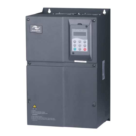
Product Information IS300 Series Servo Drive User Manual Chapter 2 Product Information 2.1 Designation Rules and Nameplate Figure 2-1 Designation rules and nameplate of the IS300 IS300 IS300 series Mark Cooling Mode servo drive Blank Forced air cooling Water cooling... - Page 14 IS300 Series Servo Drive User Manual Product Information Inovance logo Operation panel Front cover Control board Bottom Power cover terminals AC drive nameplate Grommet Item Maximum frequency 300 Hz 0.5–16 kHz Carrier frequency The carrier frequency is automatically adjusted based on the load features.
- Page 15 Product Information IS300 Series Servo Drive User Manual Item Indoor, free from direct sunlight, dust, corrosive Installation location gas, combustible gas, oil smoke, vapour, drip or salt. Lower than 1000 m (de-rated if higher than 1000 Altitude -10°C to +40°C (de-rated if the ambient...
-
Page 16: Chapter 3 Mechanical And Electrical Installation
Mechanical and Electrical Installation efesotomasyon.com... -
Page 17: Mechanical Installation
Cold air installed vertically upward. The IS300 series servo drive dissipates heat from bottom to top. If multiple servo drives are connected together, install them side by side. For the application of installing multiple servo drives, if one row of servo drives need to be installed above another row, install an insulation guide plate to prevent servo drives in the lower row from heating those in the upper row and causing faults. - Page 18 3.1.3 Mechanical Installation Method and Process The IS300 series servo drives have two housing types, plastic housing and sheet metal housing, according to different voltage and power classes. The IS300 supports both wall- mounting installation and embedded installation in different applications.
- Page 19 Mechanical and Electrical Installation IS300 Series Servo Drive User Manual Figure 3-5 Embedded installation of the IS300 (plastic housing) Install the servo drive on the Back panel of front of the control cabinet. control cabinet Figure 3-6 Embedded installation effect of the IS300 (plastic housing) 3.
- Page 20 IS300 Series Servo Drive User Manual Mechanical and Electrical Installation Figure 3-8 Hoisting the IS300 (sheet metal housing) 4. Embedded installation of the IS300 (sheet metal housing) Figure 3-9 External hanging bracket for the IS300 (sheet metal housing) External hanging...
- Page 21 3.1.4 Removal of the Front Cover For the IS300 series servo drives, you need to remove the front cover before wiring the main circuit and control circuit.
-
Page 22: Description And Wiring Of Main Circuit Terminals
IS300 Series Servo Drive User Manual Mechanical and Electrical Installation Figure 3-13 Removal of the front cover of the IS300 (sheet metal housing) 2. Remove the cover toward you. 1. Loosen the four screws. DANGER Be careful when removing the front cover of the servo drive. Falling off of the cover may cause damage to the servo drive or personal injury. -
Page 23: Description And Wiring Of Control Circuit Terminals
Mechanical and Electrical Installation IS300 Series Servo Drive User Manual Terminal Name Description Terminals for connecting Connect to an external reactor for IS300T140-C and P, (+) external reactor above. U, V, W Servo drive output terminals Connect to a three-phase motor. - Page 24 IS300 Series Servo Drive User Manual Mechanical and Electrical Installation Mark Position 1 Function description Position 2 Function description Connect to the terminal Not connect to the terminal matching resistor in the case matching resistor in the case of CAN communication (used...
- Page 25 Mechanical and Electrical Installation IS300 Series Servo Drive User Manual Type Terminal Name Description Analog input 1 Input voltage range: ±10 VDC, 12-bit (pressure AI1-GND resolution, correction accuracy 0.5% reference by default) Analog input 2 Input voltage range: ±10 VDC, 12-bit AI2-GND resolution, correction accuracy 0.5%...
-
Page 26: Description Of Pg Card Terminals On The Is300
IS300 Series Servo Drive User Manual Mechanical and Electrical Installation 3.4 Description of PG Card Terminals on the IS300 Table 3-3 Description of PG card terminals Name Description EXC- Excitation signal EXC+ COS+ COS- SIN+ SIN- SIN feedback signal Blank... -
Page 27: Wiring Of The External Braking Unit
Mechanical and Electrical Installation IS300 Series Servo Drive User Manual Built-in PG card MF38PG4A1 Green Yellow Brown White Blue COS- COS+ SIN- SIN+ EXC- EXC+ Interface for the servo motor control cable Cable for connecting the PG card Model: S3T113CZ-PG 3.5 Wiring of the External Braking Unit... -
Page 28: Wiring Diagram Of System Application
IS300 Series Servo Drive User Manual Mechanical and Electrical Installation Figure 3-19 Basic wiring method 2 Circuit breaker IS300 servo Braking unit drive P(+) Note 1. In this wiring method, the braking unit is connected to COM on one side and DIx on the other side. - Page 29 Mechanical and Electrical Installation IS300 Series Servo Drive User Manual efesotomasyon.com - 28 -...
-
Page 31: Chapter 4 Commissioning And Running Of Servo Pump
Commissioning and Running of Servo Pump efesotomasyon.com... -
Page 32: Use Of The Operation Panel
Commissioning and Running of Servo Pump IS300 Series Servo Drive User Manual Chapter 4 Commissioning and Running of Servo Pump 4. 1 Use of the Operation Panel You can modify the parameters, monitor the working status and start or stop the MD380 by... - Page 33 IS300 Series Servo Drive User Manual Commissioning and Running of Servo Pump TUNE/TC When the indicator is ON, it indicates torque control mode. When the indicator is blinking slowly, it indicates the auto-tuning state. When the indicator is blinking quickly, it indicates the fault state.
- Page 34 Commissioning and Running of Servo Pump IS300 Series Servo Drive User Manual Name Function STOP Stop the servo drive when it is in the running state and perform the Stop/Reset reset operation when it is in the fault state. Quick Enter or exit Level I quick menu.
- Page 35 IS300 Series Servo Drive User Manual Commissioning and Running of Servo Pump In Level III menu, if the parameter has no blinking digit, it means that the parameter cannot Such a function code is only readable, such as, servo drive model, actually detected parameter and running record parameter.
-
Page 36: Application Example
Commissioning and Running of Servo Pump IS300 Series Servo Drive User Manual Figure 4-6 Setting the password Status parameter (Default display) 15.00 ENTER FP-01 FP-00 ENTER 0000 If there is a blinking digit, press to modify the digit. 1234 ENTER... - Page 37 For details on the communication protocols, consult Inovance. 4.2.2 Setting the Running Frequency The IS300 supports two control modes: speed mode and hydraulic mode, set in A3-00. In the speed mode, there are six frequency setting sources, digital setting (UP/DOWN modification, non-retentive at power failure), (UP/DOWN modification, retentive at power failure), AI1, AI2, AI3, and communication setting.
-
Page 38: Servo Pump Commissioning Flowchart
Commissioning and Running of Servo Pump IS300 Series Servo Drive User Manual Figure 4-9 Selecting the frequency source F0-08 Digital setting Retentive at power failure Analog F4-18 to -10 to 10 V F4-22 Analog Speed mode (A3-00 F4-23 to -10 to 10 V... -
Page 39: Motor Trial Running
IS300 Series Servo Drive User Manual Commissioning and Running of Servo Pump Start Control mode: A3-00 4.4.1 Set the command source and control mode Command source: F0-02 Motor parameters: F1-00 to F1-05 4.4.2 Motor Encoder pairs of poles: A1-04 Perform motor auto-tuning... - Page 40 Commissioning and Running of Servo Pump IS300 Series Servo Drive User Manual 4.4.2 Setting and Auto-tuning of Motor Parameters Parameter Setting The IS300 controls the servo pump in closed-loop vector control (CLVC) mode. This mode requires accurate motor parameters. To guarantee good driving performance and running efficiency, set the motor parameters strictly according to the nameplate of the standard adaptable motor.
- Page 41 IS300 Series Servo Drive User Manual Commissioning and Running of Servo Pump Motor Auto-tuning Procedure Figure 4-11 Motor auto-tuning procedure Power on the servo drive. After motor auto-tuning is completed, Set F0-02 to 0 (Operation panel perform trial running: Set F0-08 to control) and F1-00 2 (PMSM).
-
Page 42: Application Commissioning Of Servo Pump
Commissioning and Running of Servo Pump IS300 Series Servo Drive User Manual 4.5 Application Commissioning of Servo Pump 4.5.1 AI Zero Drift Auto Correction Function Step Parameter Description Remarks Code Setting 1. Set the The operation panel command The LOCAL/REMOT indicator is OFF. - Page 43 IS300 Series Servo Drive User Manual Commissioning and Running of Servo Pump F0-02 Command source selection 1: Terminal control Main frequency source X F0-03 selection set F0-03 to 9 (Communication setting). F0-17 Acceleration time1 0.0s F0-18 Deceleration time1 0.0s F1-00...
- Page 44 Commissioning and Running of Servo Pump IS300 Series Servo Drive User Manual Function Parameter Name Description Code It is used to set the minimum hydraulic pressure Corresponding setting of F4-19 reference. The value is 0.0% by default, that is, zero AI1 minimum input pressure.
- Page 45 IS300 Series Servo Drive User Manual Commissioning and Running of Servo Pump Pressure Relief Setting Function Parameter Name Description Code It is used to set the maximum reverse rotational speed at pressure relief. It is a percentage relative to the maximum...
- Page 46 Commissioning and Running of Servo Pump IS300 Series Servo Drive User Manual 4.5.4 Hydraulic PID Response Control Hydraulic PID Mode Selection (A4-05) Function Code Parameter Name Description 1: Auto switchover A4-05 PID control mode 2: PID group determined by DI The IS300 provides four groups of PID, one of which is selected based on the state combinations of DI2 with function 48# and DI3 with function 49#.
- Page 47 IS300 Series Servo Drive User Manual Commissioning and Running of Servo Pump PID Function Condition PID group The hydraulic pressure feedback is larger than the hydraulic pressure A3-14, A3-15, and A3-16 reference by a certain threshold. Overshoot suppression The hydraulic pressure reference is...
- Page 48 Commissioning and Running of Servo Pump IS300 Series Servo Drive User Manual Hydraulic Overshoot Suppression (A3-27 and A3-28) This function is used for pressure overshoot suppression at high speed. A3-27: Overshoot suppression detection level The larger the value of this parameter is, the later the overshoot suppression starts, and the poorer the suppression effect becomes.
-
Page 49: Chapter 5 Troubleshooting
Troubleshooting efesotomasyon.com... -
Page 50: Faults And Solutions
Before contacting Inovance for technical support, you can first determine the fault type, analyze the causes, and perform troubleshooting according to the description in this chapter. - Page 51 IS300 Series Servo Drive User Manual Troubleshooting Err01 (Reserved) Err02 (Overcurrent During Acceleration) Err02 Check whether the servo drive output Eliminate external faults. circuit is earthed or short circuited. V/F control Check whether motor auto-tuning Perform motor auto-tuning. is performed properly.
- Page 52 Troubleshooting IS300 Series Servo Drive User Manual Err04 (Overcurrent at Constant Speed) Err04 Eliminate external faults. Check whether the servo drive output Install an output reactor if circuit is earthed or has leakage current. the cable is too long. Check whether motor auto-tuning Perform motor auto-tuning.
- Page 53 IS300 Series Servo Drive User Manual Troubleshooting Err07 (Overvoltage at Constant Speed) Err07 Check whether the input voltage of Adjust the input voltage to the servo drive is too high. the normal range. Remove the external force Check whether there is an external force or install a braking resistor.
- Page 54 Troubleshooting IS300 Series Servo Drive User Manual Err12 (Phase Loss on Input Side) Err12 Check whether the three-phase Check and eliminate Contact the agent power supply is normal. external faults. or Inovance. Check whether the drive board is normal. Replace the drive board.
- Page 55 IS300 Series Servo Drive User Manual Troubleshooting Err16 (Communication Fault) Err16 Check wiring of the host Check whether the host computer is working. computer. Check whether wiring for RS485 Check wiring of the RS485 communication is normal. communication cable. Check whether communication Set the communication parameters are set properly.
- Page 56 Troubleshooting IS300 Series Servo Drive User Manual Err22 (Reserved) Err23 (Short Circuit to Ground) Err23 Check whether the motor is Replace the cable or motor. short circuited to ground. Replace the servo drive. Err24 to Err42 (Reserved) Err43 (Encoder Fault During Motor Auto-tuning)
-
Page 57: Symptoms And Diagnostics
IS300 Series Servo Drive User Manual Troubleshooting Err46 (Pressure Sensor Fault) Err45 Check whether wiring of the PTC sensor Eliminate the wiring fault. for motor overheat protection is correct. Reduce the load of the Check whether the motor temperature motor, add cooling fans or is too high. - Page 58 Troubleshooting IS300 Series Servo Drive User Manual Symptom Possible Causes Solutions The servo drive display is normal upon power-on, but The cooling fan is damaged or does Replace the cooling fan. it displays "HC" after not rotate. running and stops immediately.
-
Page 59: Chapter 6 Ismg Servo Motor (Voltage Class: 400 V)
ISMG Servo Motor (Voltage Class: 400 V) efesotomasyon.com... -
Page 60: Designation Rules
ISMG Servo Motor IS300 Series Servo Drive User Manual Chapter 6 ISMG Servo Motor (Voltage Class: 400 V) 6.1 Designation Rules ISM G1-30D 15C D-R1 3 1 F Customized Mark Requirement Mark Series No. Natural cooling ISM Series servo motor... -
Page 61: Physical Appearance And Mounting Dimensions Of Ismg Servo Motor
IS300 Series Servo Drive User Manual ISMG Servo Motor 6.2.2 ISMG2 Servo Motor (266 x 266 Base/Forced Air Cooling) See the second table on the last page of this chapter. 6.3 Physical Appearance and Mounting Dimensions of ISMG Servo Motor 6.3.1 ISMG1 Servo Motor (200 x 200 Base/Forced Air Cooling) -
Page 62: Description Of Supporting Board Of Ismg Servo Motor Base
ISMG Servo Motor IS300 Series Servo Drive User Manual 6.3.2 ISMG2 Servo Motor (266 x 266 Base/Forced Air Cooling) Figure 6-2 Physical appearance and mounting dimensions of the ISMG2 servo motor (266 x 266 base/forced air cooling) 0.05 Table 6-2 Mounting dimensions of the ISMG2 servo motor (266 x 266 base/forced air... -
Page 63: Wiring Of Ismg Servo Motor
IS300 Series Servo Drive User Manual ISMG Servo Motor 6.5 Wiring of ISMG Servo Motor 6.5.1 Terminals of PCB Board supply (single-phase 220 V) to the cooling fan. AC1 and AC2 should be wired strictly according to the marks. EXC-... - Page 64 ISMG Servo Motor IS300 Series Servo Drive User Manual efesotomasyon.com - 62 -...
-
Page 66: Chapter 7 Selection And Dimensions
Selection and Dimensions efesotomasyon.com... -
Page 67: Technical Data Of The Is300
Selection and Dimensions IS300 Series Servo Drive User Manual Chapter 7 Selection and Dimensions 7.1 Technical Data of the IS300 Table 7-1 Technical data of the IS300 Adapted Motor (S1) Power Capacity Input Output IS300 Model (kVA) Current (A) Current (A) Single-phase power: 220–230 V, 50/60 Hz... - Page 68 IS300 Series Servo Drive User Manual Selection and Dimensions Adapted Motor (S1) Power Capacity Input Output IS300 Model (kVA) Current (A) Current (A) IS300T004-C IS300T005-C 10.5 IS300T010-C 14.6 IS300T015-C 20.5 IS300T020-C IS300T030-C IS300T035K-C IS300T035-C 38.5 18.5 IS300T040-C 46.5 IS300T050-C IS300T070K-C...
- Page 69 Selection and Dimensions IS300 Series Servo Drive User Manual Adapted Motor (S1) Power Capacity Input Output IS300 Model (kVA) Current (A) Current (A) IS300-5T004-C IS300-5T005-C 10.5 IS300-5T010-C 14.6 IS300-5T015-C 20.5 IS300-5T020-C IS300-5T030-C IS300-5T035-C 38.5 18.5 IS300-5T040-C 46.5 IS300-5T050-C IS300-5T070-C IS300-5T080-C...
-
Page 70: Selection Of Braking Unit And Braking Resistor
IS300 Series Servo Drive User Manual Selection and Dimensions 7.2 Selection of Braking Unit and Braking Resistor Recommended Recommended IS300 Model Power of Braking Braking Unit Remarks Resistance Resistor Single-phase 220–230 V IS300S002-C 80 W IS300S003-C 80 W Built-in IS300S004-C... - Page 71 Selection and Dimensions IS300 Series Servo Drive User Manual Recommended Recommended IS300 Model Power of Braking Braking Unit Remarks Resistance Resistor IS300T030-C 1000 W IS300T035K-C 1300 W IS300T035-C 1300 W Built-in IS300T040-C 1500 W IS300T050-C 2500 W IS300T070K-C 3.7 kW IS300T070-C 3.7 kW...
- Page 72 IS300 Series Servo Drive User Manual Selection and Dimensions Recommended Recommended IS300 Model Power of Braking Braking Unit Remarks Resistance Resistor IS300-5T030-C 1000 W IS300-5T035-C 1300 W Built-in IS300-5T040-C 1500 W IS300-5T050-C 2500 W IS300-5T070-C 3.7 kW External MDBUN-45-5T IS300-5T080-C 4.5 kW...
-
Page 73: Selection Of Peripheral Electrical Devices
Selection and Dimensions IS300 Series Servo Drive User Manual 7.3 Selection of Peripheral Electrical Devices MCCB Contactor I/O Power Cable Cable of Control Circuit IS300 Model Single-phase 220–230 V IS300S002-C 0.75 0.50 IS300S003-C 0.75 0.50 IS300S004-C 0.50 IS300S005-C 0.50 Three-phase 220 V IS300-2T002-C 0.75... - Page 74 IS300 Series Servo Drive User Manual Selection and Dimensions MCCB Contactor I/O Power Cable Cable of Control Circuit IS300 Model IS300T030-C 0.75 IS300T035K-C 1.00 IS300T035-C 1.00 IS300T040-C 1.00 IS300T050-C 1.00 IS300T070K-C 1.00 IS300T070-C 1.00 IS300T080-C 1.00 IS300T100-C 1.00 IS300T140K-C 1.00 IS300T140-C 1.00...
- Page 75 Selection and Dimensions IS300 Series Servo Drive User Manual MCCB Contactor I/O Power Cable Cable of Control Circuit IS300 Model IS300T210-C-L 1.00 IS300T250-C-L 1.00 IS300T300-C-L 1.00 Three-phase 480 V IS300-5T002-C 0.75 0.50 IS300-5T003-C 0.75 0.50 IS300-5T004-C 0.75 0.50 IS300-5T005-C 0.75 IS300-5T010-C 0.75...
-
Page 76: Mounting Dimensions Of The Is300
IS300 Series Servo Drive User Manual Selection and Dimensions Note The models in grey are customized (servo drive of water cooling). 7.4 Mounting Dimensions of the IS300 Figure 7-1 Mounting dimensions of IS300(*)002-C to IS300(*)030-C B H1 Figure 7-2 Mounting dimensions of IS300(*)035-C to IS300(*)720-C efesotomasyon.com... - Page 77 Selection and Dimensions IS300 Series Servo Drive User Manual Table 7-2 Mounting dimensions of IS300 Mounting Hole Mounting Dimensions Mounting Hole Weight (mm) (mm) IS300 Model Diameter (kg) (mm) Single-phase 220–230 V IS300S002-C IS300S003-C IS300S004-C IS300S005-C Three-phase 220 V IS300-2T002-C...
- Page 78 IS300 Series Servo Drive User Manual Selection and Dimensions Mounting Hole Mounting Dimensions Mounting Hole Weight (mm) (mm) IS300 Model Diameter (kg) (mm) IS300T035-C IS300T040-C IS300T050-C IS300T070-C IS300T080-C IS300T100-C IS300T140K-C IS300T140-C IS300T170-C IS300T210-C IS300T250-C IS300T300-C IS300T370-C IS300T420-C 1030 1060 IS300T460-C...
-
Page 79: Physical Appearance And Mounting Of Models With Water Cooling
Selection and Dimensions IS300 Series Servo Drive User Manual Mounting Hole Mounting Dimensions Mounting Hole Weight (mm) (mm) IS300 Model Diameter (kg) (mm) IS300-5T140-C IS300-5T170-C IS300-5T210-C IS300-5T250-C IS300-5T300-C IS300-5T370-C IS300-5T420-C 1030 1060 IS300-5T460-C IS300-5T520-C IS300-5T580-C IS300-5T650-C 1300 1203 1358 IS300-5T720-C 7.5 Physical Appearance and Mounting of Models with Water Cooling... -
Page 80: Mounting Dimensions Of Optional Parts
IS300 Series Servo Drive User Manual Selection and Dimensions Figure 7-4 Physical appearance and mounting dimensions of IS300(*)210-C-L, IS300(*)250- C-L, and IS300(*)300-C-L 281.5 284.8 698.5 1/2 pipe 272.5 thread 7.6 Mounting Dimensions of Optional Parts 7.6.1 External DC Reactor packed and delivered together with the servo drive. - Page 81 Selection and Dimensions IS300 Series Servo Drive User Manual Table 7-3 DC reactor models Diameter of Hole Fixed Reactor IS300 Model for Connecting Hole Model Copper Busbar IS300-2T140-C, IS300-2T170-C IS300T140-C, 160 190 125 161 192 255 195 10 x 15...
- Page 82 IS300 Series Servo Drive User Manual Selection and Dimensions Figure 7-6 Mounting dimensions of the MDBUN-45-X MDBUN series 415 430 braking unit 7.6.3 External Operation Panel Figure 7-7 Mounting dimensions of the external operation panel 76.0 27.0 15.0 54.0 10.0 116.0...
-
Page 83: Servo Motor Code
Selection and Dimensions IS300 Series Servo Drive User Manual 7.7 Servo Motor Code Motor Model Code Motor Model Code Inovance Motor Model Phase Motor Model (FP-02) (FP-02) ISMG1-95C15CD-R131F 00615 U1004F15.3 10415 ISMG1-11D17CD-R131F 00617 U1004F17.3 10417 ISMG1-12D20CD-R131F 00620 U1004F20.3 10420 ISMG1-14D15CD-R131F 00915 U1005F15.3... -
Page 84: Chapter 8 Emc
efesotomasyon.com... -
Page 85: Introduction To Emc Standard
IS300 Series Servo Drive User Manual Chapter 8 EMC Electromagnetic compatibility (EMC) describes the ability of electronic and electrical devices or systems to work properly in the electromagnetic environment and not to In other words, EMC includes two aspects: The electromagnetic interference generated... -
Page 86: Selection Of Peripheral Emc Devices
IS300 Series Servo Drive User Manual 8.2.2 EMC Standard The IS300 series servo drive complies with the following directives and standards. Directive Standard EN 61800-3 EMC directives 2004/18/EC EN 55011 EN 61000-6-2 2006/95/EC LVD directives EN 61800-5-1 93/68/EEC 8.2.3 Installation Environment The system manufacturer using the servo drive is responsible for compliance of the system with the European EMC directives. - Page 87 IS300 Series Servo Drive User Manual IS300 series servo drive. Select a proper one based on actual requirements. Power Capacity Rated Input AC Input Filter Model AC Input Filter Model IS300 Model (kVA) Current (A) (Changzhou Jianli) (Schaffner) Three-phase 380–480 V, 50/60 Hz...
- Page 88 IS300 Series Servo Drive User Manual environment for harmonics. The following table lists the recommended manufacturers and models of input reactors. Table 8-2 Recommended manufacturers and models of AC input reactors Servo Drive Rated Input AC Input Reactor Model Model...
- Page 89 IS300 Series Servo Drive User Manual capacitance enlarges when an over-long cable is used and thus high-harmonics current may be easily generated. If the length of the output cable is equal to or greater than the value in the following table, install an AC output reactor on the power output side of the servo drive.
-
Page 90: Shielded Cable
IS300 Series Servo Drive User Manual Servo Drive Rated Output AC Output Reactor Model Model Current (A) (Inovance) IS300T140K-C MD-OCL-250-4T-114-1% IS300T140-C MD-OCL-330-4T-164-1% IS300T170-C MD-OCL-330-4T-164-1% IS300T210-C MD-OCL-490-4T-224-1% IS300T250-C MD-OCL-490-4T-224-1% IS300T300-C MD-OCL-490-4T-224-1% IS300T370-C MD-OCL-660-4T-304-1% IS300T420-C MD-OCL-660-4T-304-1% IS300T460-C MD-OCL-800-4T-384-1% IS300T520-C MD-OCL-800-4T-384-1% IS300T580-C MD-OCL-5-4T-152-1%... - Page 91 IS300 Series Servo Drive User Manual Figure 8-1 Grounding of the shielded cable The shield must be grounded. The installation precautions are as follows: Symmetrical shielded cable is recommended. The four-conductor shielded cable can also be used as an input cable.
-
Page 92: Solutions To Common Emc Interference Problems
IS300 Series Servo Drive User Manual Figure 8-2 Cabling diagram Power cable Power cable 90° Min. 200 mm Min. 300 mm Motor cable Control cable IS300 servo drive Control cable Braking Min. 500 mm 90° resistor cable Motor cable Control cable Min. - Page 93 IS300 Series Servo Drive User Manual efesotomasyon.com - 90 -...
-
Page 94: Chapter 9 Function Code Table
Function Code Table efesotomasyon.com... - Page 95 Function Code Table IS300 Series Servo Drive User Manual Chapter 9 Function Code Table Function Min. Name Setting Range Default Property Code Unit Group U0: Viewed Servo Drive Parameters 0.00 Hz to maximum U0-00 Running frequency frequency (F0-10) 0.00 Hz to maximum...
- Page 96 IS300 Series Servo Drive User Manual Function Code Table Function Min. Name Setting Range Default Property Code Unit Set hydraulic 0.0 kg to system hydraulic U1-01 pressure pressure (A3-02) 0.0 kg to maximum Feedback hydraulic U1-02 hydraulic pressure (A3- pressure...
- Page 97 Function Code Table IS300 Series Servo Drive User Manual Function Min. Name Setting Range Default Property Code Unit Output phase A0-05 loss PWM 0–63000 detection time Group A1: PG Card Parameters A1-00 to Reserved A1-01 Encoder A1-02 0.0–359.9° 0.1° 0.0°...
- Page 98 IS300 Series Servo Drive User Manual Function Code Table Function Min. Name Setting Range Default Property Code Unit 0.0 kg/cm to maximum System hydraulic 175.0 A3-02 hydraulic pressure (A3- pressure kg/cm kg/cm Maximum hydraulic System hydraulic pressure 250.0 A3-03 pressure (A3-02) to 500.0 kg/cm...
- Page 99 Function Code Table IS300 Series Servo Drive User Manual Function Min. Name Setting Range Default Property Code Unit Setting of maximum A3-22 rotational speed in 0.0%–100.0% 0.1% 10.0% pressure control Setting of minimum A3-23 hydraulic pressure in 0.0%–100.0% 0.1% 60.0%...
- Page 100 IS300 Series Servo Drive User Manual Function Code Table Function Min. Name Setting Range Default Property Code Unit Group A4: Hydraulic Control Optimization Parameters Rotational speed A4-00 0–5.000s 0.001s 0.005s A4-01 0–5.000s 0.001s 0.010s 1: Ordinary oil channel A4-02 Pressure relief mode...
- Page 101 Function Code Table IS300 Series Servo Drive User Manual Function Min. Name Setting Range Default Property Code Unit 0: Same direction F0-09 Rotating direction 1: Reverse direction F0-10 Maximum frequency 50.00–300.00 Hz 200.00 Hz 0: Set by F0-12 1: AI1...
- Page 102 IS300 Series Servo Drive User Manual Function Code Table Function Min. Name Setting Range Default Property Code Unit Rated motor 0.00 to maximum Model F1-04 0.01 Hz frequency frequency Dependent Rated motor Model F1-05 0–30000 RPM 1 RPM rotational speed...
- Page 103 Function Code Table IS300 Series Servo Drive User Manual Function Min. Name Setting Range Default Property Code Unit 0: F2-10 1: AI1 2: AI2 Torque upper limit 3: AI3 F2-09 source 4: Reserved 5: Communication setting Analog input range corresponding to F2-10...
- Page 104 IS300 Series Servo Drive User Manual Function Code Table Function Min. Name Setting Range Default Property Code Unit Group F4: Input Terminals 0: No function 1: Forward RUN (FWD, pump enabled) F4-00 DI1 function selection 2: Reverse RUN (REV) 3: Three-line control...
- Page 105 Function Code Table IS300 Series Servo Drive User Manual Function Min. Name Setting Range Default Property Code Unit Corresponding F4-21 setting of AI1 -100.0%–+100.0% 0.1% 100.0% maximum input F4-22 0.000–10.000s 0.001s 0.010s F4-23 AI2 minimum input -11.00–+11.00 V 0.01 V 0.02 V...
- Page 106 IS300 Series Servo Drive User Manual Function Code Table Function Min. Name Setting Range Default Property Code Unit AI3 corrected voltage F4-52 -9.999–+9.999 V 0.001 V 2.000 V AI3 sampling voltage F4-53 -9.999–+9.999 V 0.001 V 8.000 V AI3 corrected voltage F4-54 -9.999–+9.999 V...
- Page 107 Function Code Table IS300 Series Servo Drive User Manual Function Min. Name Setting Range Default Property Code Unit 0: Running frequency 1: Set frequency 2: Output current F5-10 AO1 output selection 3: Output torque 4: Output power 5: Output voltage...
- Page 108 IS300 Series Servo Drive User Manual Function Code Table Function Min. Name Setting Range Default Property Code Unit Accumulative running F7-09 0–65535 h time F7-10 Software version 1 F7-11 Software version 2 Group F8: Auxiliary Functions F8-00 to Reserved F8-16...
- Page 109 Function Code Table IS300 Series Servo Drive User Manual Function Min. Name Setting Range Default Property Code Unit Motor temperature 0: Disabled F9-16 protection 1: Enabled F9-17 Reserved 0: No fault 1: Reserved 2: Overcurrent during acceleration (Err02) 3: Overcurrent during...
- Page 110 IS300 Series Servo Drive User Manual Function Code Table Function Min. Name Setting Range Default Property Code Unit 42: CAN communication interrupted (Err42) 43: Encoder fault during motor auto-tuning (Err43) 44: Speed deviation too large (Err44) 45: Motor overheat (Err45)
- Page 111 Function Code Table IS300 Series Servo Drive User Manual Function Min. Name Setting Range Default Property Code Unit Accumulative FA-08 business running 0–65535 h time (hour) Accumulative FA-09 business running 0–65535s time (second) A maximum of 4-segment timed running is supported. The relationship among these segments of timed running is: FA-01 <...
- Page 112 IS300 Series Servo Drive User Manual Function Code Table Function Min. Name Setting Range Default Property Code Unit Corresponding setting of multi-point FC-10 -100.0%–+100.0% 0.1% 40.0% input Multi-point AI1 FC-11 -11.00–+11.00 V 0.01 V 5.00 V Corresponding setting of multi-point FC-12 -100.0%–+100.0%...
- Page 113 Function Code Table IS300 Series Servo Drive User Manual Function Min. Name Setting Range Default Property Code Unit Corresponding setting of multi-point FC-24 -100.0%–+100.0% 0.1% 100.0% input Multi-point AI1 FC-25 -11.00–+11.00 V 0.01 V 10.00 V input Corresponding setting of multi-point FC-26 -100.0%–+100.0%...
- Page 114 IS300 Series Servo Drive User Manual Function Code Table Function Min. Name Setting Range Default Property Code Unit Multi-point AI1 FC-37 -11.00–+11.00 V 0.01 V 10.00 V maximum input Corresponding FC-38 setting of multi-point -100.0%–+100.0% 0.1% 100.0% AI1 maximum input...
- Page 115 Function Code Table IS300 Series Servo Drive User Manual Function Min. Name Setting Range Default Property Code Unit Corresponding setting of multi-point FC-52 -100.0%–+100.0% 0.1% 60.0% input Multi-point AI2 FC-53 -11.00–+11.00 V 0.01 V 7.00 V Corresponding setting of multi-point FC-54 -100.0–+100.0%...
- Page 116 IS300 Series Servo Drive User Manual Function Code Table Function Min. Name Setting Range Default Property Code Unit FD-03 Response delay 0–20 ms 2 ms 0.0s: Invalid FD-04 Timeout duration 0.1s 0.0s 0.1–60.0s 0: Standard Modbus protocol, used for host...
- Page 117 Function Code Table IS300 Series Servo Drive User Manual efesotomasyon.com - 114 -...
- Page 118 5. The Product Warranty Card is not re-issued. Please keep the card and present it to the maintenance personnel when asking for maintenance. 6. If there is any problem during the service, contact Inovance’s agent or Inovance directly. 7. This agreement shall be interpreted by Shenzhen Inovance Technology Co., Ltd.
- Page 119 Product Warranty Card Company address: Customer information Contact person: Company name: P.C.: Tel.: Product model: Product Product barcode (Attach here): information Name of agent: (Maintenance time and content): Failure information Maintenance personnel: efesotomasyon.com...
- Page 120 efesotomasyon.com...
Need help?
Do you have a question about the IS300 Series and is the answer not in the manual?
Questions and answers