Inovance IS620P Series User Manual
Hide thumbs
Also See for IS620P Series:
- User manual (223 pages) ,
- Manual (109 pages) ,
- Application manual (221 pages)
Table of Contents
Advertisement
Quick Links
Advertisement
Table of Contents

Related Manuals for Inovance IS620P Series


Summary of Contents for Inovance IS620P Series
- Page 1 efesotomasyon.com...
-
Page 2: Preface
Technology Co., Ltd. The IS620P series is a high-performance AC servo drive for small and medium power applications. The IS620P series ranges from 100 W to 7.5 kW. It supports the Modbus communication protocol with RS232/RS485 communication port, and thus allowing networking of multiple IS620P drives controlled by a host PC. - Page 3 Install an appropriate safety device when this product is to be used on machinery which may cause severe accidents or loss due to trips of the product. Contact Inovance when this product is to be used on special applications such as atomic energy control, aerospace equipment, transport equipment, medical apparatus, safety devices and other equipment that require high cleanliness.
-
Page 4: Table Of Contents
Contents Preface ........................1 Chapter 1 Servo System Selection.................6 1.1 Designation Rules of the Servo Motor and Servo Drive ...........8 ..............9 1.3 Adapted Cables ......................11 ..................13 Chapter 2 Mounting Dimensions of Servo Drive and Servo Motor .......16 2.1 Installation of the Servo Motor ..................16 2.2 Installation of the Servo Drive..................18 2.3 Mounting Dimensions of the Servo Motor ..............20 2.4 Mounting Dimensions of the Servo Drive ...............29... - Page 5 Chapter 7 Function Code Table ................120 Group H00: Servo Motor Parameters .................120 Group H01: Servo Drive Parameters..................122 Group H02: Basic Control Parameters ................122 Group H03: Input Terminal Parameters ................125 Group H04: Output terminal Parameters ................129 Group H05: Position Control Parameters ................132 Group H06: Speed Control Parameters ................137 Group H07: Torque Control Parameters ................139 Group H08: Gain Parameters .....................140...
- Page 6 Servo System Selection efesotomasyon.com...
-
Page 7: Chapter 1 Servo System Selection
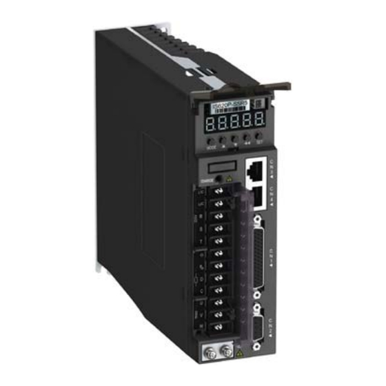
Chapter 1 Servo System Selection IS620P User Manual Chapter 1 Servo System Selection Figure 1-1 Servo drive composition Name Function Connect to the measuring instrument such as an oscilloscope to CN5 analog monitoring signal terminal facilitate viewing signal status when gains are adjusted. Connect to the measuring instrument such as an oscilloscope to LED display facilitate viewing signal status when gains are adjusted. - Page 8 IS620P User Manual Chapter 1 Servo System Selection Figure 1-2 Wiring of single-phase 220 V system Power supply Single-phase 220 Servo drive analog monitoring cable S5-L-A01-1.0 Molded-case circuit breaker (MCCB) Cut off circuit if overcurrent occurs to the protect power supply line. EMI filter Prevent external noise from power supply line.
-
Page 9: Designation Rules Of The Servo Motor And Servo Drive
Chapter 1 Servo System Selection IS620P User Manual Observe the following precautions during wiring: Note 1: Remove the jumper between terminals and D of the servo drive before connecting a braking resistor. Note 2: CN3 and CN4 are two same communication ports, which can be used at random. Note 3: For the single-phase 220 V servo drive, the main circuit terminals are L1 and L2. - Page 10 IS620P User Manual Chapter 1 Servo System Selection Figure 1-4 Designation rules of the servo drive IS620 P S 5R5 I Mark Series Mark Mounting Method IS620 Servo drive Substrate installation standard Mark Product Type Mark Pulse Rated Output 1.6 A 2.8 A 3.5 A 5.4 A...
- Page 11 Chapter 1 Servo System Selection IS620P User Manual 380 V Servo Drive Model Rated Max. Rated Motor Servo Motor Model Drive Drive SN Speed Speed Power Frame Size Three-phase 380 Size 6000 1000 10C30CD T5R4 10002 1500 15C30CD T5R4 10002 2000 20C30CD T8R4...
-
Page 12: Adapted Cables
IS620P User Manual Chapter 1 Servo System Selection 1.3 Adapted Cables Table 1-1 Adapted cables for servo motor Servo Motor Main Circuit Servo Motor Encoder Cable Connector Kit Cable Servo Motor Motor L = 3.0 L = 5.0 L = 10.0 L = 3.0 L = 5.0 L = 10.0... - Page 13 Chapter 1 Servo System Selection IS620P User Manual Table 1-3 Physical appearance of cables for the servo motor and servo drive Cable Cable Name Cable Model Length Cable Appearance S5-L-M03-3.0 3000 100±5 mm S5-L-M03-5.0 5000 25±5 mm 100±5 mm L±30 mm S5-L-M03-10.0 10000 S6-L-M11-3.0 3000...
- Page 14 220 V IS620PS7R6I Three-phase 220 V IS620PS012I IS620PT3R5I IS620PT5R4I IS620PT8R4I Three-phase IS620PT012I 380 V IS620PT017I IS620PT021I IS620PT026I Use an external braking resistor if necessary. For selecting proper external braking resistors, contact Inovance for technical support. efesotomasyon.com - 13 -...
- Page 15 Chapter 1 Servo System Selection IS620P User Manual efesotomasyon.com - 14 -...
- Page 16 Mounting Dimensions efesotomasyon.com...
-
Page 17: Chapter 2 Mounting Dimensions Of Servo Drive And Servo Motor
Chapter 2 Mounting Dimensions of Servo Drive and Servo Motor IS620P User Manual Chapter 2 Mounting Dimensions of Servo Drive and Servo Motor 2.1 Installation of the Servo Motor 2.1.1 Installation Location acid, soda and salt. 2. Select and use the servo motor with oil seal when the motor is to be used in a place with 3. - Page 18 IS620P User Manual Chapter 2 Mounting Dimensions of Servo Drive and Servo Motor 2.1.3 Installation Precautions Table 2-2 Installation precautions Item Description Rust-proof Wipe up the antirust agent at the motor shaft end before installing the servo treatment motor, and then take rust-proof treatment. Do not strike the shaft end during installation.
-
Page 19: Installation Of The Servo Drive
Chapter 2 Mounting Dimensions of Servo Drive and Servo Motor IS620P User Manual Item Description exposed to oil drops, select and use a servo motor with an oil seal. Observe the following conditions when using the servo motor with oil seal: Keep the oil level under the oil seal lip during usage. - Page 20 IS620P User Manual Chapter 2 Mounting Dimensions of Servo Drive and Servo Motor 2.2.2 Installation Environment Table 2-3 Installation environment Item Description Ambient temperature Environment humidity Storage temperature Storage humidity Vibration < 4.9 m/s Shock < 19.6 m/s IP level IP10 Altitude <...
-
Page 21: Mounting Dimensions Of The Servo Motor
Chapter 2 Mounting Dimensions of Servo Drive and Servo Motor IS620P User Manual Install the servo drive vertical to the wall, making its front panel faces outward. 2. Cooling ensure cooling by cooling fans or natural convection. Install cooling fans above the servo drive to avoid excessive temperature rise and maintain even temperature inside the control cabinet. - Page 22 IS620P User Manual Chapter 2 Mounting Dimensions of Servo Drive and Servo Motor -0.1 -0.014 Flat key Shaft end Connector Power Side Brake Side Encoder Side Plastic housing AMP 172165-1 AMP 172169-1 Terminal AMP 770834-1 AMP 770834-1 Servo Motor Model ISMH1-10B30CB-***** M3 x 6 0.06 A...
- Page 23 Chapter 2 Mounting Dimensions of Servo Drive and Servo Motor IS620P User Manual Connector Power Side Brake Side Encoder Side Plastic housing AMP 172165-1 AMP 172169-1 Terminal AMP 770834-1 AMP 770834-1 Servo Motor Model ISMH1-20B30CB-***** M5 x 8 ISMH1-40B30CB-***** 0.06 A 0.02 A 4 x 7 15.5...
- Page 24 IS620P User Manual Chapter 2 Mounting Dimensions of Servo Drive and Servo Motor 2.3.2 Mounting Dimensions of the ISMH2 Series Servo Motor (Vn = 3000 RPM, Vmax = 6000/5000 RPM) , 1.5 kW, 2.0 kW, 2.5 kW 0.06 A 37.5 0.02 A -0.2 4 x R10...
- Page 25 Chapter 2 Mounting Dimensions of Servo Drive and Servo Motor IS620P User Manual 0.10 A 56.5 0.02 A -0.2 4 x R15 -0.09 4 x 9 Shaft end Flat key Connector Power Side Brake Side Encoder Side MIL-DTL-5015 series, MIL-DTL-5015 series, MIL-DTL-5015 series, Aviation plug 3102E20-18P...
- Page 26 IS620P User Manual Chapter 2 Mounting Dimensions of Servo Drive and Servo Motor 2.3.3 Mounting Dimensions of the ISMH3 Series Servo Motor (Vn = 1500 RPM, Vmax = 3000 RPM) 0.10 A 48.5 0.02 A -0.2 4 x R15 -0.09 Shaft end Flat key Connector...
- Page 27 Chapter 2 Mounting Dimensions of Servo Drive and Servo Motor IS620P User Manual 0.10 A 0.03 A 4 x 13.5 4 x R30 -0.09 -0.20 Flat key Shaft end Connector Power Side Brake Side Encoder Side MIL-DTL-5015 series MIL-DTL-5015 series MIL-DTL-5015 series Aviation plug 3102E20-22P...
- Page 28 IS620P User Manual Chapter 2 Mounting Dimensions of Servo Drive and Servo Motor Servo Motor KA1 KA2 KB1 KB2 Weight Model ISMH3- 188 229 20.9 29C15CD- ****Y M12 x -0.036 -0.022 ISMH3- 243 284 29.4 44C15CD- ****Y ISMH3- 271 317 34.5 55C15CD- ****Y...
- Page 29 Chapter 2 Mounting Dimensions of Servo Drive and Servo Motor IS620P User Manual 4 x 5.5 -0.10 -0.018 4 x R5 Shaft end Flat key Connector Power Side Brake Side Encoder Side Plastic housing AMP 172165-1 AMP 172169-1 Terminal AMP 770834-1 AMP 770834-1 Servo Motor Model ISMH4-40B30CB-*****...
-
Page 30: Mounting Dimensions Of The Servo Drive
IS620P User Manual Chapter 2 Mounting Dimensions of Servo Drive and Servo Motor Connector Power Side Brake Side Encoder Side Plastic housing AMP 172165-1 AMP 172169-1 Terminal AMP 770834-1 AMP 770834-1 Servo Motor Model ISMH4-75B30CB-***** M6 x 10 2.4 Mounting Dimensions of the Servo Drive SIZE A: IS620PS1R6I, IS620PS2R8I, IS620PS5R5I SIZE C: IS620PS7R6I, IS620PS012I, IS620PT3R5I, IS620PT5R4I, IS620PT8R4I, IS620PT012I... - Page 31 Chapter 2 Mounting Dimensions of Servo Drive and Servo Motor IS620P User Manual efesotomasyon.com - 30 -...
- Page 32 Wiring of Servo Drive and Servo Motor efesotomasyon.com...
-
Page 33: Chapter 3 Wiring Of Servo Drive And Servo Motor
Chapter 3 Wiring of Servo Drive and Servo Motor IS620P User Manual Chapter 3 Wiring of Servo Drive and Servo Motor Figure 3-1 Terminal pin arrangement of the servo drive DO4+ +24V DO3- CANH DO3+ CANL GNDG DO2- RS485+ PULLHI DO2+ RS485- PAO+... -
Page 34: Servo Drive Main Circuit Wiring
IS620P User Manual Chapter 3 Wiring of Servo Drive and Servo Motor 3.1 Servo Drive Main Circuit Wiring 3.1.1 Introduction to the Main Circuit Figure 3-2 Servo drive main circuit wiring example Table 3-1 Names and functions of main circuit terminals Terminal Terminal Terminal Function... - Page 35 Chapter 3 Wiring of Servo Drive and Servo Motor IS620P User Manual Terminal Terminal Terminal Function Symbol Name Common For common DC bus connection when multiple servo drives are used DC bus in parallel. terminal Servo motor U, V, W connection Connect to U, V and W phases of the servo motor.
- Page 36 M3 combination SIZE C 0.4–0.6 0.6–1.2 screw M4 combination SIZE E 0.7–1.0 screw Table 3-2 Rated input and output currents of IS620P series servo drive Servo Drive Model Rated Input Current Rated Output Max. Output S1R6 S2R8 10.1 SIZE A S5R5 16.9...
- Page 37 Chapter 3 Wiring of Servo Drive and Servo Motor IS620P User Manual Table 3-3 Recommended main circuit cable sizes of IS620P series servo drive Servo Drive Model L1C, L2C R, S, T U, V, W 18 AWG 16 AWG 16 AWG...
- Page 38 IS620P User Manual Chapter 3 Wiring of Servo Drive and Servo Motor Servo Drive Model L1C, L2C R, S, T U, V, W TVR 1.25-3 TVR 1.25-3 TVR 1.25-3 TVR 1.25-3 S7R6 TVR 2-4 TVS 1.25-3 TVS 1.25-3 TVS 1.25-3 TVS 1.25-3 TVR 1.25-3 TVR 2-3M...
- Page 39 Chapter 3 Wiring of Servo Drive and Servo Motor IS620P User Manual 3.1.3 Power Supply Wiring Example Figure 3-4 Main circuit wiring of single-phase 220 V servo drive Single-phase 220 VAC IS620P servo drive Noise filter Stop button Main circuit power input button contactors...
- Page 40 IS620P User Manual Chapter 3 Wiring of Servo Drive and Servo Motor Note 1KM: electromagnetic contactor; 1RY: relay; 1D: bypass diode an error. Meanwhile, the fault indicator goes ON. Observe the following precautions when wiring the main circuit: 1. Do not connect the input power cables to the output terminals U, V and W. Failure to comply will cause damage to the servo drive.
- Page 41 Chapter 3 Wiring of Servo Drive and Servo Motor IS620P User Manual 10. Do not frequently turn ON and OFF the power supply. Do not turn power ON or OFF more than once per minute. Since the servo drive contains a capacitor in the power OFF.
-
Page 42: Connecting Servo Motor Encoder Signals
IS620P User Manual Chapter 3 Wiring of Servo Drive and Servo Motor Connector Frame Size of Terminal Pin Layout Appearance Adaptable Motor MIL-DTL-5015 series 3108E20-18S aviation plug New Structure Old Structure Pin No. Signal Pin No. Signal 20-18 aviation plug A H G Brake of positive or... - Page 43 Chapter 3 Wiring of Servo Drive and Servo Motor IS620P User Manual Table 3-8 Connectors of encoder cables on servo drive side Connector Appearance Terminal Pin Layout Pin No. Signal Housing Recommendation: Table 3-9 Connectors of encoder cables at servo motor side Frame Size of Connector Appearance Terminal Pin Layout...
- Page 44 IS620P User Manual Chapter 3 Wiring of Servo Drive and Servo Motor Motor Side DB9 at Servo Drive Side Function Description 9-pin 20-29 Aviation Plug Signal Pin No. Pin No. Pin No. Encoder +5V power ground Housing Shield Observe the following precautions when wiring the encoder: 1.
-
Page 45: Connecting Control Signal Terminals
Chapter 3 Wiring of Servo Drive and Servo Motor IS620P User Manual 3.3 Connecting Control Signal Terminals Figure 3-8 Pin layout of control circuit terminal connectors of servo drive DO4+ +24V DO3- DO3+ DO2- PULLHI DO2+ PAO+ HPULS- DO1- PAO- DO1+ SIGH+ PBO-... - Page 46 IS620P User Manual Chapter 3 Wiring of Servo Drive and Servo Motor Figure 3-9 Wiring examples in speed/position/torque control mode Wiring in speed control mode AI1 20 Analog speed Low-pass filter converter Servo unit Max. forward Low-pass filter analog speed limit Wiring in position control mode 2.4 k...
- Page 47 Chapter 3 Wiring of Servo Drive and Servo Motor IS620P User Manual 3.3.1 DI/DO Signals Table 3-12 DI/DO signal description Default Signal Pin No. Function Description Function P-OT Forward drive forbidden N-OT Reverse drive forbidden INHIBIT Pulse input forbidden ALM-RST S-ON Servo enabled ZCLAMP...
- Page 48 IS620P User Manual Chapter 3 Wiring of Servo Drive and Servo Motor Use 24 V internal Servo drive Servo drive Use 24 V external power supply: Servo drive No using any single power supply: power supply +24V power supply +24V power +24V power supply supply COM+...
- Page 49 Chapter 3 Wiring of Servo Drive and Servo Motor IS620P User Manual Note terminals may be damaged. Servo drive Servo drive 5-24 VDC 5-24 VDC No relay connected Relay DO1+ DO1+ Wrong polarity of flywheel diode DO1- DO1- Servo drive Servo drive 5-24 VDC 5-24 VDC...
- Page 50 IS620P User Manual Chapter 3 Wiring of Servo Drive and Servo Motor Servo drive -10 to 10 V -10 to 10 V 3.3.3 Position Reference Input Signals Table 3-14 Position reference signal description Signal Pin No. Function Description Common reference pulse PULS+ Pulse input status: input mode:...
- Page 51 Chapter 3 Wiring of Servo Drive and Servo Motor IS620P User Manual Common Reference Pulse Input Differential drive mode Servo drive Host computer 2.4 k PULS+ Common pulse position reference: PULS- Max. input frequency: 2.4 k 500 kpps Min. pulse width: 1 us SIGN+ SIGN- are unstable, which will cause:...
- Page 52 IS620P User Manual Chapter 3 Wiring of Servo Drive and Servo Motor Servo drive +24 V power supply 2.4 k PULLHI PULS+ PULS- 2.4 k SIGN+ SIGN- COM- Pin 14 COM- not connected used. OC pulse position reference: Servo drive Max.
- Page 53 Chapter 3 Wiring of Servo Drive and Servo Motor IS620P User Manual -1.5 10mA Value of resistor R1 shall satisfy the following formula: R1+200 Table 3-16 Recommended R1 resistance Power of R1 24 V 0.5 W 12 V 0.5 W 0.5 W Wrong connection 1: The current-limiting resistor is not connected, resulting in burnout of terminals.
- Page 54 IS620P User Manual Chapter 3 Wiring of Servo Drive and Servo Motor Wrong connection 4: Terminals are not correctly connected, resulting in burnout of terminals. Servo drive OC signal not 2.4 k connected to PULLHI specified terminal PULS+ PULS- 2.4 k SIGN+ SIGN- Wrong connection 5: Multiple terminals share the same current-limit resistor, resulting in that...
- Page 55 Chapter 3 Wiring of Servo Drive and Servo Motor IS620P User Manual Make sure the differential input is 5 V. Otherwise, input pulses of the servo drive are unstable, which will cause: When the reference pulse is input, pulse loss occurs. When reference direction is input, the direction will reverse.
- Page 56 IS620P User Manual Chapter 3 Wiring of Servo Drive and Servo Motor Encoder phase Z output circuit outputs OC signals. Normally, the encoder phase Z output circuit provides feedback signals to the host controller. The circuit and the host controller together form a closed-loop position control system.
- Page 57 Chapter 3 Wiring of Servo Drive and Servo Motor IS620P User Manual The connector of the holding brake is of no polarity. You needs to prepare a 24 V external power supply of the brake. Figure 3-10 Wiring of the holding brake Servo drive Motor Three-phase...
- Page 58 IS620P User Manual Chapter 3 Wiring of Servo Drive and Servo Motor Servo drive ON DI input Servo motor ON Brake DO output H02-12 Position/speed /torque reference H02-09 H02-11 Motor speed The description of the brake output time sequence is as follows: before sending commands to the servo drive.
-
Page 59: Communication Signal Wiring
Chapter 3 Wiring of Servo Drive and Servo Motor IS620P User Manual The description of brake output time sequence is as follows: before sending commands to the servo drive. Otherwise, the servo drive does not respond. When the servo drive is OFF, the brake signal is immediately sent out. The servo motor is still ON within the delay time as set in H02-10, to prevent heavy objects from falling due to gravity. - Page 60 IS620P User Manual Chapter 3 Wiring of Servo Drive and Servo Motor Pin No. Description Terminal Pin layout PC-RXD PC receiving end PC-TXD PC sending end Ground Housing PE Shield Figure 3-12 Communication cable appearance Signal Pin No. Signal Pin No. RS232-TXD PC-RXD RS232-RXD...
- Page 61 Chapter 3 Wiring of Servo Drive and Servo Motor IS620P User Manual The recommended cable is as follows: Z-TEK, model: ZE551A, 0.8-m USN extension cable, chip model: FT232 Figure 3-14 Appearance of the communication cable for parallel connection of multiple servo drives Signal Pin No.
-
Page 62: Analog Monitoring Signal Wiring
IS620P User Manual Chapter 3 Wiring of Servo Drive and Servo Motor 3.5 Analog Monitoring Signal Wiring Figure 3-16 Analog monitoring signal terminal Signal Corresponding interface circuit: Analog output: -10 to +10 V Maximum output current: 1 mA Servo drive Single-direction GALV Single-direction... - Page 63 Chapter 3 Wiring of Servo Drive and Servo Motor IS620P User Manual b. Ground to one point only. supply line. 4. To prevent malfunction due to electromagnetic interference, take the following measures: b. Install a surge absorber on the relay, solenoid and electromagnetic contactor coils. c.
- Page 64 IS620P User Manual Chapter 3 Wiring of Servo Drive and Servo Motor To prevent potential magnetic interference, conduct grounding correctly according to the following instructions. Grounding the motor housing Connect the grounding terminal of the servo motor to the PE terminal of the servo drive and ground the PE terminal, to reduce potential magnetic interference.
- Page 65 Chapter 3 Wiring of Servo Drive and Servo Motor IS620P User Manual power power filter filter supply supply share the same grounding cable with other grounding devices. Figure 3-20 Grounding to one point power power filter filter supply supply Servo Servo Servo Servo...
-
Page 66: Precautions Of Using Cables
IS620P User Manual Chapter 3 Wiring of Servo Drive and Servo Motor power Servo supply filter drive Servo drive Shielded layer grounded Grounding 3.7 Precautions of Using Cables 1. Do not bend or apply tensions to cables. The core wire of a signal cable is only 0.2 or 0.3 mm thin. - Page 67 Chapter 3 Wiring of Servo Drive and Servo Motor IS620P User Manual efesotomasyon.com - 66 -...
- Page 68 Running and Commissioning efesotomasyon.com...
-
Page 69: Chapter 4 Running And Commissioning
Chapter 4 Running and Commissioning IS620P User Manual Chapter 4 Running and Commissioning Based on the command modes and running characteristics, the servo drive supports three running modes, position control, speed control, and torque control. In the position control mode, the displacement is determined based on the number of pulses and the speed is determined based on the input pulse frequency. - Page 70 IS620P User Manual Chapter 4 Running and Commissioning The position control mode is the most common mode of the servo drive. The main use procedure is as follows: 1. Connect the power cables of the main circuit and control circuit of the servo drive, motor power cables, and encoder cables correctly.
- Page 71 Chapter 4 Running and Commissioning IS620P User Manual 4.1.1 Wiring of the Position Control Mode Figure 4-2 Wiring of the position control mode mmomode Servo unit Torque limit: 0-10 V Impedance: about 9 k Low-pass filter Analog output: -10 to +10 V Bi-directional converter Maximum output: <...
- Page 72 IS620P User Manual Chapter 4 Running and Commissioning Note The signal cables and power cables must be laid separately with the distance at least above 30 When the signal cable is not long enough and an extension cable needs to be connected, ensure that the shield is connected reliably and the shielding and grounding are reliable.
- Page 73 Chapter 4 Running and Commissioning IS620P User Manual Function Function No. Description Setting Remarks Name Valid: Forward It is recommended Position reference direction that the logic of the FunIN.27 POSDirSel direction Invalid: Reverse corresponding terminal direction be set to edge valid. Reference pulse form Select the reference pulse form by setting H05-15.
- Page 74 IS620P User Manual Chapter 4 Running and Commissioning Function Function Description Setting Remarks Name This function is now actually Valid: Reference used as position reference Pulse input pulse input forbidden forbidden, involving internal and FunIN.13 INHIBIT forbidden Invalid: Reference external position references. pulse input allowed The logic of the corresponding DI must be set to level valid.
- Page 75 Chapter 4 Running and Commissioning IS620P User Manual Function Min. Effective Control Parameter Name Setting Range Default Property Code Unit Time Mode Pulses for one Power-on H05 02 0–1048576 P/Rev 0 P/Rev At stop motor revolution P/Rev again When this parameter is set, the electronic gear ratio is irrelative to H05-07, H05-09, H05-11 and H05-13, and the electronic gear ratio switchover is not supported.
- Page 76 IS620P User Manual Chapter 4 Running and Commissioning Rectangular Position Reference Ladder Position Reference Before filter Position Average filter time Before filter Position Before filter reference 05-06 After filter reference After filter Before filter After filter After filter Time T Time T Average filter time Average filter time...
-
Page 77: Use Of The Speed Control Mode
Chapter 4 Running and Commissioning IS620P User Manual Table 4-3 Output phase pattern Forward Rotation Reverse Rotation Function Parameter Min. Effective Control Setting Range Default Property Code Name Unit Time Mode 0: CCW direction as the Direction of Power-on H02 03 output pulse 1: CW direction as the forward At stop... - Page 78 IS620P User Manual Chapter 4 Running and Commissioning 3. Connect the required DI/DO signals and analog speed references of terminal CN1 according to Figure 4-6. 4. Perform the setting related to the speed control mode. 5. Make the motor rotate at a low speed and ensure that the rotating direction is normal. Then, adjust the gain.
- Page 79 Chapter 4 Running and Commissioning IS620P User Manual Note The signal cables and power cables must be laid separately with the distance at least above 30 When the signal cable is not long enough and an extension cable needs to be connected, ensure that the shield is connected reliably and the shielding and grounding are reliable.
- Page 80 IS620P User Manual Chapter 4 Running and Commissioning Step Operation Remarks Set related parameters of AI2. Adjust AI2 sampling by setting the zero drift, offset, and dead zone. 3000 RPM. Figure 4-7 No-offset AI2 Speed Speed corresponding to +10 V H03-80 V_Ref -10 V...
- Page 81 Chapter 4 Running and Commissioning IS620P User Manual View the set speed reference value in H0B-01. The multi-speed references refer to the 16 groups of speed references and related control multi-speed references can be used in all the three working modes. H06-04, and the speed reference direction is determined based on the DI states.
- Page 82 IS620P User Manual Chapter 4 Running and Commissioning Function Setting Min. Effective Control Parameter Name Default Property Code Range Unit Time Mode Acceleration ramp During H06 05 time of speed 0-65535 ms 1 ms 0 ms Immediate running reference Deceleration ramp During H06 06 time of speed...
- Page 83 Chapter 4 Running and Commissioning IS620P User Manual exceeds the value, the servo drive outputs the value. The maximum motor rotational speed changes with the actual motor parameters. Note When the rotational speed is restricted, the smallest value of H06-07, H06-08, and H06-09 takes 07, the actual forward rotational speed limit is the value of H06-08, and the reverse rotational speed limit is the value of H06-07.
-
Page 84: Use Of The Torque Control Mode
IS620P User Manual Chapter 4 Running and Commissioning 4. Zero clamp function In the speed control mode, if the ZCLAMP function is valid, and the speed reference amplitude is smaller than or equal to the value of H06-15, the servo motor enters the zero clamp state. - Page 85 Chapter 4 Running and Commissioning IS620P User Manual The main use procedure of the torque control mode is as follows: 1. Connect the power cables of the main circuit and control circuit of the servo drive, motor power cables, and encoder cables correctly. After power-on, the keypad of the servo drive displays "rdy", indicating that the wiring is correct.
- Page 86 IS620P User Manual Chapter 4 Running and Commissioning indicates the twisted pair. Note The signal cables and power cables must be laid separately with the distance at least above 30 When the signal cable is not long enough and an extension cable needs to be connected, ensure that the shield is connected reliably and the shielding and grounding are reliable.
- Page 87 Chapter 4 Running and Commissioning IS620P User Manual Function Parameter Min. Effective Control Setting Range Default Property Code Name Unit Time Mode 0: Main torque reference A source Torque 1: Auxiliary torque reference H07 02 reference B source Immediate At stop source 2: A+B 3: A/B switchover...
- Page 88 IS620P User Manual Chapter 4 Running and Commissioning Figure 4-14 No-offset AI1 Torque Torque corresponding to +10 V H03-81 T_Ref -10 V Dead zone +10 V Voltage H03-53 Torque corresponding to -10 V -H03-81 Figure 4-15 After-offset AI2 No-offset torque reference curve After-offset torque reference curve Torque Torque...
- Page 89 Chapter 4 Running and Commissioning IS620P User Manual Table 4-6 Speed limit diagram Without Speed Limit With Speed Limit Rotational Rotational speed Overspeed may cause speed Maximum mechanical damage. rotational The speed speed is limited. Speed limit When the rotational speed is limited, the DO terminal outputs the signal described in the following table.
- Page 90 IS620P User Manual Chapter 4 Running and Commissioning Function Parameter Min. Effective Control Setting Range Default Property Code Name Unit Time Mode Forward speed limit/Speed 3000 During H07 19 0–9000 RPM Immediate limit 1 in torque running control Reverse speed limit/Speed 3000 During...
- Page 91 Chapter 4 Running and Commissioning IS620P User Manual Function Function Description Setting Remarks Name The torque limit source is switched over based on the setting of H07-07. H07-07 = 1: It is Valid: External reverse torque limit enabled recommended Invalid: Internal reverse torque limit enabled that the External H07-07 = 3 and AI limit smaller than external...
-
Page 92: Check Before Running
IS620P User Manual Chapter 4 Running and Commissioning Function Parameter Min. Effective Control Setting Range Default Property Code Name Unit Time Mode Internal 0.0%–300.0% During H07 10 reverse 0.1% 300.0% Immediate running torque limit External 0.0%–300.0% During H07 11 forward 0.1% 300.0% Immediate running torque limit... - Page 93 Chapter 4 Running and Commissioning IS620P User Manual Complete the installation and wiring correctly, and set H00-00, H02-00, DI/DO parameters in groups H03 and H04, electronic gear ratio and reference input mode in group H05. Perform inertia auto-tuning H0D-02, H08-15, H09-05, H09-06, H09-07, and H09-08 Perform automatic gain adjustment by using the rigid table H09-00 = 1...
- Page 94 The inertia auto-tuning may not be maximum speed for inertia auto- supported. Manually set the inertia tuning H09-06 be increased ratio or contact Inovance. onsite? Hold down the SET key until the keypad displays "SAVE", and then the obtained inertia ratio is written to H08-15.
- Page 95 Chapter 4 Running and Commissioning IS620P User Manual Function Min. Effective Control Parameter Name Setting Range Default Property Code Unit Time Mode 0: Positive and negative triangular H09 05 Immediate At stop auto-tuning mode wave mode Maximum speed H09 06 for inertia auto- 100–1000 RPM 1 RPM...
- Page 96 IS620P User Manual Chapter 4 Running and Commissioning Function Parameter Min. Effective Control Setting Range Default Property Code Name Unit Time Mode 0: Disabled, manual adjusting 1: Standard mode, gain parameters automatically Auto- adjusted based on rigidity During H09 00 adjusting table Immediate...
- Page 97 Chapter 4 Running and Commissioning IS620P User Manual 4.5.4 Notch The mechanical system has a certain resonance frequency. If the gain is too high, resonance around the resonance frequency may occur, and a notch can be used to mechanical resonance. Therefore, the gain can be set higher than that without using the notch.
- Page 98 IS620P User Manual Chapter 4 Running and Commissioning Function Parameter Min. Effective Control Setting Range Default Property Code Name Unit Time Mode 0–4 0: Self-adaptive notch not updated Working mode During H09 02 of self-adaptive Immediate running notch 3: Only detect resonance frequency not update parameters 4: Restore parameters...
- Page 99 Chapter 4 Running and Commissioning IS620P User Manual efesotomasyon.com - 98 -...
- Page 100 Background Software efesotomasyon.com...
-
Page 101: Chapter 5 Background Software
IS620P User Manual Chapter 5 Background Software The background software IS-Opera is provided at www.inovance.cn for free download and the servo drive. You can also make the communication cable yourself, and connect the cable according to the instructions in chapter 3. - Page 102 Troubleshooting efesotomasyon.com...
-
Page 103: Chapter 6 Troubleshooting
Chapter 6 Troubleshooting IS620P User Manual Chapter 6 Troubleshooting 6.1 Analysis and Handling of Faults When a fault occurs on the servo drive, the keypad displays "Er.xxx". You can view the of faults. Fault Display and Probable Cause Solution Description Ensure that the power voltage 1. - Page 104 IS620P User Manual Chapter 6 Troubleshooting Fault Display and Probable Cause Solution Description If the servo drive is powered off and powered on again 1. The logic component Replace the servo several times but the fault Er.104 is faulty. drive. persists, it indicates that the servo drive is faulty.
- Page 105 Chapter 6 Troubleshooting IS620P User Manual Fault Display and Probable Cause Solution Description 1. A parameter check Check whether the cable error occurs or no Connect the between the motor and parameter is stored encoder cable the encoder is connected in the serial encoder again.
- Page 106 IS620P User Manual Chapter 6 Troubleshooting Fault Display and Probable Cause Solution Description If the servo drive is powered Er.207 off and powered on again The servo drive is Replace the servo several times but the fault faulty drive. persists, it indicates that the servo drive is faulty.
- Page 107 Chapter 6 Troubleshooting IS620P User Manual Fault Display and Probable Cause Solution Description 1. When the power voltage is 220 VAC Adjust the AC Measure the power voltage detected bus voltage power voltage is higher than 420 V between terminals to within the voltage is higher than the input voltage limit.
- Page 108 IS620P User Manual Chapter 6 Troubleshooting Fault Display and Probable Cause Solution Description 1. When the power voltage is 220 VAC Increase the Measure the power voltage, detected bus voltage power voltage and and check the bus voltage is lower than 220 V replace the power during running.
- Page 109 Chapter 6 Troubleshooting IS620P User Manual Fault Display and Probable Cause Solution Description 1. The control power Ensure that the Measure the voltage supply is instable or control power between L1C and L2C. power failure occurs. supply is stable. Connect the Er.430 2.
- Page 110 IS620P User Manual Chapter 6 Troubleshooting Fault Display and Probable Cause Solution Description 1. Wiring of the Correct the wiring Check wiring of the motor motor and encoder is or replace the and encoder. incorrect or poor. cables. Increase the 2.
- Page 111 Er.650 motor, increase the acceleration/ deceleration time, and reduce the load. Observe whether the fan Contact Inovance 3. The fan is damaged. works during running. to replace the fan. 4. The installation Install the servo direction and clearance Check the installation of the...
- Page 112 Rotate the motor shaft Replace the manually to check whether 4. The encoder is encoder or contact the value of H0B-10 faulty. Inovance for changes slowly within technical support. 0–360°. Ensure that the 1. The AI voltage is too Measure the AI voltage.
- Page 113 Chapter 6 Troubleshooting IS620P User Manual Fault Display and Probable Cause Solution Description Connect the 1. The cable of the Check connection of encoder cable serial encoder breaks the encoder cable to correctly or or is not connected. see whether incorrect replace the cable.
-
Page 114: Analysis And Handling Of Warnings
IS620P User Manual Chapter 6 Troubleshooting Fault Display and Probable Cause Solution Description 1. The input pulse Check the output frequency Change the frequency is higher of the host controller and maximum than the maximum the maximum frequency set frequency. in H0A-09. - Page 115 Chapter 6 Troubleshooting IS620P User Manual Fault Code and Probable Cause Solution Principle Description There is only high- speed searching and 1. The home switch Replace the home no low-speed searching fails. switch. during the operation of returning to home. Check whether the time 2.
- Page 116 IS620P User Manual Chapter 6 Troubleshooting Fault Code and Probable Cause Solution Principle Description 1. The cable of the external braking 1. Check cable wiring Connect the braking resistor is in of the external braking resistor cable poor connection, resistor according to the correctly.
- Page 117 Chapter 6 Troubleshooting IS620P User Manual Fault Code and Probable Cause Solution Principle Description 9. The resistance of Check whether the the braking resistor setting of H02-27 is Set H02-27 correctly. set in H02-27 is consistent with the accumulative incorrect. actual value.
- Page 118 H0A-00 to 0. Check whether CANlink Er.994 communication is normal Update the software A CANlink address by powering off and then or contact Inovance address powering on the servo for technical support. drive several times. efesotomasyon.com - 117 -...
- Page 119 Chapter 6 Troubleshooting IS620P User Manual efesotomasyon.com - 118 -...
- Page 120 Function Code Table efesotomasyon.com...
-
Page 121: Chapter 7 Function Code Table
Chapter 7 Function Code Table IS620P User Manual Chapter 7 Function Code Table Function Code Group Parameters Group H00 Servo motor parameters Group H01 Servo drive parameters Group H02 Basic control parameters Group H03 Input terminal parameters Group H04 Output terminal parameters Group H05 Position control parameters Group H06... - Page 122 At stop constant Tm again Position offset of 0–1073741824 Power-on H00 28 1 P/Rev At stop absolute encoder P/Rev again 0x000: Incremental Encoder type Power-on H00 30 0x013 At stop again 0x013: Inovance 20-bit serial encoder efesotomasyon.com - 121 -...
-
Page 123: Group H01: Servo Drive Parameters
Chapter 7 Function Code Table IS620P User Manual Function Effective Parameter Name Setting Range Min. Unit Default Property Code Time 1–1073741824 1048576 Power-on H00 31 Encoder PPR 1 P/Rev At stop P/Rev P/Rev again Electrical angle Power-on H00 33 0.0–360.0° 0.1°... - Page 124 IS620P User Manual Chapter 7 Function Code Table Function Min. Effective Control Parameter Name Setting Range Default Property Code Unit Time Mode 0: CCW direction as the forward advancing phase Power-on H02 02 Rotating direction 1: CW direction At stop again as the forward rotation mode,...
- Page 125 Chapter 7 Function Code Table IS620P User Manual Function Min. Effective Control Parameter Name Setting Range Default Property Code Unit Time Mode Brake release command delay During H02 09 20–500 ms 1 ms 250 ms Immediate at servo drive running enabled Servo drive disable delay...
-
Page 126: Group H03: Input Terminal Parameters
IS620P User Manual Chapter 7 Function Code Table Function Min. Effective Control Parameter Name Setting Range Default Property Code Unit Time Mode 0: Internal 1: External, natural cooling Dynamic braking 2: External, forced H02 25 Immediate At stop resistor type air cooling 3: No resistor, using only... - Page 127 Chapter 7 Function Code Table IS620P User Manual Function Parameter Min. Effective Control Setting Range Default Property Code Name Unit Time Mode 0–36 0: No function DI1 function During H03 02 1–36: FunIN.1–36 Upon stop selection running Input polarity: 0–4 0: Low level valid 1: High level valid DI1 logic...
- Page 128 IS620P User Manual Chapter 7 Function Code Table Function Parameter Min. Effective Control Setting Range Default Property Code Name Unit Time Mode 0–36 0: No function DI5 function During H03 10 1–36: FunIN.1–36 Upon stop selection running Input polarity: 0–4 0: Low level valid 1: High level valid DI5 logic...
- Page 129 Chapter 7 Function Code Table IS620P User Manual Function Parameter Min. Effective Control Setting Range Default Property Code Name Unit Time Mode 0–36 0: No function DI9 function During H03 18 1–36: FunIN.1–36 Upon stop selection running Input polarity: 0–4 0: Low level valid 1: High level valid DI9 logic...
-
Page 130: Group H04: Output Terminal Parameters
IS620P User Manual Chapter 7 Function Code Table Function Parameter Min. Effective Control Setting Range Default Property Code Name Unit Time Mode Torque 1–8 times of rated H03 81 corresponding 1.00 1.00 Immediate At stop torque to 10 V Group H04: Output terminal Parameters Function Parameter Min. - Page 131 Chapter 7 Function Code Table IS620P User Manual Function Parameter Min. Effective Control Setting Range Default Property Code Name Unit Time Mode 0–20 0: No function During H04 06 function 1–20: FunOUT.1–2 Upon stop running selection Output polarity reverse setting: 0–1 DO4 logic 0: Output low level when During...
- Page 132 IS620P User Manual Chapter 7 Function Code Table Function Parameter Min. Effective Control Setting Range Default Property Code Name Unit Time Mode AO1 signal During H04 50 Immediate selection running 5: Position reference speed 6: Positioning completed completed: 5 V, positioning 8: AI1 voltage 9: AI2 voltage AO1 offset...
-
Page 133: Group H05: Position Control Parameters
Chapter 7 Function Code Table IS620P User Manual Function Parameter Min. Effective Control Setting Range Default Property Code Name Unit Time Mode During H04 55 multiplying -99.99–+99.99 times 0.01 1.00 Immediate running factor Group H05: Position Control Parameters Function Parameter Effective Control Setting Range... - Page 134 IS620P User Manual Chapter 7 Function Code Table Function Parameter Effective Control Setting Range Min. Unit Default Property Code Name Time Mode 0: Direction + pulse, positive logic 1: Direction + pulse, negative logic Reference Power-on H05 15 2: Phase A + phase At stop pulse form again...
- Page 135 Chapter 7 Function Code Table IS620P User Manual Function Parameter Effective Control Setting Range Min. Unit Default Property Code Name Time Mode Amplitude for 1–65535 encoder 1 encoder During H05 21 positioning encoder Immediate unit unit running completed unit Amplitude of 65535 positioning 1–65535 encoder...
- Page 136 IS620P User Manual Chapter 7 Function Code Table Function Parameter Effective Control Setting Range Min. Unit Default Property Code Name Time Mode 0: Forward home return, deceleration position and home as home switches 1: Reverse home return, deceleration position and home as home switches 2: Forward home return, deceleration...
- Page 137 Chapter 7 Function Code Table IS620P User Manual Function Parameter Effective Control Setting Range Min. Unit Default Property Code Name Time Mode Speed of home switch signal During H05 32 0–3000 RPM 1 RPM 100 RPM Immediate at high-speed running searching Speed of home switch signal...
-
Page 138: Group H06: Speed Control Parameters
IS620P User Manual Chapter 7 Function Code Table Function Parameter Effective Control Setting Range Min. Unit Default Property Code Name Time Mode 0: H05-36 as coordinate for home return, trigger home return and after reaching limit switch 1: H05-36 as relative offset for home return, trigger home return and... - Page 139 Chapter 7 Function Code Table IS620P User Manual Function Parameter Min. Effective Control Setting Range Default Property Code Name Unit Time Mode 0: Main speed reference A source 1: Auxiliary speed Speed reference reference B source H06 02 Immediate At stop selection 2: A+B 3: A/B switchover...
-
Page 140: Group H07: Torque Control Parameters
IS620P User Manual Chapter 7 Function Code Table Group H07: Torque Control Parameters 100% of the torque reference corresponds to the rated motor torque. Function Parameter Min. Effective Control Setting Range Default Property Code Name Unit Time Mode Main torque H07 00 reference A 1: AI1... -
Page 141: Group H08: Gain Parameters
Chapter 7 Function Code Table IS620P User Manual Function Parameter Min. Effective Control Setting Range Default Property Code Name Unit Time Mode External 0.0%–300.0% During H07 11 forward torque 0.1% 300.0% Immediate running limit External 0.0%–300.0% During H07 12 reverse torque 0.1% 300.0% Immediate running limit... - Page 142 IS620P User Manual Chapter 7 Function Code Table Function Parameter Min. Effective Control Setting Range Default Property Code Name Unit Time Mode Speed loop 0.01 During H08 01 integral time 0.15–512.00 ms 31.83 ms Immediate running constant Position loop During H08 02 0.0–2000.0 Hz 0.1 Hz 40.0 Hz Immediate...
- Page 143 Chapter 7 Function Code Table IS620P User Manual Function Parameter Min. Effective Control Setting Range Default Property Code Name Unit Time Mode Gain During H08 10 switchover 0.0–1000.0 ms 0.1 ms 5.0 ms Immediate running delay Gain Based During H08 11 switchover 0–20000 Immediate...
-
Page 144: Group H09: Auto-Adjusting Parameters
IS620P User Manual Chapter 7 Function Code Table Group H09: Auto-adjusting Parameters Function Min. Effective Control Parameter Name Setting Range Default Property Code Unit Time Mode 0: Disabled, manual adjusting 1: Standard mode, gain parameters automatically Auto-adjusting adjusted based on During H09 00 Immediate... - Page 145 Chapter 7 Function Code Table IS620P User Manual Function Min. Effective Control Parameter Name Setting Range Default Property Code Unit Time Mode Maximum speed H09 06 for inertia auto- 100–1000 RPM 1 RPM Immediate At stop tuning Acceleration/ Deceleration time H09 07 20–800 ms 1 ms...
-
Page 146: Group H0A: Fault And Protection
IS620P User Manual Chapter 7 Function Code Table Function Min. Effective Control Parameter Name Setting Range Default Property Code Unit Time Mode Disturbance torque During H09 30 -100.0%–+100.0% 0.1% 0.0% Immediate compensation running gain Disturbance During H09 31 0.00–25.00 ms 0.01 ms 0.5 ms Immediate running time... - Page 147 Chapter 7 Function Code Table IS620P User Manual Function Parameter Effective Control Setting Range Min. Unit Default Property Code Name Time Mode H0A 14 Reserved H0A 15 Reserved Position deviation 0.0001 During H0A 16 threshold in 1–1000 Immediate running low-frequency vibration Runaway 0: Disabled...
-
Page 148: Group H0B: Display Parameters
IS620P User Manual Chapter 7 Function Code Table Group H0B: Display Parameters Function Setting Effective Control Parameter Name Min. Unit Default Property Code Range Time Mode Actual motor H0B 00 1 RPM At display rotational speed H0B 01 Speed reference 1 RPM At display Internal torque... - Page 149 Chapter 7 Function Code Table IS620P User Manual Function Setting Effective Control Parameter Name Min. Unit Default Property Code Range Time Mode H0B 26 Bus voltage 0.1 V At display H0B 27 Module temperature 1°C At display H0B 28 Reserved H0B 29 Reserved H0B 30 Reserved H0B 31 Reserved...
-
Page 150: Group H0C: Communication Parameters
IS620P User Manual Chapter 7 Function Code Table Function Setting Effective Control Parameter Name Min. Unit Default Property Code Range Time Mode H0B 49 Reserved H0B 50 Reserved H0B 51 Reserved Reference position 1 reference H0B 53 At display in position control unit Actual motor H0B 55... - Page 151 Chapter 7 Function Code Table IS620P User Manual Function Parameter Min. Effective Control Setting Range Default Property Code Name Unit Time Mode Bit0: VDI1 default value Default virtual …… Power-on During H0C 10 level of VDI at Bit15: VDI16 default again running power-on...
-
Page 152: Group H0D: Auxiliary Function Parameters
IS620P User Manual Chapter 7 Function Code Table Function Parameter Min. Effective Control Setting Range Default Property Code Name Unit Time Mode Sync messages H0C 18 received from display host controller SDO messages H0C 20 received from display host controller PDO messages H0C 22 received from... - Page 153 Chapter 7 Function Code Table IS620P User Manual Function Min. Effective Control Parameter Name Setting Range Default Property Code Unit Time Mode 0: No operation Encoder ROM H0D 04 1: Read ROM Immediate At stop read/write 2: Write ROM 0: No operation During H0D 05 Emergency stop Immediate...
-
Page 154: Group H0F: Full Closed-Loop Parameters
IS620P User Manual Chapter 7 Function Code Table Group H0F: Full Closed-loop Parameters Function Parameter Min. Effective Control Setting Range Default Property Code Name Unit Time Mode 0: Internal encoder feedback 1: External encoder feedback Encoder 2: Internal/External Power-on H0F 00 At stop feedback mode position closed-... -
Page 155: Group H11: Multi-Position Function Parameters
Chapter 7 Function Code Table IS620P User Manual Group H11: Multi-Position Function Parameters Function Effective Control Parameter Name Setting Range Min. Unit Default Property Code Time Mode 0: Stop after a single running selection in 1: Cyclic running selection in Multi-position H11 00 Immediate At stop... - Page 156 IS620P User Manual Chapter 7 Function Code Table Function Effective Control Parameter Name Setting Range Min. Unit Default Property Code Time Mode 0: Relative displacement Displacement reference H11 04 Immediate At stop reference type 1: Absolute displacement reference Start position of H11 05 0–16 Immediate At stop...
- Page 157 Chapter 7 Function Code Table IS620P User Manual Function Effective Control Parameter Name Setting Range Min. Unit Default Property Code Time Mode -1073741824– 10000 During H11 22 3rd displacement +1073741824 reference reference Immediate running reference unit unit unit Maximum During H11 24 running speed of 1–9000 RPM...
- Page 158 IS620P User Manual Chapter 7 Function Code Table Function Effective Control Parameter Name Setting Range Min. Unit Default Property Code Time Mode Acceleration/ Deceleration 0–65535 ms During H11 40 Immediate time of 6th running displacement< Waiting time 0–10000 ms During H11 41 after 6th Immediate...
- Page 159 Chapter 7 Function Code Table IS620P User Manual Function Effective Control Parameter Name Setting Range Min. Unit Default Property Code Time Mode -1073741824– 10000 10th During H11 57 +1073741824 reference reference Immediate displacement running reference unit unit unit Maximum running During H11 59 1–9000 RPM...
- Page 160 IS620P User Manual Chapter 7 Function Code Table Function Effective Control Parameter Name Setting Range Min. Unit Default Property Code Time Mode Maximum running During H11 74 1–9000 RPM 1 RPM 200 RPM Immediate speed of 13th running displacement Acceleration/ Deceleration 0–65535 ms During...
-
Page 161: Group H12: Multi-Speed Function Parameters
Chapter 7 Function Code Table IS620P User Manual Function Effective Control Parameter Name Setting Range Min. Unit Default Property Code Time Mode Acceleration/ Deceleration 0–65535 ms During H11 90 Immediate time of 16th running displacement< Waiting time 0–10000 ms During H11 91 after 16th Immediate... - Page 162 IS620P User Manual Chapter 7 Function Code Table Function Parameter Min. Effective Control Setting Range Default Property Code Name Unit Time Mode Running time 0.1s 5.0s H12 21 of 1st speed Immediate At stop reference 0: No acceleration/ deceleration time 1: Acceleration/ Acceleration/ Deceleration time 1...
- Page 163 Chapter 7 Function Code Table IS620P User Manual Function Parameter Min. Effective Control Setting Range Default Property Code Name Unit Time Mode Running time 0.1s 5.0s H12 30 of 4th speed Immediate At stop reference 0: No acceleration/ deceleration time 1: Acceleration/ Acceleration/ Deceleration time 1...
- Page 164 IS620P User Manual Chapter 7 Function Code Table Function Parameter Min. Effective Control Setting Range Default Property Code Name Unit Time Mode Running time 0.1s 5.0s H12 39 of 7th speed Immediate At stop reference 0: No acceleration/ deceleration time 1: Acceleration/ Acceleration/ Deceleration time 1...
- Page 165 Chapter 7 Function Code Table IS620P User Manual Function Parameter Min. Effective Control Setting Range Default Property Code Name Unit Time Mode Running time 0.1s 5.0s H12 48 of 10th speed Immediate At stop reference 0: No acceleration/ deceleration time 1: Acceleration/ Acceleration/ Deceleration time 1...
- Page 166 IS620P User Manual Chapter 7 Function Code Table Function Parameter Min. Effective Control Setting Range Default Property Code Name Unit Time Mode 0: No acceleration/ deceleration time 1: Acceleration/ Acceleration/ Deceleration time 1 Deceleration 2: Acceleration/ H12 58 Immediate At stop time of 13th Deceleration time 2 speed reference...
-
Page 167: Group H17: Vdi/Vdo Parameters
Chapter 7 Function Code Table IS620P User Manual Function Parameter Min. Effective Control Setting Range Default Property Code Name Unit Time Mode 0: No acceleration/ deceleration time 1: Acceleration/ Acceleration/ Deceleration time 1 Deceleration 2: Acceleration/ H12 67 Immediate At stop time of 16th Deceleration time 2 speed reference... - Page 168 IS620P User Manual Chapter 7 Function Code Table Function Parameter Min. Effective Control Setting Range Default Property Code Name Unit Time Mode 0: Valid when the written value VDI4 logic is 1 Upon During H17 07 selection 1: Valid when the written value stop running changes from 0 to 1...
- Page 169 Chapter 7 Function Code Table IS620P User Manual Function Parameter Min. Effective Control Setting Range Default Property Code Name Unit Time Mode 0: No function VDI10 1–36: FunIN.1–36 Upon During H17 18 function stop running selection 0: Valid when the written value VDI10 logic is 1 Upon...
- Page 170 IS620P User Manual Chapter 7 Function Code Table Function Parameter Min. Effective Control Setting Range Default Property Code Name Unit Time Mode 0: Valid when the written value VDI15 logic is 1 Upon During H17 29 selection 1: Valid when the written value stop running changes from 0 to 1...
- Page 171 Chapter 7 Function Code Table IS620P User Manual Function Parameter Min. Effective Control Setting Range Default Property Code Name Unit Time Mode 0: No function VDO6 1–20: FunOUT.1–20 Upon During H17 43 function stop running selection VDO6 logic 0: Output 1 when valid Upon During H17 44...
-
Page 172: Group H30: Servo State Variables Read By Communication
IS620P User Manual Chapter 7 Function Code Table Function Parameter Min. Effective Control Setting Range Default Property Code Name Unit Time Mode 0: No function VDO13 1–20: FunOUT.1–20 Upon During H17 57 function stop running selection VDO13 logic 0: Output 1 when valid Upon During H17 58... -
Page 173: Group H31: Variables Set Via Communication
Chapter 7 Function Code Table IS620P User Manual Function Min. Effective Control Parameter Name Setting Range Default Property Code Unit Time Mode Input reference H30 03 pulse sampling read display by communication Group H31: Variables Set via Communication The values are not displayed on the keypad. Function Min. - Page 174 IS620P User Manual Chapter 7 Function Code Table Function Function Symbol Description Remarks Name The logic of the corresponding terminal The servo drive can must be set to edge Alarm reset continue to work after valid. FunIN.2 ALM-RST alarms of certain types are If you set the logic to reset.
- Page 175 Chapter 7 Function Code Table IS620P User Manual Function Function Symbol Description Remarks Name Perform switchover between speed control, It is recommended Mode position control, and that the logic of the FunIN.11 M2-SEL switchover torque control based on corresponding terminal M2-SEL the selected control mode be set to edge valid.
- Page 176 IS620P User Manual Chapter 7 Function Code Table Function Function Symbol Description Remarks Name The torque limit source is switched over based on the setting of H07-07. H07-07 = 1: Valid: External forward torque limit enabled Invalid: Internal forward torque limit enabled H07-07 = 3 and AI limit It is recommended External...
- Page 177 Chapter 7 Function Code Table IS620P User Manual Function Function Symbol Description Remarks Name Valid: Execute step It is recommended DI position reference that the logic of the FunIN.20 POSSTEP step Invalid: Reference being corresponding terminal reference zero, in positioning state be set to edge valid.
- Page 178 IS620P User Manual Chapter 7 Function Code Table Function Function Symbol Description Remarks Name The logic of the corresponding terminal must be set to level valid. If you set the logic Home Invalid: Not triggered to 2, the servo drive FunIN.31 HomeSwitch switch...
- Page 179 Chapter 7 Function Code Table IS620P User Manual Function Function Symbol Description Remarks Name Output Function Description The servo drive is in ready state and can receive the Servo drive S-ON signal. FunOUT.1 S-RDY ready Valid: Servo drive ready Invalid: Servo drive not ready When the motor rotational speed exceeds the...
- Page 180 IS620P User Manual Chapter 7 Function Code Table Function Function Symbol Description Remarks Name Brake output: Brake FunOUT.9 Valid: Brake released output Invalid: Brake applied Warning The warning output is FunOUT.10 WARN output This signal is valid when a FunOUT.11 Fault output fault occurs.
-
Page 181: Appendix: Version Change Record
Appendix: Version Change Record Date Version Change Otc. 2013 V0.0 First issue. efesotomasyon.com... - Page 182 5. The Product Warranty Card is not re-issued. Please keep the card and present it to the maintenance personnel when asking for maintenance. 6. If there is any problem during the service, contact Inovance’s agent or Inovance directly. 7. This agreement shall be interpreted by Suzhou Inovance Technology Co., Ltd.
- Page 183 Product Warranty Card Company address: Customer information Contact person: Company name: P.C.: Tel.: Product model: Product information Name of agent: Failure information Maintenance personnel: efesotomasyon.com...
- Page 184 efesotomasyon.com...
Need help?
Do you have a question about the IS620P Series and is the answer not in the manual?
Questions and answers
Alarm parameter bhejiye
The Inovance IS620P Series alarms are graded into four levels based on severity:
1. No.1 non-resettable fault
2. No.1 resettable fault
3. No.2 resettable fault
4. No.3 resettable alarm
"Resettable" means the fault/alarm display stops when a reset signal is input. To reset:
- Set parameter H0D-01 = 1 (fault reset enabled), or
- Set the DI terminal assigned to function FunIN.2 (ALM-RST) to ON.
For No.1 and No.2 faults, also turn off the servo enable signal (S-ON = OFF) before resetting.
Some alarms/faults require fixing the cause and changing parameters. Changes take effect after reconnecting control power (L1C, L2C) or stopping the servo drive.
This answer is automatically generated