turck BL20 Series Manual
Gateway for modbus rtu
Hide thumbs
Also See for BL20 Series:
- Instructions for use manual (537 pages) ,
- User manual (461 pages) ,
- Manual (9 pages)
Table of Contents
Advertisement
Quick Links
Advertisement
Chapters
Table of Contents

Related Manuals for turck BL20 Series


Summary of Contents for turck BL20 Series
- Page 1 BL20 – GATEWAY Modbus RTU Sense it! Connect it! Bus it! Solve it!
- Page 2 No part of this manual may be reproduced in any form (printed, photocopy, microfilm or any other process) or processed, duplicated or distributed by means of electronic systems without written permission of Hans Turck GmbH & Co. KG, Muelheim an der Ruhr. Subject to alterations without notice...
-
Page 3: Table Of Contents
Table of Contents About this manual Documentation concept ..........................1-2 Description of symbols used ..........................1-3 General ................................1-4 1.3.1 Prescribed use ......................................1-4 1.3.2 Notes concerning planning/ installation of this product ......................1-4 BL20-philosophy The basic concept ............................2-2 2.1.1 Flexibility ........................................2-2 2.1.2 Compactness ......................................2-2 2.1.3 Easy to handle ......................................2-2 BL20 components ............................2-3... - Page 4 Implementation of Modbus TCP Common Modbus description ........................4-2 4.1.1 Protocol description ..................................... 4-3 4.1.2 Data model....................................... 4-4 Implemented Modbus functions ........................4-6 Modbus registers ............................4-7 Structure of the packed in-/ output process data ..................4-12 4.4.1 Packed input process data ................................4-13 4.4.2 Packed output process data ................................4-13 Data width of the I/O-modules in the modbus-register area ..............
- Page 5 5.3.8 CoDeSys: Global variables................................5-17 5.3.9 Modbus channels ....................................5-18 5.3.10 Building, login and start..................................5-30 5.3.11 Reading out the process data ................................. 5-31 5.3.12 Diagnosis evaluation..................................5-32 Guidelines for station planning Module arrangement ............................6-2 6.1.1 Random module arrangement................................6-2 6.1.2 Complete planning....................................6-3 6.1.3 Maximum system extension ................................6-3...
- Page 6 Appendix Data image of the technology modules......................9-2 9.1.1 1RS232/ 1RS485-module..................................9-2 9.1.2 SSI module........................................ 9-6 9.1.3 SWIRE-module ......................................9-13 9.1.4 Encoder/PWM-module: BL20-E-2CNT-2PWM..........................9-15 9.1.5 RFID-module: BL20-2RFID-S................................9-15 Ident codes the BL20-modules........................9-16 Index D301295 0513 - BL20 - Modbus RTU...
-
Page 7: About This Manual
About this manual Documentation concept ..........................2 Description of symbols used ........................3 General ................................4 1.3.1 Prescribed use .......................................4 1.3.2 Notes concerning planning/ installation of this product ......................4 D301295 0513 - BL20 - Modbus RTU... -
Page 8: Documentation Concept
The bus-independent I/O-modules of the BL20-system as well as all bus independent information as mounting, labeling etc. are described in a separate manual. BL20 I/O-modules (TURCK-documentation no.: German D300716; English D300717) In addition to that, the manual contains a short description of the I/O-ASSISTANT, the project planning... -
Page 9: Description Of Symbols Used
Description of symbols used Description of symbols used Warning This sign can be found next to all notes that indicate a source of hazards. This can refer to danger to personnel or damage to the system (hardware and software) and to the facility. This sign means for the operator: work with extreme caution. -
Page 10: General
About this manual General Attention Please read this section carefully. Safety aspects cannot be left to chance when dealing with electrical equipment. This manual includes all information necessary for the prescribed use of the BL20-E-GW-RS-MB/ET. It has been specially conceived for personnel with the necessary qualifications. 1.3.1 Prescribed use Appropriate transport, storage, deployment and mounting as well as careful operating and thorough... -
Page 11: Bl20-Philosophy
BL20-philosophy The basic concept ............................2 2.1.1 Flexibility .........................................2 2.1.2 Compactness ......................................2 2.1.3 Easy to handle .......................................2 BL20 components............................3 2.2.1 Gateways .........................................3 – ECO-gateways ....................................3 – Gateways with integrated power supply ..........................4 – Gateways without integrated power supply .........................4 2.2.2 Power distribution modules................................4 2.2.3... -
Page 12: The Basic Concept
BL20-philosophy The basic concept BL20 is a modular I/O system for use in industrial automation. It connects the sensors and actuators in the field with the higher-level master. BL20 offers modules for practically all applications: Digital input and output modules Analog input and output modules Technology modules (counters, RS232 interface...) A complete BL20 station counts as one station on the bus and therefore occupies one fieldbus address... -
Page 13: Bl20 Components
The gateway connects the fieldbus to the I/O modules. It is responsible for handling the entire process data and generates diagnostic information for the higher-level master and the software tool PACTware with the respective TURCK-DTMs (I/O-ASSISTANT). ECO-gateways The BL20-ECO gateways enlarge the product portfolio of BL20. They offer an excellent cost/ performance ratio. -
Page 14: Power Distribution Modules
BL20-philosophy Gateways with integrated power supply All actual BL20-gateways provide an integrated power supply unit for supplying the gateway and the connected modules. It is not necessary to supply the station using a special supply module with a separate voltage. Gateways without integrated power supply Note The gateways without integrated power supply unit need an additional power supply... -
Page 15: Electronics Modules (Standard Product Line)
BL20 components 2.2.3 Electronics modules (standard product line) The standard electronics modules contain the I/O-functions of the BL20 modules (power distribution modules, digital and analog input/output modules, and technology modules). They are plugged onto the base modules and are not directly connected to the wiring and can be plugged or pulled when the station is being commissioned or for maintenance purposes, without having to disconnect the field wiring from the base modules. -
Page 16: Eco Electronics Modules
BL20-philosophy 2.2.4 ECO electronics modules New ECONOMY modules with a high signal density and exceptionally low channel price expand the BL20 I/O bus terminal system. Depending on type, up to 16 digital inputs and outputs can be connected on only 13 mm. This high connection density considerably reduces the mounting width required for typical applications. -
Page 17: Base Modules
BL20 components 2.2.5 Base modules The field wiring is connected to the base modules. These are constructed as terminals in block and slice designs and are available in the following variations with either tension clamp or screw connections: 2- /3-wire (2-channel), 4-wire (2-channel) and 4x2-/3-wire (4-channel). Figure 2-5: Base module with tension... -
Page 18: End Plate
BL20-philosophy 2.2.6 End plate An end plate on the right-hand side physically completes the BL20 station. An end bracket mounted into the end plate ensures that the BL20 station remains secure on the mounting rail even when subjected to vibration. Figure 2-8: End plate 2.2.7... -
Page 19: Jumpers
BL20 components 2.2.8 Jumpers Jumpers (QVRs) are used to bridge a connection level of a 4-wire base module. They can be used to connect potentials in relay modules (bridging the relay roots); thus considerably reducing the amount of wiring. Figure 2-10: Jumpers Labels: for labeling BL20 electronics modules. -
Page 20: Shield Connection Gateway
BL20-philosophy 2.2.9 Shield connection gateway If the gateway is wired directly to the fieldbus, it is possible to shield the connection using a special gateway-shielding connection attachment (BS3511/KLBUE4-31.5). Figure 2-12: Shield connec- tion (gateway) 2-10 D301295 0513 - BL20 - Modbus RTU... -
Page 21: Technical Features
Technical features Introduction..............................2 Function ................................. 3 Technical data..............................4 3.3.1 Block diagram......................................5 3.3.2 General technical data of a station ...............................5 – Approvals and tests..................................7 3.3.3 Technical data for the push-in tension clamp terminals ......................8 Connection options at the gateway......................9 3.4.1 Power supply ......................................9 3.4.2... -
Page 22: Introduction
Technical features Introduction This chapter contains the technical description of the BL20-gateway for serial Modbus (RTU/ASCII). The chapter contains: the technical data, the connection options, the description of address assignment etc.. D301295 0513 - BL20 - Modbus RTU... -
Page 23: Function
Function Function BL20-gateways are used to connect BL20 I/O modules to the Modbus-network. The gateway handles the entire process data exchange between the I/O-level and the fieldbus and generates diagnostic information for higher-level nodes and the software tool I/O-ASSISTANT. D301295 0513 - BL20 - Modbus RTU... -
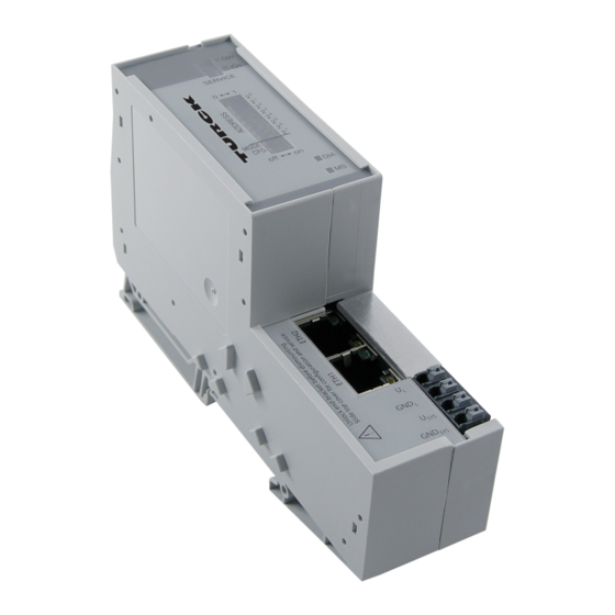
Page 24: Technical Data
Technical features Technical data Figure 3-1: Front view BL20-E-GW-RS-MB/ET A LEDs for BL20 module bus B service interface SERVICE C DIP-switch for node address D DIP-switch for bit rate E DIP-switch for interface selec- tion F DIP-switch for terminating RS485 RS232 resistor G DIP-switch for... -
Page 25: Block Diagram
Technical data 3.3.1 Block diagram Figure 3-2: Service Block diagram BL20-E-GW-RS- MB/ET Module bus RS232/RS485 24 V Tx / A Rx / B 3.3.2 General technical data of a station Attention The auxiliary power supply must comply with the stipulations of SELV (Safety Extra Low Voltage) according to IEC 364-4-41. - Page 26 Technical features Data bits 7 or 8 Parity none, even, odd Address setting 1-31 (DIP-switches at the gateway, 2 to 2 1...-127 (via DTM) service interface mini USB Isolation voltages 500 V (supply voltage against Ethernet) (system / RS485) (system / RS232) Ambient conditions Ambient temperature –...
-
Page 27: Approvals And Tests
Technical data Electromagnetic compatibility (EMC) according to EN 50 082-2 (Industry) Static electricity according to EN 61 000-4-2 – Discharge through air (direct) 8 kV – Relay discharge (indirect) 4 kV Electromagnetic HF fields according to 10 V/m EN 61 000-4-3 and EN 50 204 A Using the device Conducted interferences induced by HF 10 V... -
Page 28: Technical Data For The Push-In Tension Clamp Terminals
Technical features 3.3.3 Technical data for the push-in tension clamp terminals Table 3-3: Designation Technical data Protection class IP20 Push-in tension clamp terminals Insulation stripping length 8 mm + 1/ 0.32 inch + 0,039 Max. wire range 0.14 to 1.5 mm / 0.0002 to 0.0023 inch / 26 to 16 Crimpable wire... -
Page 29: Connection Options At The Gateway
Connection options at the gateway Connection options at the gateway The field bus as well as the power supply are connected to the gateway using push-in tension clamp terminals. Figure 3-3: Connection options at the GND L gateway U SYS GND SYS Tx / A Rx / B... -
Page 30: Fieldbus Connection
Technical features 3.4.2 Fieldbus connection Table 3-4: BL20-E-GW-RS-MB/ET other Field bus adata end device connection terminal connection - connection RS232-connection assignment Rx / B Tx / A RS485-connection Tx / A Rx/Tx+ (A) 120 120 Rx / B Rx/Tx- (B) 3-10 D301295 0513 - BL20 - Modbus RTU... -
Page 31: Service Interface Connection (Mini Usb Female Connector)
Connection options at the gateway 3.4.3 Service interface connection (mini USB female connector) The service interface is used to connect the gateway to the project planning and diagnostic software I/O-ASSISTANT (FDT/DTM). The service interface is designed as a 5 pole mini-USB-connection. In order to connect the gateway’s service-interface to the PC, a commercial cable with mini USB connector (commonly used for e.g. -
Page 32: Configuration Of The Field Bus Parameters
Technical features Configuration of the field bus parameters The gateway can be configured in two different ways: Standard mode (configuration via DIP-switches) In standard mode, some parameters can not be set ie DIP-switches and are thus fixed to these defaut settings: –... -
Page 33: Address Setting Via Dip-Switches
Configuration of the field bus parameters Address setting via DIP-switches (2 to 2 Addresses from 1 bis 31 can be set. Address 0 is reserved for the address assignment via I/O-ASSISTANT (FDT/DTM). The software tool provides an address assignment within the range of 1 to 247 (see also Extended mode (I/O-ASSISTANT 3 (FDT/DTM) (page 3-17)). -
Page 34: Setting The Bit Rate
Technical features Setting the bit rate Switch position 9.6 kbps 0 19.2 kbps 1 38.4 kbps 1 115.2 kbps Note The bit rate 57.6 kbps is only parameterizable using the I/O-ASSISTANT (FDT/DTM). Figure 3-7: Bit rates, example 38.4 kbps SERVICE RS485 RS232 3-14... -
Page 35: Activating The Bus Terminating Resistor (R T )
Configuration of the field bus parameters Activating the bus terminating resistor (R In RS485-operation mode, the termination of the filed bus line with terminating resistors is necessary. If the device is used as first or last node in the RS485-line, the terminating resistor R can be activated via the respective DIP-switch. -
Page 36: Synchronization Of The Station Configuration
Technical features Synchronization of the station configuration 3.6.1 DIP-switch CFG The DIP-switch "CFG" at the gateway serves to take-over the Current Configuration of the BL20-station as Required Configuration to the gateway’s non-volatile memory. Figure 3-9: DIP-switch for storing the station configu- ration SERVICE RS232... -
Page 37: Extended Mode (I/O-Assistant 3 (Fdt/Dtm)
Synchronization of the station configuration 3.6.2 Extended mode (I/O-ASSISTANT 3 (FDT/DTM) The parameterization via the software tool I/O-ASSISTANT (FDT/DTM) offers extended configuration posssibilities extended address range extended choice of bit rates parameterization of parity, transmission mode, watchdog-times Note In order to use parameterization in extended mode, the node's fieldbus address has to be set to "0". -
Page 38: Status Indicators/Diagnostic Messages Gateway
Technical features Status indicators/diagnostic messages gateway The gateway sends out the following diagnostic information: undervoltage diagnosis for system and field supply status of BL20-station status of the internal communication via the module bus status of the Ethernet communication status of the gateway Diagnostics messages are indicated in two different ways: via the LEDs via the configuration software (I/O-ASSISTANT) or the Modbus client... - Page 39 Status indicators/diagnostic messages gateway Table 3-5: Status Meaning Remedy LED-displays Hardware failure, – Replace the gateway, if necessary. firmware not running. Non adaptable – Compare the configured list of flashing, changes in the configuration of the modules in your BL20-station to 1 Hz module bus nodes.
- Page 40 Technical features 3-20 D301295 0513 - BL20 - Modbus RTU...
-
Page 41: Implementation Of Modbus Tcp
Implementation of Modbus TCP Common Modbus description........................2 4.1.1 Protocol description....................................3 4.1.2 Data model ......................................4 Implemented Modbus functions........................6 Modbus registers............................7 Structure of the packed in-/ output process data..................12 4.4.1 Packed input process data................................13 4.4.2 Packed output process data................................13 Data width of the I/O-modules in the modbus-register area .............. -
Page 42: Common Modbus Description
Implementation of Modbus TCP Common Modbus description Note The following description of the Modbus protocol is taken from the Modbus Application Protocol Specification V1.1 of Modbus-IDA. Modbus is an application layer messaging protocol, positioned at level 7 of the OSI model, that provides client/server communication between devices connected on different types of buses or networks. -
Page 43: Protocol Description
Common Modbus description 4.1.1 Protocol description The Modbus protocol defines a simple protocol data unit (PDU) independent of the underlying communication layers. The mapping of Modbus protocol on specific buses or network can introduce some additional fields on the application data unit (ADU). Figure 4-2: Modbus tele- gram acc. -
Page 44: Data Model
Implementation of Modbus TCP If an error related to the Modbus function requested occurs, the field contains an exception code that the server application can use to determine the next action to be taken. Figure 4-4: Modbus data transmission (acc. to Modbus-IDA) 4.1.2 Data model... - Page 45 Common Modbus description The following example shows the data structure in a device with digital and analog in- and outputs. BL20 devices have only one data block, whose data can be accessed via different Modbus functions. The access can be carried out either via registers (16-bit-access) or, for some of them, via single-bit- access.
-
Page 46: Implemented Modbus Functions
Implementation of Modbus TCP Implemented Modbus functions The BL20-gateways for Modbus support the following functions for accessing process data, parameters, diagnostics and other services. Table 4-2: Function codes Implemented Function functions Description Read Coils Serves for reading multiple output bits. Read Discrete Inputs Serves for reading multiple input bits. -
Page 47: Modbus Registers
Modbus registers Modbus registers Note Table 4-5:, page 4-14 shows the register mapping for the different Modbus addressing methods. Table 4-3: Address (hex.) Access Description Modbus regis- ters of the module A ro = read only 0x0000 to 0x01FF packed process data of inputs rw = read/write (process data length of the modules →... - Page 48 Implementation of Modbus TCP Table 4-3: Address (hex.) Access Description Modbus regis- ters of the module 0x2400 System voltage U [mV] 0x27FE no. of entries in actual module list 0x27FF no. of entries in reference module list 0x2800 to 0x283F Reference module list (max.
- Page 49 Modbus registers The following table shows the register mapping for the different Modbus addressing methods Table 4-4: Description Decimal 5-digit Modicon Mapping of BL20-E-GW-RS- MB/ET Modbus registers (holding regis- ters) packed input data 0×0000 40001 400001 0×01FF 40512 400512 packed output data 0×0800 2048 42049...
- Page 50 Implementation of Modbus TCP Table 4-4: Description Decimal 5-digit Modicon Mapping of BL20-E-GW-RS- MB/ET Modbus registers (holding regis- ters) service-object, response-area, 0x2080 8320 48321 408321 0x20FF 8447 48448 408448 System voltage U [mV] 0x2400 9216 49217 409217 no. of entries in actual module list 0x27FE 10238 410239...
- Page 51 Modbus registers Table 4-4: Description Decimal 5-digit Modicon Mapping of BL20-E-GW-RS- MB/ET Modbus registers (holding regis- ters) Diagnostics (max. 32 modules per station 0xA000 to × 32 registers for module-ID) 0xA400 slot 1 0×A000 40960 440961 slot 2 0×A020 40991 440992 slot 3 0×A040...
-
Page 52: Structure Of The Packed In-/ Output Process Data
Implementation of Modbus TCP Structure of the packed in-/ output process data In order to assure a largely efficient access to the process data of a station, the module data are consistently packed and mapped to a coherent register area. The I/O-modules are divided into digital and intelligent modules (analog modules, serial interfaces, counters...). -
Page 53: Packed Input Process Data
Structure of the packed in-/ output process data 4.4.1 Packed input process data input register area: 0000h to 01FFh 0000h 01FFh intelligent modules, digital status/ free input data input modules diagnosis Note Independent of the I/O-configuration, an access to all 512 registers is always possible. Registers that are not used send "0". -
Page 54: Data Width Of The I/O-Modules In The Modbus-Register Area
Implementation of Modbus TCP Data width of the I/O-modules in the modbus-register area The following table shows the data width of the BL20-I/O-modules within the modbus register area and the type of data alignment. Table 4-5: Module Process input Process output Alignment Data width of the I/O-modules... - Page 55 Data width of the I/O-modules in the modbus-register area Table 4-5: Module Process input Process output Alignment Data width of the I/O-modules A The process data – Technology modules of the SWIRE- BL20-1RS××× 4 words 4 words word by word modules is mapped into the BL20-1SSI...
-
Page 56: Register 0×100C: "Gateway Status
Implementation of Modbus TCP Register 0×100C: "Gateway status" This register contains a general gateway/ station status. Table 4-6: Name Description Register 100Ch: Gateway status Gateway I/O Controller Error The communication controller for the I/O-system is defective. Force Mode Active Error The Force Mode is activated, which means, the actual output values may no match the ones defined and sent by the field bus. -
Page 57: Register 0×113E Und 0×113F: "Save Modbus-Connection-Parameters
Register 0×113E und 0×113F: "Save Modbus-Connection-Parameters" Register 0×113E und 0×113F: "Save Modbus-Connection-Parameters" Registers 0×113E and 0×113F are used for the non-volatile saving of parameters in registers 0×1120 and 0×1130 to 0×113B. or this purpose, write "0×7361" in register 0×113E. To activate the saving of the registers, write "0×7665"... -
Page 58: Indirect Reading Of Registers
Implementation of Modbus TCP The register data-reg-count contains the number of data registers (0 to 122). The optional data area can contain, depending on the service, the requested data. Supported service numbers: Table 4-7: Service code Meaning Supported 0×0000 no function service numbers 0×0003 indirect reading of registers... - Page 59 The Service-Object Indirect reading of registers 1 to 122 (Param. Count) Modbus-registers are read, starting with address x (Addr). service-request 2000h 2001h 2002h 2003h 2004h 2005h 207Fh Service- 0×0000 0×0003 Addr Count no meaning number service response 2080h 2081h 2082h 2083h 2084h 2085h...
-
Page 60: Bit Areas: Mapping Of Input-Discrete- And Coil-Areas
Implementation of Modbus TCP 4.10 Bit areas: mapping of input-discrete- and coil-areas The digital in- and outputs can be read and written (for outputs) as registers in the data area of the packed in- and output process data. Note In the packed process data, the digital I/O data are stored following the variable in- and output data area of the intelligent modules, which means they are stored with a variable offset, depending on the station’s I/O-configuration. -
Page 61: Parameters Of The Modules
Parameters of the modules. 4.12 Parameters of the modules. 4.12.1 Digital input modules BL20-4DI-NAMUR Table 4-9: Byte Parameter name Value Module param- – Meaning eters 0 to 3 input filter x 0 = deactivate A default – (input filter 0,25 ms) setting 1 = activate –... -
Page 62: 4.12.2 Analog Input Modules
Implementation of Modbus TCP 4.12.2 Analog input modules BL20-1AI-I(0/4...20MA) Table 4-10: Byte Parameter name Value Module param- – Meaning eters current mode 0 = 0...20 mA 1 = 4...20 mA A default setting value representation 0 = Integer (15 bit + sign) 1 = 12 bit (left-justified) diagnosis 0 = activate... - Page 63 Parameters of the modules. BL20-2AI-U(-10/0...+10VDC) (1 byte per channel) Table 4-13: Byte Parameter name Value Module param- – Meaning eters voltage mode 0 = 0...10 V 1 = -10...+10 V A default setting value representation 0 = Integer (15 bit + sign) 1 = 12 bit (left-justified) diagnosis 0 = activate...
- Page 64 Implementation of Modbus TCP BL20-2AI-PT/NI-2/3 (2 byte per channel) Table 4-14: Byte Parameter name Value Module param- – Meaning eters Mains suppression 0 = 50 Hz 0 = 60 Hz A default setting value representation 0 = Integer (15 bit + sign) 1 = 12 bit (left-justified) diagnosis 0 = release...
- Page 65 Parameters of the modules. BL20-2AI-THERMO-PI (2 byte parameters per channel) Table 4-15: Byte Parameter name Value Module param- – Meaning eters Mains suppression 0 = 50 Hz 0 = 60 Hz A default setting value representation 0 = Integer (15 bit + sign) 1 = 12 bit (left-justified) diagnosis 0 = release...
- Page 66 Implementation of Modbus TCP BL20-2AIH-I Table 4-17: Byte Parameter name Value Module param- – Meaning eters A default setting channel 0 = activate (channel 1) 1 = deactivate short circuit diagnostics 0 = block 1 = release open circuit diagnostics 0 = block 1 = release 3 + 4...
- Page 67 Parameters of the modules. Table 4-17: Byte Parameter name Value Module param- – Meaning eters A default setting HART-Variable B Defines the channel of which the HART-variable is read. channel mapping 0 = channel 1 1 = channel 2 6 + 7 variable mapping Defines which HART-variable of the connected sensor is mapped into the module’s process data.
- Page 68 Implementation of Modbus TCP BL20-E-8AI-U/I-4PT/Ni (1 byte per channel) Table 4-18: Byte Parameter Value Meaning Module param- name eters A default 0 to 7 0 to 5 Operation 000000 voltage -10...10 V DC Standard setting mode B In 3-wire mea- 000001 voltage 0...10 V DC Standard surement, only...
- Page 69 Parameters of the modules. Table 4-18: Byte Parameter Value Meaning Module param- name eters 0 to 7 0 to 5 Operation 011110 Pt 1000, -200°C...850 °C, 3-wire mode 011111 Pt 1000, -200°C...150 °C, 3-wire 100000 Ni 100, -60 °C...250 °C, 2-wire 100001 Ni 100, -60°C...150 °C, 2-wire 100010...
-
Page 70: 4.12.3 Analog Output Modules
Implementation of Modbus TCP 4.12.3 Analog output modules BL20-1AO-I(0/4...20MA) Table 4-19: Byte Parameter name Value Module param- – Meaning eters current mode 0 = 0...20 mA 1 = 4...20 mA A default setting value representation 0 = Integer (15 bit + sign) 1 = 12 bit (left-justified) reserved to 7... - Page 71 Parameters of the modules. BL20-2AO-U(-10/0...+10VDC) (3 byte per channel) Table 4-21: Byte Parameter name Value Module param- – Meaning eters voltage mode 0 = 0...10 V 1 = -10...+10 V A default setting value representation 0 = Integer (15 bit + sign) 1 = 12 bit (left-justified) reserved channel...
- Page 72 Implementation of Modbus TCP BL20-2AOH-I Table 4-22: Byte Parameter name Value Module param- – Meaning eters A default channel 0 = activate setting (channel 1) 1 = deactivate diagnosis 0 = block 1 = release 3 + 4 Operation mode Kx 0 = 0...20 mA (polling of HART-status not possible) 1 = 4...20 mA...
- Page 73 Parameters of the modules. Table 4-22: Byte Parameter name Value Module param- – Meaning eters A default HART-Variable B Defines the channel of which the HART- setting variable is read. channel mapping 0 = channel 1 1 = channel 2 6 + 7 variable mapping Defines which HART-variable of the...
- Page 74 Implementation of Modbus TCP BL20-E-4AO-U/I (3 byte parameters per channel) Table 4-23: Byte Parameter name Value Meaning Module param- eters A default 0/3/6/9 0 to 3 Operation mode 000000 voltage -10...10 V DC Standard setting 000001 voltage 0...10 V DC Standard 000010 voltage -10...10 V DC NE 43 000011...
-
Page 75: 4.12.4 Technology Modules
Parameters of the modules. 4.12.4 Technology modules BL20-1RS232 Table 4-24: Byte Parameter name Value Module param- – Meaning eters A default Data rate 0000 = 300 bps setting to 0 0001 = 600 bps 0010 = 1200 bps 0100 = 2400 bps 0101 = 4800 bps 0110 = 9600 bps 0111 = 14400 bps... - Page 76 Implementation of Modbus TCP Table 4-24: Byte Parameter name Value Module param- – Meaning eters A default Stop bits 0 = 1 bit setting 1 = 2 bit Parity 00 = none 01 = odd – The parity bit is set so that the total number of bits (data bits plus parity bit) set to 1 is odd.
- Page 77 Parameters of the modules. BL20-1RS485/422 Table 4-25: Byte Parameter name Value Module param- – Meaning eters A default 3 to 0 Data rate 0000 = 300 bps setting 0001 = 600 bps 0010 = 1200 bps 0100 = 2400 bps 0101 = 4800 bps 0110 = 9600 bps 0111 = 14400 bps...
- Page 78 Implementation of Modbus TCP Table 4-25: Byte Parameter name Value Module param- – Meaning eters Stop bits 0 = 1 bit 1 = 2 bit Parity 00 = none 01 = odd – The parity bit is set so that the total number of bits (data bits plus parity bit) set to 1 is odd.
- Page 79 Parameters of the modules. Table 4-26: Byte Parameter name Value Module param- – Meaning eters 3 to 0 Number of invalid bits 0000 to 1111 (LSB) Number of invalid bits on the LSB side of the position value supplied by the SSI encoder. The meaningful word width of the position value transferred to the module bus master is as follows:...
- Page 80 Implementation of Modbus TCP Table 4-26: Byte Parameter name Value Module param- – Meaning eters 5 to 0 Number of 00000 to 100000 data frame bits Number of bits of the SSI data frame. SSI_FRAME_LEN must always be greater than INVALID_BITS.
- Page 81 Parameters of the modules. BL20-E-1SWIRE Bit 7 Bit 6 Bit 5 Bit 4 Bit 3 Bit 2 Bit 1 Bit 0 Byte 1 reserved free free configura Disable free tion Byte 2 free AUXERR INFO INFO INFO Byte 3 reserved Byte 4 reserved (life guarding time until version VN 01-03) Byte 5...
- Page 82 Implementation of Modbus TCP Table 4-27: Parameter Value Module param- name eters Byte 1 Configuration check active/ Bus or slave-oriented configuration check (without function if MC = 1) passive 0 = Bus based If the PLC configuration check is activated, data exchange is only started if the configuration stored in the BL20-E-1SWIRE fully matches the SET configuration stored in the PLC.
- Page 83 Parameters of the modules. Table 4-27: Parameter Value Module param- name eters Byte 2 Group PKZ error field Activate slave diagnostics PKZ . As soon as a slave on the bus clears its PKZ bit, this is indicated as an individual error depending on the parameter setting. 0 = active Group diagnostics is activated 1 = inactive...
- Page 84 TYPE setting for the LIN slave at position x on the SWIRE bus slave x 0x20 SWIRE-DIL-MTB (: 0xFF) 0xFF Basic setting (no slave) BL20-E-2CNT-2PWM (see separate manual for this module D301224) BL20-2RFID-S (see RFID-documentation www.turck.de) 4-44 D301295 0513 - BL20 - Modbus RTU...
-
Page 85: Diagnostic Messages Of The Modules
Diagnostic messages of the modules 4.13 Diagnostic messages of the modules 4.13.1 Power distribution modules BL20-BR-24VDC-D Table 4-28: Diagnostic byte diagnosis BL20-BR- 24VDC-D Module bus voltage warning reserved Undervoltage field supply reserved BL20-PF-24VDC Table 4-29: Diagnostic byte diagnosis BL20-PF-24VDC reserved reserved Undervoltage field supply reserved... -
Page 86: 4.13.2 Digital Input Modules
Implementation of Modbus TCP 4.13.2 Digital input modules BL20-4DI-NAMUR Table 4-31: Diagnostic byte diagnosis BL20-4DI- NAMUR short circuit sensor 1 open circuit sensor 1 short circuit sensor 2 open circuit sensor 2 short circuit sensor 3 open circuit sensor 3 short circuit sensor 4 open circuit sensor 4 4.13.3 Analog input modules... - Page 87 Diagnostic messages of the modules BL20-1AI-U(-10/0...+10VDC) Table 4-34: Diagnostic byte diagnosis BL20-1AI-U (-10/ 0...+10VDC) n (channel 1) Measurement value range error BL20-2AI-U(-10/0...+10VDC) Table 4-35: Diagnostic byte diagnosis BL20-2AI-U (-10/ 0...+10VDC) n (channel 1) Measurement value range error n (channel 2) Measurement value range error BL20-2AI-PT/NI-2/3 Table 4-36:...
- Page 88 Implementation of Modbus TCP BL20-2AIH-I Table 4-38: Diagnostic byte diagnosis BL20-2AIH-I overflow The measurement value exceeds the value ranges and the device is not able to capture these values. open circuit Displays an open circuit in the signal line. Short circuit Displays a short circuit in the signal line.
-
Page 89: 4.13.4 Digital Output Modules
Diagnostic messages of the modules BL20-E-8AI-U/I-4AI-PT/NI Table 4-40: Diagnostic byte diagnosis BL20-E-8AI-U/I- 4AI-PT/NI A thresholds: Measurement value range error (OoR) value represen- (channel 0) Wire break (WB) tation of the to n + 7 module in man- (channel 7) Short circuit (SC) ual D300716 Overflow/ underflow (OUFL) 4 to 6... - Page 90 Implementation of Modbus TCP BL20-4DO-24VDC-0.5A-P Table 4-44: Diagnostic byte diagnosis BL20-4DO- 24VDC-0.5A-P Overcurrent /short-circuit (1 ch. min) BL20-16DO-24VDC-0.5A-P Table 4-45: Diagnostic byte diagnosis BL20-16DO- 24VDC-0.5A-P Overcurrent (short-circuit channel 1-4) Overcurrent (short-circuit channel 5-8) Overcurrent (short-circuit channel 9-12) Overcurrent (short-circuit channel 13-16) BL20-32DO-24VDC-0.5A-P Table 4-46: Diagnostic byte...
-
Page 91: 4.13.5 Analog Output Modules
Diagnostic messages of the modules 4.13.5 Analog output modules BL20-2AOH-I Table 4-47: Diagnostic byte diagnosis BL20-2AOH-I Value above upper limit Display of a measurement range exceeding→ limit values according to parameterization open circuit Shows a wire break in the signal line. invalid value The output value exceeds the values which the module is able to interpret. -
Page 92: 4.13.6 Technology Modules
Implementation of Modbus TCP 4.13.6 Technology modules BL20-1RS232 Table 4-49: Diagnostic byte diagnosis BL20-1RS232 parameterization error hardware failure data flow control error frame error buffer overflow BL20-1RS485/422 Table 4-50: Diagnostic byte diagnosis BL20-1RS485/ parameterization error hardware failure data flow control error (only in the RS422-mode) frame error buffer overflow... - Page 93 Diagnostic messages of the modules BL20-E-1SWIRE Bit 7 Bit 6 Bit 5 Bit 4 Bit 3 Bit 2 Bit 1 Bit 0 Byte n GENERAL free free free SWERR Byte n+1 free free free free AUXERR field Byte n+2 Byte n+3 Slave diagnosis Byte n+4 Byte n+5...
- Page 94 Implementation of Modbus TCP Table 4-52: Designatio Valu Meaning Meaning of the diagnostic bits Communication SWIRE A communication error is present, such as a slave is no longer reached, its internal timeout has elapsed or communication is faulty. The master cannot carry out data exchange with at least one slave.
- Page 95 Diagnostic messages of the modules Table 4-52: Designatio Valu Meaning Meaning of the diagnostic bits configuration If the TYP parameter is set with group diagnostics in the parameter setting, this bitindicates an error as soon as a PLC configuration check detects differing slave numbers,types or position of an SWIRE slave.
- Page 96 , TYP , TYP Sx, PKZ , PKZ Sx, SD and SD Sx can be AUXERR deactivated by a respective parameterization. BL20-E-2CNT-2PWM (see separate manual for this module D301224) BL20-2RFID-S (see RFID-documentation www.turck.de) 4-56 D301295 0513 - BL20 - Modbus RTU...
-
Page 97: Application Example: Modbus
Application example: Modbus Used hard-/ software............................. 2 5.1.1 Hardware.........................................2 5.1.2 Software........................................2 Configuring the hardware ..........................3 5.2.1 Connection of the BL20-gateway in the example........................4 Operation with CoDeSys..........................5 5.3.1 Predefined feature sets ..................................5 5.3.2 Creating a new project..................................6 5.3.3 Defining the communication settings............................8 –... -
Page 98: Used Hard-/ Software
Application example: Modbus Used hard-/ software 5.1.1 Hardware TURCK VT250-57P-L7-DPM (V1.5.3.0) Protocol: RS485 Bit rate: 9.6 kbps Data bits: Parity: even Stop bits: Slave BL20-E-GW-RS-MB/ET, node address 16 parameterization: (default) Protocol: RS485 Bit rate: 9.6 kbps Data bits: Parity: even... -
Page 99: Configuring The Hardware
Configuring the hardware Configuring the hardware The BL20-gateways are delivered in "extended mode", which means with node address "0". The electrical interface (DIP-switch "RSxxx") is pre-set to RS485. In the "extended mode", the gateway parameters (node-address, bit rate, etc.) are set using the software tool I/O-ASSISTANT (FDT(DTM). -
Page 100: Connection Of The Bl20-Gateway In The Example
Application example: Modbus 5.2.1 Connection of the BL20-gateway in the example The BL20-gateway is used in RS485-mode and thus connected to the VT250 as described in the following. Connector (male) Figure 5-2: at the VT250 BL20-Gateway GND L at VT250 inm RS485-mode U SYS GND SYS... -
Page 101: Operation With Codesys
Operation with CoDeSys Operation with CoDeSys Open CoDeSys via "Start → All programs → 3S CoDeSys → CoDeSys → CoDeSys V 3.5“. 5.3.1 Predefined feature sets In this example, CoDeSys is run with the "Professional feature set" not with the "Standard feature set". This setting has influence on different CoDeSys functions and can be changed via "Tools →... -
Page 102: Creating A New Project
Application example: Modbus 5.3.2 Creating a new project 1 Create a new CoDeSys-project using the "File → New project" command. Figure 5-4: New project 2 Select "Standard project" and define a project name. Figure 5-5: Standard proj- D301295 0513 - BL20 - Modbus RTU... - Page 103 Operation with CoDeSys 3 Select the PLC used in the project. In this example, the HMI-PLC VT250-57-P from TURCK is used. 4 Please define also your preferred programming language. In this example, Structured Text is used. Figure 5-6: Selection of the VT250-57P 5 The new project is created.
-
Page 104: Defining The Communication Settings
Application example: Modbus 5.3.3 Defining the communication settings Double-clicking the "Device Turck VT250-57x)" opens the corresponding editors. The communication path (Gateway) to the HMI is defined in the "Communication Settings" tab. Gateway definition 1 Use the "Add gateway"-button to open the dialog box "Gateway" and, where necessary, assign a new gateway name. -
Page 105: Setting The Communication Path
Operation with CoDeSys Setting the communication path 1 Mark the gateway and scan the network via the respective button. 2 The network card of your PC will be found and set as active path. Figure 5-9: Setting the com- munication path D301295 0513 - BL20 - Modbus RTU... -
Page 106: Adding The Modbus Com Port
Application example: Modbus 5.3.4 Adding the Modbus COM port 1 Open again the context menu by right-clicking the Device entry. In the dialog "Add Device" select the 3S Ethernet Adapter under "fieldbusses → Modbus → Modbus serial port" and add it to the project tree. - Page 107 Operation with CoDeSys 3 In the register-tab "Modbus serial port, configuration“ set the COM-port, the bit rate and all other parameters of the communication interface. Hinweis In our example the RS485-interface of the VT250 is used. For this reason, please select COM- port no.
-
Page 108: Adding The Serial Modbus Master
Application example: Modbus 5.3.5 Adding the serial Modbus master Now, click on the entry of the Modbus COM-port, select the „Modbus-Master, COM Port“ in the dialog box "Add device" and add it to the project. Figure 5-12: Adding the serial Modbus- master 5-12 D301295 0513 - BL20 - Modbus RTU... -
Page 109: Adding A Modbus-Slave
Operation with CoDeSys 5.3.6 Adding a Modbus-slave 1 Now, add a serial Modbus-slave to the project. Figure 5-13: Selecting a slave 5-13 D301295 0513 - BL20 - Modbus RTU... - Page 110 Application example: Modbus 2 You can adapt the settings of the slave according to your application. Open the context menu by right-clicking the slave-entry and select the dialog-box "Properties". Figure 5-14: Adapting the slave-properties 5-14 D301295 0513 - BL20 - Modbus RTU...
- Page 111 Operation with CoDeSys 3 Again, a double-click onto the slave in the project tree opens the respective editors. 4 In the "Modbus Slave configuration"-tab, set the node address (in this example: Address 16). All other settings can be kept. Figure 5-15: Setting the node address at the slave...
-
Page 112: Programming (Example Program)
Application example: Modbus 5.3.7 Programming (example program) The programming is done under PLC-PRG in the project tree. This example is programmed in Structured Text (ST) as defined under Creating a new project (page 5-6). Small example program 1 The counter counts 2 Counter-reset via setting the variable "xReset"... -
Page 113: Codesys: Global Variables
Operation with CoDeSys 5.3.8 CoDeSys: Global variables Global variables are defined either in the Global Variable List (see page 5-17) or directly in the I/O Mappings of the single stations. Figure 5-17: Example for the definition of a global vari- able Global variable list The creation of a "Global Variable List"... -
Page 114: Modbus Channels
Application example: Modbus 5.3.9 Modbus channels The communication between Modbus TCP master and Modbus slaves is realized through defined Modbus channels. These channels are set in the register-tab "Modbus Slave Channel" using the "Add Channel..." button. The process data of a slave can then be monitored under "ModbusTCPSlave I/O Mapping"... -
Page 115: Modbus Data Mapping
The mapping for the input and output data of a BL20-Modbus-station depends on it's configuration. The TURCK-software "I/O-ASSISTANT (FDT/DTM" offer the possibility to create a Modbus-report for each Modbus-station, which shows the in-and output data mapping as well as the parameter- and diagnostic data mappings for the respective station. - Page 116 Application example: Modbus Figure 5-20: Modbus report - Mapping of parameter and diagnostic data Hinweis Detailed information about the modbus registers of the BL20-stations can be found in the descriptions in chapter 4.3. 5-20 D301295 0513 - BL20 - Modbus RTU...
-
Page 117: Setting The Modbus-Channels (Examples) And Data Mapping
Operation with CoDeSys Setting the Modbus-channels (examples) and data mapping 1 Write: Writing of %QW0 and mapping of the counter value (VAR "Counter", see PLC_PRG, page 5-16) to the output byte of the station (%QW0). Write: %QW0 – Access Type: Write Single Register (function code 06) –... - Page 118 Application example: Modbus Mapping: counter value to %QW0 – The mapping of the counter value (VAR "Counter") to the station 's output register is done the the "ModbusTCPSlave I/O Mapping". Double click the field "variable" in the respective line. Use the "..."-button to open the dialog box "Input Assistant"...
- Page 119 Operation with CoDeSys 2 Read: Bit 0 in register 0x0003 has to be read out (→ reset the counter (with „xReset“ = 1) Read: %IW0 – Access Type: Read Holding Registers (function code 03) – Read Register, Offset: 0x0003 (see below) Figure 5-24: Mapping of input data acc.
- Page 120 Application example: Modbus Figure 5-25: Modbus chan- nel, read "xRe- set", FC03 Mapping: "xReset" (global variable) to %IX0.0 in %IW0 – "xReset" is mapped to the first bit in %IW0 of BL20-2DI-24VDC-P . This is done in the "ModbusTCPSlave I/O Mapping". –...
- Page 121 Operation with CoDeSys – Confirm with "OK". A "1" at bit %IX0.0 will now reset the counter to zero. Figure 5-26: Mapping of "xReset" to bit %IX0.0 5-25 D301295 0513 - BL20 - Modbus RTU...
- Page 122 Application example: Modbus 3 Read: →Reading the station's Status Word – Access Type: Read Holding Registers (function code 03) – Read Register, Offset: 0x0004 (see below) – The station's Status Word is read from register 0×0004 and displayed in &IW1 in the ModbusTCPSlave I/O Mapping.
- Page 123 Operation with CoDeSys Figure 5-29: Status Word in the process image 5-27 D301295 0513 - BL20 - Modbus RTU...
- Page 124 Application example: Modbus 4 Write: Parameters of the station → Disable channel diagnosis at channel 1 at slot 3 of the station BL20-1AI-U(-10/0…+10VDC) Writing parameters is normally done once during the program start and is thus not set as a "normal" Modbus channel under "ModbusSlave Channel", but as an Initialization channel under "Modbus Slave Init"...
- Page 125 Operation with CoDeSys = 4 will be written to register 0×B040, which results from the station's the parameter byte assignment. Abbildung 6: Setting the ini- tialization chan- nel for the parameteriza- tion 5-29 D301295 0513 - BL20 - Modbus RTU...
-
Page 126: 5.3.10 Building, Login And Start
Application example: Modbus 5.3.10 Building, login and start 1 Building the program: Figure 5-1: Building the program 2 Login: Figure 5-2: Login 3 Start the program: Figure 5-3: Starting the program 5-30 D301295 0513 - BL20 - Modbus RTU... -
Page 127: 5.3.11 Reading Out The Process Data
Operation with CoDeSys 5.3.11 Reading out the process data The station's process data are shown in the register tab "ModbusGenericSerialSlaveSlave I/O Mapping". Hinweis In order assure a regular updating of the process data, activate the function "Always update variables". Figure 5-4: Modbus Slave I/O mapping with process... -
Page 128: 5.3.12 Diagnosis Evaluation
Application example: Modbus 5.3.12 Diagnosis evaluation Evaluation of the Status word of the BL20-Station (%IW1) Register 0x0004 contains the Status-word of the Station(see Modbus data mapping (page 5-19)). According to the definition of the Modbus communication channel (see Setting the Modbus-channels (examples) and data mapping (page 5-21), it is read from %IW1 of the station image. -
Page 129: Evaluation Of The Group Diagnosis
Operation with CoDeSys the message is to be interpreted as follows: Status-register → %IW 1, bit 0 = 1 → status message: „DiagWarn“ = active diagnosis at least one module at the gateway sends a diagnostic message (see also Register 0×100C: "Gateway status"... - Page 130 Application example: Modbus According to the examples for setting the modbus channels (see Setting the Modbus-channels (examples) and data mapping (page 5-21)), the following channel is add to read out the group diagnosis register. Read Holding Registers (FC3), register 0×0005, length 1 Abbildung 5-7: Channel for reading out the...
-
Page 131: Evaluation Of The Module Diagnosis Information
Operation with CoDeSys Evaluation of the module diagnosis information The diagnosis data of module BL20-2AI-THERMO-PI at slot 4 of the example station can be found in registers 0×A060 to 0×A07F (see also Modbus TCP-report (Figure 5-20: Modbus report - Mapping of parameter and diagnostic data (page 5-20)), whereby only register 0×A060 contains diagnosis information. - Page 132 Application example: Modbus Meaning: Bit 1: Open circuit at channel 1 (see also Diagnostic messages of the modules (page 4-45)) Abbildung 5-11: Mapping of diagnosis data according to Modbus report 5-36 D301295 0513 - BL20 - Modbus RTU...
-
Page 133: Guidelines For Station Planning
Guidelines for station planning Module arrangement ............................ 2 6.1.1 Random module arrangement................................2 6.1.2 Complete planning....................................3 6.1.3 Maximum system extension ................................3 Power supply ..............................6 6.2.1 Power supply to the gateway ................................6 6.2.2 Module bus refreshing ..................................6 6.2.3 Creating potential groups.................................6 6.2.4 C-rail (cross connection) ..................................7 6.2.5... -
Page 134: Module Arrangement
Guidelines for station planning Module arrangement 6.1.1 Random module arrangement The arrangement of the I/O-modules within a BL20 station can basically be chosen at will. Nevertheless, it can be useful with some applications to group certain modules together. Note A mixed usage of gateways of the BL20 ECO and the BL20 standard product line and I/O modules of both product lines (base modules with tension clamp terminals) is possible without any problems. -
Page 135: Complete Planning
Module arrangement 6.1.2 Complete planning The planning of a BL20 station should be thorough to avoid faults and increase operating reliability. Attention If there are more than two empty slots next to one another, the communication is interrupted to all following BL20 modules. The power to BL20 systems is supplied from a common external source. - Page 136 Guidelines for station planning Table 6-1: Module Communication bytes Nominal current Communica- (on the module bus) consumption at the tion bytes and module bus nominal current consumption of the BL20- modules BL20-2DI-24VDC-P 28 mA BL20-2DI-24VDC-N 28 mA BL20-2DI-120/230VAC 28 mA BL20-4DI-24VDC-P 29 mA BL20-4DI-24VDC-N...
- Page 137 Module arrangement Table 6-1: Module Communication bytes Nominal current Communica- (on the module bus) consumption at the tion bytes and module bus nominal current consumption of the BL20- modules BL20-2AO-I(0/4...20MA) 40 mA BL20-2AO-U(-10/0...+10VDC) 43 mA BL20-E-4AO-U/I 50 mA BL20-2DO-R-NC 28 mA BL20-2DO-R-NO 28 mA BL20-2DO-R-CO...
-
Page 138: Power Supply
Guidelines for station planning Power supply 6.2.1 Power supply to the gateway The gateway BL20-E-GW-RS-MB/ET offers an integrated power supply (see also Power supply, page 3-9). 6.2.2 Module bus refreshing The number of BL20 modules, which can be supplied via the internal module bus by the gateway or a Bus Refreshing module depends on the modules’... -
Page 139: C-Rail (Cross Connection)
Power supply When using a digital input module for 120/230 V AC, it should be ensured that a potential group is created in conjunction with the Power Feeding module BL20-PF-120/230VAC-D. Attention It is not permitted to use modules with 24 V DC and 120/230 V AC field supply in a joint potential group. - Page 140 Guidelines for station planning The C-rail is not interrupted by the modules of the BL20-ECO-products. It is connected through the modules’ connection level. But, an access to the C-rail is not possible. Note For information about introducing a BL20 station into a ground reference system, please read chapter Figure 6-4: 8 DI...
-
Page 141: Direct Wiring Of Relay Modules
Power supply Figure 6-5: 8 DI 2 DO ECO 2 DO 2 DI Using the C-rail as protective earth and for the power SERVICE supply with relay modules RS485 RS232 Tx / A Rx / B Tx / A Rx / B C-rail (PE) C-rail (24 V DC) SHLD... -
Page 142: Protecting The Service Interface On The Gateway
Guidelines for station planning Protecting the service interface on the gateway During operation, the label protecting the service interface and the DIP-switches must remain in place due to EMC and ESD requirements. Plugging and pulling electronics modules BL20 enables the pulling and plugging of electronics modules without having to disconnect the field wiring. -
Page 143: Firmware Download
Firmware download Firmware download Firmware can only be downloaded via the service interface on the gateway using the software toolI/O- ASSISTANT 3 (FDT/DTM). More information is available in the program’s online help. Attention - The station should be disconnected from the fieldbus when downloading. - Firmware must be downloaded by authorized personnel only. - Page 144 Guidelines for station planning 6-12 D301295 0513 - BL20 - Modbus RTU...
-
Page 145: Guidelines For Electrical Installation
Guidelines for electrical installation General notes ..............................2 7.1.1 General........................................2 7.1.2 Cable routing ......................................2 – Cable routing inside and outside of cabinets........................2 – Cable routing outside buildings..............................3 7.1.3 Lightning protection...................................3 7.1.4 Transmission media.....................................3 Potential relationships ..........................4 7.2.1 General........................................4 Electromagnetic compatibility(EMC......................5 7.3.1 Ensuring electromagnetic compatibility .............................5 7.3.2... -
Page 146: General Notes
Guidelines for electrical installation General notes 7.1.1 General Cables should be grouped together, for example: signal cables, data cables, heavy current cables, power supply cables. Heavy current cables and signal or data cables should always be routed in separate cable ducts or bundles. -
Page 147: Lightning Protection
(10BaseT) with shielding (STP) or without shielding (UTP) Note TURCK offers a variety of cable types for fieldbus lines as premoulded or bulk cables with different connectors. The ordering information on the available cable types can be taken from the BL20-catalog. -
Page 148: Potential Relationships
Guidelines for electrical installation Potential relationships 7.2.1 General The potential relationship of a Ethernet system realized with BL20 modules is characterized by the following: The system supply of gateway and I/O-modules as well as the field supply are realized via one power feed at the gateway. -
Page 149: Electromagnetic Compatibility
Electromagnetic compatibility(EMC Electromagnetic compatibility(EMC BL20 products comply in full with the requirements pertaining to EMC regulations. Nevertheless, an EMC plan should be made before installation. Hereby, all potential electromechanical sources of interference should be considered such as galvanic, inductive and capacitive couplings as well as radiation couplings. 7.3.1 Ensuring electromagnetic compatibility The EMC of BL20 modules is guaranteed when the following basic rules are adhered to:... -
Page 150: Mounting Rails
Guidelines for electrical installation 7.3.5 Mounting rails All mounting rails must be mounted onto the mounting plate with a low impedance, over a large surface area, and must be correctly earthed. Use corrosion-resistant mounting rails Figure 7-2: Mounting options A TS 35 B mounting rail C mounting plate Mount the mounting rails over a large surface area and with a low impedance to the support system... -
Page 151: Shielding Of Cables
Shielding of cables Shielding of cables Shielding is used to prevent interference from voltages and the radiation of interference fields by cables. Therefore, use only shielded cables with shielding braids made from good conducting materials (copper or aluminum) with a minimum degree of coverage of 80 %. The cable shield should always be connected to both sides of the respective reference potential (if no exception is made, for example, such as high-resistant, symmetrical, analog signal cables). -
Page 152: Potential Compensation
Guidelines for electrical installation Potential compensation Potential differences can occur between installation components that are in separate areas if these are fed by different supplies, have double-sided conductor shields which are grounded on different installation components. A potential-compensation cable must be routed to the potential compensation. Warning Never use the shield as a potential compensation. -
Page 153: Bl20-Approvals For Zone 2/ Division
BL20-Approvals for Zone 2/ Division 2 Note The Zone 2 - approval certificates for BL20 can be found in a separate manual for approvals D301255 atwww.turck.de. D301295 0513 - BL20 - Modbus RTU... - Page 154 BL20-Approvals for Zone 2/ Division 2 D301295 0513 - BL20 - Modbus RTU...
-
Page 155: Appendix
Appendix Data image of the technology modules ...................... 2 9.1.1 1RS232/ 1RS485-module...................................2 – Process input data ...................................2 – Process output data ..................................4 9.1.2 SSI module......................................6 – Process input data ...................................6 – Process output data ..................................11 9.1.3 SWIRE-module....................................13 – SWIRE in Modbus ..................................13 –... -
Page 156: Data Image Of The Technology Modules
Appendix Data image of the technology modules 9.1.1 1RS232/ 1RS485-module Process input data Process input data is data from the connected field device that is transmitted via the BL××-1RS×××- module to the PLC. The BL××-1RS×××-module sends the data, received by the device, into a 128-byte receive-buffer. - Page 157 Data image of the technology modules Table 9-1: Designation Valu Description Meaning of the data bits BufOvfl; Diagnostic information (correspond to the diagnostic information in the (process input) FrameErr; diagnosis telegram). HndShErr; These diagnostics are always displayed and independent to the setting of the HwFailure;...
-
Page 158: Process Output Data
Appendix Process output data Process output data are data which are sent from the PLC via the gateway and the BL××-1RS×××- module to a connected field device. The data received from the PLC are loaded into the 64-bit transmit-buffer in the BL××-1RS×××-module. The transmission is realized in a 8-byte format which is structured as follows: 1 control byte is required to ensure trouble-free transmission of the data. - Page 159 Data image of the technology modules Table 9-2: Designation Valu Description Meaning of the data bits (process output) RXBUF FLUSH 0 - 1 The RXBUF FLUSH bit is used for clearing the receive buffer. If STATRES = 1: A request with RXBUF FLUSH = 1 will be ignored. If STATRES = 0: RXBUF FLUSH = 1 will clear the receive buffer.
-
Page 160: Ssi Module
Appendix 9.1.2 SSI module Process input data The field input data is transferred from the connected field device to BL20-1SSI-module. The process input data is the data that is transferred by the BL20-1SSI-module via a gateway to the PLC. The transmission is realized in a 8-byte format which is structured as follows: 4 bytes are used for representing the data that was read from the register with the address stated at REG_RD_ADR. - Page 161 Data image of the technology modules Figure 9-3: Process input data of the SSI- module Meaning of the data bits (process input) Table 9-3: Designation Value Description Meaning of the data bits (process input) REG_RD_DATA 0… 2 Content of the register to be read if REG_RD_ABORT=0. If REG_RD_ABORT =1, then REG_RD_DATA=0.
- Page 162 Appendix Table 9-3: Designation Value Description Meaning of the data bits (process input) REG_WR_ACEPT Writing the user data from the process output to the register addressed with REG_WR_ADR in the process output could not be done. Writing the user data from the process output to the register addressed with REG_WR_ADR in the process output was successful.
- Page 163 Data image of the technology modules Table 9-3: Designation Value Description Meaning of the data bits (process input) FLAG_CMP2 Default status, i.e. the register contents have not yet matched (REG_SSI_POS) = (REG_CMP2) since the last reset. The contents of the registers match (REG_SSI_POS) = (REG_CMP2).
- Page 164 Appendix Table 9-3: Designation Value Description Meaning of the data bits (process input) STS_OFLW A comparison of the register contents has produced the following result: (REG_SSI_POS) ≤ (REG_UPPER_LIMIT) A comparison of the register contents has produced the following result: (REG_SSI_POS) > (REG_UPPER_LIMIT) ERR_SSI SSI encoder signal present.
- Page 165 Data image of the technology modules Process output data Field output data is output from an BL20-1SSI-module to a field device. The process output data is the data that is transferred by the PLC via a gateway to the BL20-1SSI module.
- Page 166 Appendix Meaning of the data bits (process output) Table 9-4: Designation Value Description Meaning of the data bits (process output) REG_WR_DATA 0… 2 Value which has to be written to the register with the address REG_WR_ADR. REG_RD_ADR 0…63 Address of the register which has to be read. If the reading was successful (REG_RD_ABORT = 0), the user data can be found in REG_RD_DATA in the status interface (bytes 4-7).
-
Page 167: Swire-Module
Data image of the technology modules 9.1.3 SWIRE-module SWIRE in Modbus In Modbus, the process data of SWIRE-modules are mapped to the data area for digital In- and output modules not to the data area for intelligen modules (see chapter 6.3.1, page 6-13 ff.) - Page 168 Appendix Table 9-5: Design. Status Comment Data bits Communication error, slave x Setting the parameter SC Sx sets the SCx-bit in the process input data. The DIAG information is provided as status information in the PLC for the user. ON LINE Status of slave x: LINE OFF LINE...
-
Page 169: Encoder/Pwm-Module: Bl20-E-2Cnt-2Pwm
Encoder/PWM-module: BL20-E-2CNT-2PWM Detailed information about the process image of the module can be found in separate manual, D301224, "BL20 – I/O-MODULES BL20-E-2CNT-2PWM", chapter 2) 9.1.5 RFID-module: BL20-2RFID-S BL20-2RFID-S (see RFID-documentation under www.turck.de) 9-15 D301295 0513 - BL20 - Modbus RTU... -
Page 170: Ident Codes The Bl20-Modules
Appendix Ident codes the BL20-modules Each module is identified by the gateway using a unique identifier. Table 9-7: Module ident code Module ident codes Digital input modules BL20-2DI-24VDC-P 0x210020xx BL20-2DI-24VDC-N 0x220020xx BL20-2DI-120/230VAC 0x230020xx BL20-4DI-24VDC-P 0x410030xx BL20-4DI-24VDC-N 0x420030xx BL20-4DI-NAMUR 0x015640xx BL20-E-8DI-24VDC-P 0x610040xx BL20-16DI-24VDC-P 0x810050xx... - Page 171 Ident codes the BL20-modules Table 9-7: Module ident code Module ident codes BL20-16DO-24VDC-0,5A-P 0x413005×× BL20-E-16DO-24VDC-0.5A-P 0x820005×× BL20-32DO-24VDC-0,5A-P 0x614007×× Analog output modules BL20-1AO-I(0/4…20MA) 0x010605×× BL20-2AO-I(0/4…20MA) 0x220807×× BL20-2AO-U(-10/0…+10VDC) 0x210807×× BL20-2AO-H 0x217AB7×× BL20-E-4AO-U/I 0x417A09×× Relay modules BL20-2DO-R-NC 0x230002×× BL20-2DO-R-NO 0x220002×× BL20-2DO-R-CO 0x210002×× technology modules BL20-1RS232 0x014799××...
- Page 172 Appendix 9-18 D301295 0513 - BL20 - Modbus RTU...
- Page 173 Index Hardware ................ 5-2 address assignment ............. 3-12 auxiliary power supply ........... 3-5 inductive loads, protective circuit ......... 7-8 base modules ..............2-7 basic concept lightning protection ..............2-2 ............7-3 BL20 components ............2-3 block diagram, station ........... 7-4 bus terminating resistor maintenance ..........
- Page 174 Index Zone 2 ................8-1 D301295 0513 - BL20 - Modbus RTU 10-2...
- Page 175 Hans Turck GmbH & Co. KG 45472 Mülheim an der Ruhr Germany Witzlebenstraße 7 Tel. +49 (0) 208 4952-0 Fax +49 (0) 208 4952-264 E-Mail more@turck.com Internet www.turck.com...
Need help?
Do you have a question about the BL20 Series and is the answer not in the manual?
Questions and answers