turck BL20 Series User Manual
Hide thumbs
Also See for BL20 Series:
- Instructions for use manual (537 pages) ,
- User manual (461 pages) ,
- Manual (175 pages)
Table of Contents
Advertisement
Quick Links
Advertisement
Table of Contents

Related Manuals for turck BL20 Series


Summary of Contents for turck BL20 Series
- Page 1 BL20 – USER MANUAL BL20-PG-EN...
- Page 2 No part of this manual may be reproduced in any form (printed, photocopy, microfilm or any other process) or processed, duplicated or distributed by means of electronic systems without written permission of Hans Turck GmbH & Co. KG, Muelheim an der Ruhr. Subject to alterations without notice...
- Page 3 Before starting the installation Disconnect the power supply of the device. Ensure that devices cannot be accidentally restarted. Verify isolation from the supply. Earth and short circuit. Cover or enclose neighboring units that are live. Follow the engineering instructions (AWA) of the device concerned. Only suitably qualified personnel in accordance with EN 50 110-1/-2 (VDE 0 105 Part 100) may work on this device/system.
-
Page 4: Table Of Contents
Table of Contents About this Manual Documentation Concept..........................1-2 Description of Symbols Used..........................1-3 General Information............................1-4 1.3.1 Prescribed Use......................................1-4 1.3.2 Notes Concerning Planning /Installation of this Product ......................1-4 List of Revisions ...............................1-5 BL20 Philosophy The Basic Concept............................2-2 2.1.1 Flexibility ........................................2-2 2.1.2 Convenient Handling....................................2-2 BL20 Components ............................2-3 2.2.1 Gateways ........................................2-3... - Page 5 4.5.3 Service Interface Connection (female PS/2 connector) ......................4-8 Address Setting............................. 4-10 4.6.1 LED-behavior......................................4-10 4.6.2 Default setting of the gateway ...............................4-11 4.6.3 Address setting via the rotary-mode ............................4-11 4.6.4 Address setting via BootP-mode..............................4-12 4.6.5 Address setting via DHCP-mode ..............................4-13 4.6.6 Address setting via PGM-mode ..............................4-14 4.6.7 Addressing via PGM-DHCP................................4-14...
- Page 6 Configuration of the BL20-PG-EN with CoDeSys General ................................6-2 6.1.1 System requirements....................................6-2 Installation of the BL20 target files........................6-3 6.2.1 Installation ........................................6-3 BL20 Hardware Configuration........................6-6 Configuration/ Programming of the PG in CoDeSys ..................6-7 6.4.1 Creating a new project ..................................6-7 Configuration of the BL20 Station ......................6-12 6.5.1 Parameterization of the I/O modules............................
- Page 7 8.3.4 Earth-Free Operation.................................... 8-5 8.3.5 Mounting Rails ......................................8-6 Shielding of cables............................8-7 Potential Compensation ..........................8-8 8.5.1 Switching Inductive Loads ................................. 8-8 8.5.2 Protection against Electrostatic Discharge (ESD ........................8-8 BL20-Approvals for Zone 2/ Division 2 Appendix 10.1 Network Configuration ..........................10-2 10.1.1 Changing the IP address of a PC/ network interface card ....................10-2 10.1.2 Deactivating/ adapting the firewall in Windows XP .......................10-5 Glossary...
-
Page 8: About This Manual
About this Manual Documentation Concept ........................2 Description of Symbols Used ......................3 General Information ......................... 4 1.3.1 Prescribed Use.......................................4 1.3.2 Notes Concerning Planning /Installation of this Product......................4 List of Revisions ..........................5 D301049 1211 BL20-PG-EN... -
Page 9: Documentation Concept
BL20 I/O-modules (TURCK-Documentation-No.: German D300716/ English D300717) Furthermore, the manual mentioned above contains a short description of the project planning and diagnostics software for TURCK I/O-systems, the engineering software I/O-ASSISTANT. D301049 1211 BL20-PG-EN... -
Page 10: Description Of Symbols Used
Description of Symbols Used Description of Symbols Used Danger This sign can be found next to all notes that indicate a source of hazards. This can refer to danger to personnel or damage to the system (hardware and software) and to the facility. This sign means for the operator: work with extreme caution. -
Page 11: General Information
Please read this section carefully. Safety aspects cannot be left to chance when dealing with electrical equipment. This manual contains all necessary information about the prescibed use of the programmable TURCK gateway BL20-PG-EN. It has been specially conceived for personnel with the necessary qualifications. -
Page 12: List Of Revisions
List of Revisions List of Revisions In comparison to the previous manual edition, the following changes/ revisions have been made: Table 1-1: Chapter Subject/ changed/ List of revisions Description updated Address-setting via I/O-ASSISTANT 3 (FDT/DTM) (page 4-15) Modbus Registers (page 5-2) Data Width of the I/O-Modules in the Modbus- Register Area (page 5-7), new modules added... - Page 13 About this Manual D301049 1211 BL20-PG-EN...
-
Page 14: Bl20 Philosophy
BL20 Philosophy The Basic Concept ..........................2 2.1.1 Flexibility .........................................2 2.1.2 Convenient Handling..................................2 BL20 Components ..........................3 2.2.1 Gateways .........................................3 2.2.2 Power Distribution Modules ................................3 2.2.3 Electronics Modules ....................................4 2.2.4 Base Modules......................................5 2.2.5 BL20 Economy.......................................6 2.2.6 End Plate........................................6 2.2.7 End Bracket......................................7 2.2.8 Jumpers ........................................7 2.2.9... -
Page 15: The Basic Concept
BL20 Philosophy The Basic Concept BL20 is a modular IP20 I/O-system for use in industrial automation. It connects the sensors and actuators in the field to the higher-level master. BL20 offers modules for practically all applications: Digital input and output modules Analog input and output modules Technology modules (RS232 interface,...) A complete BL20 station counts as one station on the bus and therefore occupies one fieldbus address... -
Page 16: Bl20 Components
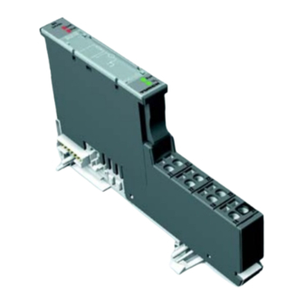
BL20 Components BL20 Components 2.2.1 Gateways The gateway connects the fieldbus to the I/O-modules. It is responsible for handling the entire process data and generates diagnostic information for the higher-level master and the software tool I/O-ASSISTANT. Figure 2-1: BL20 gateway The BL20 gateways BL20-PG-EN offer an integrated power supply unit for feeding the gateway and the connected I/O modules. -
Page 17: Electronics Modules
BL20 Philosophy 2.2.3 Electronics Modules Electronics modules contain the functions of the BL20 modules (power distribution modules, digital and analog input/output modules, and technology modules). Electronics modules are plugged onto the base modules and are not directly connected to the wiring. The assignment table in the Section “Ordering Information“... -
Page 18: Base Modules
BL20 Components 2.2.4 Base Modules The field wiring is connected to the base modules. These are constructed as terminals in block and slice designs and are available in the following variations with either tension clamp or screw connections: 2- /3-wire (2-channel), 4-wire (2-channel) and 4x 2-/3-wire (4-channel). The assignment table in the Section “Ordering Information“... -
Page 19: Bl20 Economy
BL20 Philosophy 2.2.5 BL20 Economy With the BL20 Economy modules the electronics and connection technology is integrated into a single housing. Thus, the selection of a base module is unnecessary. Within a station the Economy modules can be combined with the modules with separate electronics/connection technology, provided that the base modules feature tension spring connections. -
Page 20: End Bracket
BL20 Components 2.2.7 End Bracket A second end bracket to the left of the gateway is necessary, as well as the one mounted into the end plate to secure the station. Figure 2-10: End bracket 2.2.8 Jumpers Jumpers (QVRs) are used to bridge a connection level of a 4-wire base module. They can be used to connect potentials in relay modules (bridging the relay roots);... -
Page 21: Marking Material
BL20 Philosophy 2.2.9 Marking Material Labels: for labeling BL20 electronics modules. Markers: for colored identification of connection levels of BL20 base modules. Dekafix connector markers: for numbering the mounting slots on BL20 base modules. Figure 2-12: Marking materi- 2.2.10 Shield Connection, 2-Pole for Analog Modules The 2-pole shield connection can be used to connect signal-cable shielding to the base modules of analog input and output modules. -
Page 22: Ethernet
Ethernet System Description .......................... 2 3.1.1 Ethernet MAC-ID....................................2 3.1.2 IP address ........................................2 3.1.3 Network Classes....................................3 3.1.4 Data transfer......................................3 – IP (Internet Protocol)..................................3 – TCP (Transmission Control Protocol) ............................3 – Modbus TCP .......................................4 3.1.5 Checking the communication via "ping-signals" ........................4 3.1.6 ARP (Address Resolution Protocol)..............................5 3.1.7 Transmission Media.....................................5... -
Page 23: System Description
ID is determined for each device by the IEEE (Institute of Electrical and Electronics Engineers, New York). The first 3 bytes of the MAC-ID contain a manufacturer identifier (Turck: 00:07:46:××:××:××). The last 3 bytes can be chosen freely by the manufacturer for each device and contain a definite serial number. -
Page 24: Network Classes
System Description 3.1.3 Network Classes The available networks are divided into the different network classes A, B, and C. Table 3-2: Class Network addresses Bytes for net Bytes for host No. of the Network classes address address possible networks/ hosts 1.×××.×××.×××... -
Page 25: Checking The Communication Via "Ping-Signals
Ethernet Modbus TCP In Ethernet TCP/IP networks, Modbus TCP uses the Transport Control Protocol (TCP) for the transmission of the Modbus application protocol. All parameters and data are embedded in the user data of the TCP-telegram using the encapsulation protocol: the client generates a special header (MBAP = Modbus Application Header), which enables the server to clearly interpret the received Modbus-parameters and -commands. -
Page 26: Arp (Address Resolution Protocol)
System Description 3.1.6 ARP (Address Resolution Protocol) In each TCP/IP-capable computer, ARP serves to clearly assign the worldwide unique hardware addresses (MAC-IDs) to the single IP addresses of the network nodes via internal tables. Using ARP in the DOS-prompt, every node in a network can be clearly identified via its MAC-ID. Write a ping command for the respective station/ IP address: (example: "x:\\ping 192.168.1.100"). - Page 27 Ethernet D301049 1211 BL20-PG-EN...
-
Page 28: Technical Features
Technical Features General.............................. 2 Function ............................3 Function ............................4 4.3.1 Programming......................................4 Technical Data........................... 5 4.4.1 Gateway structure....................................5 Connection possibilities........................8 4.5.1 Field bus connection...................................8 – Ethernet-connection..................................8 4.5.2 Power Supply via terminal block with screw connection......................8 4.5.3 Service Interface Connection (female PS/2 connector)......................8 –... -
Page 29: General
Technical Features General This chapter contains the general technical description of the BL20 gateway for Ethernet. The following technical features are independent of the implemented protocol. The chapter describes: the technical data, the connection possibilities, the addressing of the gateway etc. -
Page 30: Function
Function Function This chapter contains the general technical description of the programmable BL20 gateway for Modbus TCP. D301049 1211 BL20-PG-EN... -
Page 31: Programming
Technical Features Function The programmable BL20 gateways can be used as an autonomous PLC or as a de-central PLC in a network interconnection for fast signal processing Hinweis The programmable BL20 gateway BL20-PG-EN is designed as a Single Task System. The gateway handles the entire process data traffic between the I/O-level and the PLC runtime system. -
Page 32: Technical Data
Technical Data Technical Data Figure 4-18: BL20-PG-EN Aservice- interface Bmodule bus LEDs CRUN/STOP-LEDs DSET-button Erotary coding switches FEthernet GEthernet LEDs Hpower supply 4.4.1 Gateway structure The BL20 gateway has the following structure: Figure 4-19: Gateway struc- Fieldbus Service Controller External RAM Module bus (External) interface... -
Page 33: Field Bus Connection
Technical Features Table 4-3: Supply voltage Technical data field supply Ethernet gateway nominal value 24 VDC (18 to 30 VDC) (permissible range) max. field current 10 A System 24 VDC nominal value 24 VDC (18 to 30 VDC) (permissible range) max. - Page 34 Technical Data Processor RISC, 32 bit – Cycle time < 1 ms for 1000 IL-commands (without I/O-cycle) Memory – Program memory 512 KByte – Data memory 512 KByte – Input data 4 KByte (physical input data and network variables) – Output data 4 KByte (physical output data and network variables) –...
-
Page 35: Power Supply Via Terminal Block With Screw Connection
The service interface is designed as a 6 pole Mini-DIN-connection. Two types of cables can be used to connect the service interface () to a PC. special I/O-ASSISTANT-connection cable from TURCK (IOASSISTANT-ADAPTERKABEL-BL20/BL67; Ident-no.: 6827133) Commercially available PS/2 cable with adapter cable... -
Page 36: Connection With I/O-Assistant-Connection Cable
Connection possibilities Connection with I/O-ASSISTANT-Connection Cable Figure 4-21: BL20-gateway connected to PC via special ca- ble^ The I/O-ASSISTANT-cables have a PS/2 male connector (connection for female connector on gateway) and a SUB-D female connector (connection for male connector on PC). Figure 4-22: PS/2 male con- nector on the... -
Page 37: Address Setting
Technical Features Address Setting The addressing of the BL20 Modbus TCP gateway can be realized via different modes: rotary mode (manual addressing via rotary coding-switches) PGM mode (manual addressing via software) BootP mode, DHCP mode (automatic addressing via BootP/DHCP-server at the boot-up of the gateway). -
Page 38: Default Setting Of The Gateway
Address Setting 4.6.2 Default setting of the gateway The gateway’s default-settings are the following: IP address 192.168.1.254 subnet mask 255.255.255.000 default gateway 192.168.1.001 Note The gateway can be reset to these default settings by the user at any time. To reset the gateway, please set the three coding-switches at the gateway to "000" followed by a power-on reset. -
Page 39: Address Setting Via Bootp-Mode
Technical Features The following example shows the setting of the address 173. Figure 4-25: Adr. × 100 Address setting Adr. × 1 Adr. × 10 : 192.168.1.254 1-254 : Static rotary : BootP : DHCP : PGM : PGM-DHCP Attention The settings carried out in the rotary-mode are not stored in the module’s EEPROM. -
Page 40: Address Setting Via Dhcp-Mode
Address Setting Note The IP address as well as the default subnet mask assigned to the gateway by the BootP-server are stored in the gateway’s non-volatile memory. If the gateway is subsequently switched to rotary- or PGM-mode, the settings carried out via BootP (IP address, subnet mask, etc.) will be taken from the module’s EEPROM. -
Page 41: Address Setting Via Pgm-Mode
Technical Features 4.6.6 Address setting via PGM-mode The PGM-mode enables the access of I/O-ASSISTANTs to the module’s network settings. In order to activate the PGM-mode, the rotary coding-switches have to be set to "500". Figure 4-28: Adr. × 100 PGM-mode Adr. -
Page 42: Address-Setting Via I/O-Assistant 3 (Fdt/Dtm)
Naturally, the access to the single station via the service interface at the gateway is possible as well. The IP address, as well as the subnet mask of the TURCK Ethernet modules, can be changed according to the application by using the Busaddress Management function of the BL Service Ethernet interface in the I/O-ASSISTANT. - Page 43 Technical Features Figure 4-30: Busaddress management Figure 4-31: Search for Network- nodes ASearch function in the busaddress management 4-16 D301049 1211 BL20-PG-EN...
- Page 44 Address Setting The IP address as well as the subnet mask of the TURCK Ethernet gateways can be changed according to the application by using the integrated Busaddress Management function in the IO-ASSISTANT 3 (FDT/DTM). Note The access of the IO-ASSISTANT to the gateway is only possible if the gateway is operated in...
-
Page 45: Set Button
Technical Features SET Button The Current Configuration of the station is saved as the Actual Configuration when the SET button on the gateway is pressed for approximately 10 seconds; it is also saved to the both the Temp-Required Configuration Memory and the Required Configuration Memory. The LED "GW" flashes. 4-18 D301049 1211 BL20-PG-EN... -
Page 46: Status Indicators/Diagnostic Messages Gateway
Status Indicators/Diagnostic Messages Gateway Status Indicators/Diagnostic Messages Gateway The gateway sends the following diagnostic messages: undervoltage monitoring for system- and field supply, monitoring of the station status, monitoring of the communication via the internal module bus, monitoring of the communication to Ethernet monitoring of the gateway status Diagnostic messages are displayed in two different ways: via the LEDs... - Page 47 Technical Features Table 4-5: Status Meaning Remedy LED-displays CPU not supplied. Green Firmware active, gateway ready to operate and transmit If LED "IOs" red → Firmware Green, Firmware not active. flashing, download necessary 1 Hz Green, Firmware active, gateway hardware Replace the gateway.
- Page 48 Status Indicators/Diagnostic Messages Gateway Table 4-5: Status Meaning Remedy LED-displays Red/green Adaptable modification of the – Check the physical station for flashing, physically connected station; pulled or new but not planned 1 Hz data transfer possible modules. RUN/STP No program loaded into the –...
- Page 49 Technical Features 4-22 D301049 1211 BL20-PG-EN...
-
Page 50: Implementation Of Modbus Tcp
Implementation of Modbus TCP Modbus Registers ..........................2 Structure of the Packed In-/ Output Process Data ................5 5.2.1 Packed input-process data ................................5 5.2.2 Packed output process data................................6 Data Width of the I/O-Modules in the Modbus-Register Area............7 Register 100Ch: "Gateway-Status" ....................9 Register 1130h: "Modbus-connection-mode"................. -
Page 51: Modbus Registers
Implementation of Modbus TCP Modbus Registers As soon as an application is downloaded to the BL20-PG-EN, the programmable gateway simply allows read-only-access to the standard Modbus registers (0×0000h to 0×01FFh, 0×0800h to 0×09FFh). A write-access is only possible using the Modbus output registers (register 0×4400 to 0×47FF, see following table). - Page 52 Modbus Registers Table 5-6: Address (hex.) Access Description Modbus registers of the gateway ro = read only rw = read write 0×1120 watchdog predefined time [ms] (default: 0) 0×1121 watchdog reset register 0×1130 modbus connection mode register, page 5-10 0×1131 modbus connection time-out in seconds (default: 0 = never) 0×113C to modbus parameter restore,...
- Page 53 Implementation of Modbus TCP Table 5-6: Address (hex.) Access Description Modbus registers of the gateway ro = read only rw = read write 0×A000 to diagnostics (max. 74 modules per station × 32 registers per 0×A93F module) 0×B000 to parameters (max. 74 modules per station × 32 registers per 0×B93F module) D301049 1211 BL20-PG-EN...
-
Page 54: Structure Of The Packed In-/ Output Process Data
Structure of the Packed In-/ Output Process Data Structure of the Packed In-/ Output Process Data In order to assure a largely efficient access to the process data of a station, the module data are consistently packed and mapped to a coherent register area. The I/O-modules are divided into digital and intelligent modules (analog modules, serial interfaces). -
Page 55: Packed Output Process Data
Implementation of Modbus TCP 5.2.2 Packed output process data output register area: 0800h to 09FFh 0800h 09FFh intelligent modules, output data digital output data free Note Independent of the I/O-configuration, an access to all 512 registers is always possible. Registers that are not used send a "0" answering read access, write accesses are ignored. D301049 1211 BL20-PG-EN... -
Page 56: Data Width Of The I/O-Modules In The Modbus-Register Area
Data Width of the I/O-Modules in the Modbus-Register Area Data Width of the I/O-Modules in the Modbus-Register Area The following table shows the data width of the BL20 I/O-modules within the modbus register area and the type of data alignment. Table 5-7: Module Process... - Page 57 Implementation of Modbus TCP Table 5-7: Module Process Process output Alignment Data width of input the I/O-modules A The process data – technology modules of the SWIRE- BL20-1RS××× 4 words 4 words word by word modules are mapped into the BL20-1SSI 4 words 4 words...
-
Page 58: Register 100Ch: "Gateway-Status
Register 100Ch: "Gateway-Status" Register 100Ch: "Gateway-Status" This register contains a general gateway-/ station-status. Table 5-8: Name Description Register 100Ch: Gateway gateway-status I/O Controller Error The communication controller for the I/O-system is faulty. Force Mode Active Error The Force-Mode it activated. The state of the outputs may no longer accord to the settings made via the fieldbus. -
Page 59: Register 1130H: "Modbus-Connection-Mode
Implementation of Modbus TCP Register 1130h: "Modbus-connection-mode" This register defines the behavior of the Modbus connections: Table 5-9: Name Description register 1130h: 15 to 2 reserved Modbus- Connection- MB_ImmediateWritePermission Mode – 0: With the first write access, a write authorization for the respective Modbus- connection is requested. -
Page 60: Register 0×113E And 0×113F: "Save Modbus-Connection Parameters
Register 0×113E and 0×113F: "Save Modbus-connection parameters" Register 0×113E and 0×113F: "Save Modbus-connection parameters" Registers 0×113E and 0×113F are used for the non-volatile saving of parameters in registers 0×1120 and 0×1130 to 0×113B. For this purpose, write "0×7361" in register 0×113E. To activate the saving of the registers, write "0×7665"... -
Page 61: The Service-Object
Implementation of Modbus TCP The Service-Object The service-object is used to execute one-time or acyclic services. It is an acknowledge service which may serve, for example, to parameterize an I/O-module. 2000h 2080h 20FFh service request area service response area The service request area allows write access, the service response area only read access. Service request area 2000h 2001h... -
Page 62: Indirect Reading Of Registers
The Service-Object Supported service numbers:: Table 5-10: Service code Meaning Supported 0×0000 no function service numbers: 0×0003 indirect reading of registers 0×0010 indirect writing of registers A service request may have the following results: Table 5-11: Service code Meaning results of the 0×0000 error free execution of service service request... -
Page 63: Indirect Writing Of Registers
Implementation of Modbus TCP 5.9.2 "Indirect writing of registers" 1 to 122 (Count) Modbus-registers are written, starting with address x (Addr). service-request 2000h 2001h 2002h 2003h 2004h 2005h 207Fh service no. 0x0000 0x0010 Addr Count register contents service-response 2080h 2081h 2082h 2083h 2084h... -
Page 64: Mapping: Input-Discrete- And Coil-Areas
Mapping: Input-Discrete- and Coil-Areas 5.10 Mapping: Input-Discrete- and Coil-Areas Function codes FC1 ("Read Coils"), FC2 ("Read Discrete Inputs"), FC 5 ("Write Single Coil") and FC15 ("Write Multiple Coils") allow single-bit access to in- and output data. The data mapping in these areas is the following: Mapping: input-discrete-area All digital inputs are stored in this area (offset "0"). -
Page 65: Mapping The Modbus Registers
Implementation of Modbus TCP 5.11 Mapping the Modbus Registers Figure 5-33: PC or PLC BL20-PG-EN Mapping the Modbus regis- PC or PLC BL20-PG-EN ters MODBUS registers BL20-registers Inputs: MODBUS registers BL20-registers Read only access Inputs: Read only access 4000 Output register 0 4000 Output register 0 4001... -
Page 66: Implemented Modbus Functions
Implemented Modbus Functions 5.12 Implemented Modbus Functions The BL20 gateway for Ethernet supports the following functions for accessing process data, parameters, diagnostics and other services. Table 5-12: Function Codes Implemented Function functions Description Read Coils Serves for reading multiple output bits. Read Discrete InputS Serves for reading multiple input bits Read Holding Registers... -
Page 67: Parameters Of The Modules
Implementation of Modbus TCP 5.13 Parameters of the Modules 5.13.1 Digital input modules BL20-4DI-NAMUR Table 5-13: Byte Parameter name Vale Module - Meaning parameters 0 to 3 input filter× 0 = deactivate A Default – (input filter 0,25 ms) settings 1 = activate –... - Page 68 Parameters of the Modules BL20-2AI-I(0/4...20MA) (1 byte parameter per channel) Table 5-15: Byte Parameter name Value Module – Meaning parameters current mode 0 = 0...20 mA 1 = 4...20 mA A Default- settings value representation 0 = Integer (15 bit + sign) 1 = 12 bit (left justified) diagnosis 0 = activate...
- Page 69 Implementation of Modbus TCP BL20-2AI-PT/NI-2/3 (2 byte parameter per channel) Table 5-18: Byte Parameter name Value Module – Meaning parameters mains 0 = 50 Hz suppression 0 = 60 Hz A Default- settings value 0 = Integer (15 bit + sign) representation 1 = 12 bit (left justified) diagnosis...
- Page 70 Parameters of the Modules BL20-2AI-THERMO-PI (2 byte parameter per channel) Table 5-19: Byte Parameter name Value Module – Meaning parameters mains suppression 0 = 50 Hz 0 = 60 Hz A Default- settings value representation 0 = Integer (15 bit + sign) 1 = 12 bit (left justified) diagnosis 0 = release...
- Page 71 Implementation of Modbus TCP BL20-2AIH-I Table 5-20: Byte Parameter name Value Module parameters A Default- settings Channel 0 = activate (channel 1) 1 = deactivate Short-circuit diagnostics 0 = block 1 = release Wire Break diagnostics 0 = block 1 = release 3 + 4 Operation mode 0 = 0…...
- Page 72 Parameters of the Modules Table 5-20: Byte Parameter name Value Module parameters A Default- settings HART-variable B Defines the channel from which the HART-vari- able is read. Mapped channel Vx 0 = channel 1 1 = channel 2 6 + 7 Mapped variable Vx Defines which HART-variable of the connected sensor is mapped into the module’s process data.
- Page 73 Implementation of Modbus TCP BL20-4AI-U/I (1 byte parameter per channel) Table 5-21: Byte Parameter name Value Module – Meaning parameters 0 to 3 range 0 = 0...10 V/ 0...20 mA 1 = -10...+10 V/ 4...20 mA A Default- settings value representation 0 = Integer (15 bit + sign) 1 = 12 bit (left justified) diagnosis...
- Page 74 Parameters of the Modules BL20-E-8AI-U/I-4PT/NI (1 byte per channel) Table 5-22: Byte Parameter Value Meaning Module name parameters A Default- 0 to 7 0 to 5 Operation 000000 voltage, -10...10 VDC, standard settings mode Kx 000001 voltage, 0...10 VDC, standard B 3-wire- measurment: 000010...
- Page 75 Implementation of Modbus TCP Table 5-22: Byte Parameter Value Meaning Module name parameters Operation 011110 Pt 1000, -200°C...850 °C, 3-wire mode Kx 011111 Pt 1000, -200°C...150 °C, 3-wire 100000 Ni 100, -60 °C...250 °C, 2-wire 100001 Ni 100, -60°C...150 °C, 2-wire 100010 Ni 1000, -60 °C...250 °C, 2-wire 100011...
-
Page 76: 5.13.3 Analog Output Modules
Parameters of the Modules 5.13.3 Analog output modules BL20-1AO-I(0/4...20MA) (3 byte per channel) Table 5-23: Byte Parameter name Value Module – Meaning parameters current mode 0 = 0...20 mA 1 = 4...20 mA A Default- settings value representation 0 = Integer (15 bit + sign) 1 = 12 bit (left justified) 2 to 7 reserved... - Page 77 Implementation of Modbus TCP BL20-2AO-U(-10/0...+10VDC) (3 byte per channel) Table 5-25: Byte Parameter name Value Module – Meaning parameters voltage mode 0 = 0...10 V 1 = -10...+10 V A Default- settings value 0 = Integer (15 bit + sign) representation 1 = 12 bit (left justified) reserved...
- Page 78 Parameters of the Modules Table 5-26: Byte Parameter name Value Module para- meters A Default settings Value representation 0 = Integer (15 bit + sign) (channel 1) 1 = NE 43 2 = Extended Range 6 + 7 Behavior module bus error In Modbus TCP, the output of a substitute value in case of an error is not possible 2 + 3...
- Page 79 Implementation of Modbus TCP Table 5-26: Byte Parameter name Value Module para- meters A Default settings HART-variable C Defines the channel from which the HART- variable is read. Mapped channel Vx 0 = channel 1 1 = channel 2 6 + 7 Mapped variable Vx Defines which HART-variable of the connected sensor is mapped into the...
- Page 80 Parameters of the Modules BL20-E-4AO-U/I (3 byte per channel) Table 5-27: Byte Parameter Value Meaning Module name parameters A Default- 0/3/6/9 0 to 3 Operation 0000 voltage, -10...10 V DC, standard settings mode Kx 0001 voltage, 0...10 V DC, standard 0010 voltage, -10...10 V DC, PA NE 43 0011...
-
Page 81: 5.13.4 Technology Modules
Implementation of Modbus TCP 5.13.4 Technology modules BL20-1CNT, Counter mode Table 5-28: Byte Parameter name Value Module – Meaning parameters A Default settings 0 to 5 Counter mode 100000 = continous count 100001 = single-action count 100010 = periodical count gate function 0 = abort count procedure 1 = interrupt count procedure... - Page 82 Parameters of the Modules Table 5-28: Byte Parameter name Value Module – Meaning parameters A Default settings Substitute value DO Diagnostic DO1 0 = on 1 = off 2/ 3 Function DO1 00 = output 01 = on when cnt value >= ref. value 10 = on when cnt value <= ref.
- Page 83 Implementation of Modbus TCP BL20-1CNT-24VDC, measurement mode Table 5-29: Byte Parameter name Value Module – Meaning parameters A Default settings 0 to 5 Measurement mode 100000 = frequency measurement 100001 = revolutions measurement 100010 = period duration measure- ment Digital input DI 0 = normal 1 = inverted Function DI...
- Page 84 Parameters of the Modules Table 5-29: Byte Parameter name Value Module – Meaning parameters A Default settings Sensor (A) 0 = normal 1 = inverted Direction input (B) 0 = normal 1 = inverted Group 0 = release diagnostics 1 = block 4/ 5 Behaviour CPU/master STOP 00 = turn off DO1...
- Page 85 Implementation of Modbus TCP BL20-1RS232 Table 5-30: Byte Parameter name Value Module – Meaning parameters A Default- settings 3 to 0 data rate 0000 = 300 bps 0001 = 600 bps 0010 = 1200 bps 0100 = 2400 bps 0101 = 4800 bps 0110 = 9600 bps...
- Page 86 Parameters of the Modules Table 5-30: Byte Parameter name Value Module – Meaning parameters A Default- settings data flow control 00 = none – the data flow control is deactivated 01 = XON/XOFF – Software-Handshake (XON/XOFF) is activated 10 = RTS/CTS –...
- Page 87 Implementation of Modbus TCP BL20-1RS485/422 Table 5-31: Byte Parameter name Value Module – Meaning parameters A Default- settings 3 to 0 data rate 0000 = 300 bps 0001 = 600 bps 0010 = 1200 bps 0100 = 2400 bps 0101 = 4800 bps 0110 = 9600 bps...
- Page 88 Parameters of the Modules Table 5-31: Byte Parameter name Value Module – Meaning parameters A Default- settings data bits 0 = 7 – The number of data bits is 7. 1 = 8 – The number of data bits is 8. BL20-1SSI Table 5-32: Byte...
- Page 89 Implementation of Modbus TCP Table 5-32: Byte Parameter name Value Module – Meaning parameters A Default- settings 6 to 4 Number of invalid bits (MSB) Number of invalid bits on the MSB side of the position value supplied by the SSI encoder.
- Page 90 Parameters of the Modules BL20-E-1SWIRE Bit 7 Bit 6 Bit 5 Bit 4 Bit 3 Bit 2 Bit 1 Bit 0 Byte 1 Configura- Disable reserved free free free tion Byte 2 free AUXERR INFO INFO INFO Byte 3 reserved Byte 4 reserved (lifeguarding time up to version VN 01-03) Byte 5...
- Page 91 Implementation of Modbus TCP Table 5-33: Parameter Value Module name parameters Byte 1 Configuration check active/ Bus or slave-oriented configuration check (without function if MC = 1) passive 0 = bus based If the PLC configuration check is activated, data exchange is only started if the configuration stored in the BL20-E-1SWIRE fully matches the SET configuration stored in the PLC.
- Page 92 Parameters of the Modules Table 5-33: Parameter Value Module name parameters Byte 2 Group PKZ error field Activate slave diagnostics PKZ Sx. As soon as only one SWIRE-DIL slave on the bus clears its PKZ bit, this is indicated as an error depending on the parameter setting. 0 = active Group diagnostics is activated 1 = inactive...
- Page 93 Byte 9 bis 24 Device ID, TYPE setting for the LIN slave at position x on the SWIRE bus slave x 0x20 SWIRE-DIL-MTB (: 0xFF) 0xFF Basic setting (no slave) BL20-E-2CNT-2PWM (see separate module-manual D301224) BL20-2RFID-S (see RFID-documentation www.turck.de) 5-44 D301049 1211 BL20-PG-EN...
-
Page 94: Diagnostic Messages Of The Modules
Diagnostic Messages of the Modules 5.14 Diagnostic Messages of the Modules 5.14.1 Power Supply Modules BL20-BR-24VDC-D Table 5-34: Diagnostic Diagnostics BL20-BR-24VDC- byte Module bus undervoltage warning reserved Undervoltage field supply reserved BL20-PF-24VDC-D Table 5-35: Diagnostic Diagnostics BL20-PF-24VDC- byte reserved reserved undervoltage field supply reserved BL20-PF-120/230VAC-D... -
Page 95: Digital Input Modules
Implementation of Modbus TCP 5.14.2 Digital Input Modules BL20-4DI-NAMUR Table 5-37: Diagnostic Diagnostics BL20-4DI-NAMUR byte short circuit sensor 1 open circuit sensor 1 short circuit sensor 2 open circuit sensor 2 short circuit sensor 3 open circuit sensor 3 short circuit sensor 4 open circuit sensor 4 5.14.3 Analog Input Modules... - Page 96 Diagnostic Messages of the Modules BL20-2AI-U(-10/0...+10VDC) Table 5-41: Diagnostic Diagnostics BL20-2AI-U byte (-10/0...+10VDC measurement value range error (channel 1) measurement value range error (channel 2) BL20-2AI-PT/NI-2/3 Table 5-42: Diagnostic Diagnostics BL20-2AI-PT/NI- byte A threshold: Measurement value range error 1% of the (channel 1) (Underflow diagnostics in temperature measurement ranges only) positive...
- Page 97 Implementation of Modbus TCP BL20-2AIH-I Table 5-44: Diagnosis byte Diagnosis BL20-2AIH-I Overflow The measured value exceeds the upper measurement range and the module can not process the value. Wire break Shows a wire break in the signal line. Short-circuit Shows a short-circuit in the signal line Underflow The measured value is lower than the lower measurement range and the module can not process the value.
-
Page 98: Digital Output Modules
Diagnostic Messages of the Modules BL20-8AI-U/I-4PT/NI Table 5-46: Diagnosis byte Diagnosis BL20-8AI-U/I- 4AI-PT/NI A thresholds: measurement value range error (OoR) value (channel 0) wire break (WB) representation to n + 7 of the module in (channel 7) short-circuit (SC) manual D300716 overflow / underflow (OUFL) 4 to 6... - Page 99 Implementation of Modbus TCP BL20-16DO-24VDC-0.5A-P Table 5-51: Diagnostic Diagnostics BL20-16DO- byte 24VDC-0.5A-P Overcurrent (short-circuit channel 1-4) Overcurrent (short-circuit channel 5-8) Overcurrent (short-circuit chnnel 9-12) Overcurrent (short-circuit channel 13-16) BL20-32DO-24VDC-0.5A-P Table 5-52: Diagnostic Diagnostics BL20-32DO- byte 24VDC-0.5A-P Overcurrent (short-circuit channel 1-4) Overcurrent (short-circuit channel 5-8) Overcurrent (short-circuit chnnel 9-12) Overcurrent (short-circuit channel 13-16)
-
Page 100: 5.14.5 Analog Output Modules
Diagnostic Messages of the Modules 5.14.5 Analog output modules BL20-2AOH-I Table 5-53: Diagnosis byte Diagnosis BL20-2AOH-I Value above upper limit Display of a measurement range exceeding → limit values according to parameterization Wire break Shows a wire break in the signal line. Invalid value The output value exceeds the values which the module is able to inter- pret. -
Page 101: Technology Modules
Implementation of Modbus TCP 5.14.6 Technology Modules BL20-1CNT-24VDC Table 5-55: Diagnostic Diagnostics BL20-1CNT- byte 24VDC Short-circuit / open circuit → ERR_DO If bit 7 = 0 Short-circuit in sensor power supply → ERR-24VDC (counter mode) End of counter range wrong Start of counter range wrong Invert-DI+latch-retr. - Page 102 Diagnostic Messages of the Modules BL20-1RS485/422 Table 5-57: Diagnostic Diagnostics BL20-1RS485/422 byte parameterization error hardware failure data flow control error (only in RS422-mode) frame error buffer overflow BL20-1SSI Table 5-58: Diagnostic Diagnostics BL20-1SSI byte SSI group diagnostics open circuit sensor value overflow sensor value underflow parameterization error 5-53...
- Page 103 Implementation of Modbus TCP BL20-E-1SWIRE Bit 7 Bit 6 Bit 5 Bit 4 Bit 3 Bit 2 Bit 1 Bit 0 Byte n GENEAL free free free SWERR Byte n+1 free free free free AUXERR Field Byte n+2 Byte n+3 S16 TYP S15 TYP S14 TYP...
- Page 104 Diagnostic Messages of the Modules Table 5-59: Designation Value Meaning Meaning of diagnostics data bits Communication SWIRE A communication error is present, such as a slave is no longer reached, its internal timeout has elapsed or communication is faulty. The master cannot carry out data exchange with at least one slave.
- Page 105 Implementation of Modbus TCP Table 5-59: Designation Value Meaning Meaning of diagnostics data bits TYPE Configuration If the TYP parameter is set with group diagnostics in the parameter setting, this bit indicates an error as soon as a PLC configuration check detects differing slave numbers, types or position of an SWIRE slave.
- Page 106 The PKZ of the slave has tripped. Hinweis The error messages U ERR, TYPE , TYPE Sx, PKZ , PKZ Sx, SD and SD Sx can be deactivated via the parameter setting. BL20-E-2CNT-2PWM (see separate module-manual D301224) BL20-2RFID-S (see RFID-documentation www.turck.de) 5-57 D301049 1211 BL20-PG-EN...
- Page 107 Implementation of Modbus TCP 5-58 D301049 1211 BL20-PG-EN...
- Page 108 Configuration of the BL20-PG-EN with CoDeSys General.............................. 2 6.1.1 System requirements..................................2 Installation of the BL20 target files ....................3 6.2.1 Installation ......................................3 BL20 Hardware Configuration ......................6 Configuration/ Programming of the PG in CoDeSys ................. 7 6.4.1 Creating a new project..................................7 –...
-
Page 109: Configuration Of The Bl20-Pg-En With Codesys
Modbus TCP in CoDeSys (Controller Development System) from "3S - Smart Software Solutions GmbH" on the basis of an example. 6.1.1 System requirements Installation of CoDeSys (version 2.3.5.8) Installation of the BL20 target files "TSP_Turck_×××.zip" (can be downloaded from www.turck.com) Figure 6-34: CoDeSys from D301049 1211 BL20-PG-EN... -
Page 110: Installation Of The Bl20 Target Files
Support Package (short: targets) have to be installed. Target files contain all information necessary for integrating a system into the programming tool. The Target Support Package (TSP) for the BL20-PG-EN can be downloaded from the TURCK homepage as a zipped archive (TSP_Turck_BL20_PG_EN ×××.zip). - Page 111 Configuration of the BL20-PG-EN with CoDeSys Search the target information file "BL20-×××.tnf" using the "Open" button and add the TURCK gateways to "Possible Targets". Figure 6-37: Select the target file The BL20 target is installed using the "Install" button. D301049 1211 BL20-PG-EN...
- Page 112 Installation of the BL20 target files The BL20-PG-EN can now be found under "Installed Targets" and can be chosen in CoDeSys as a target now. Figure 6-38: Installation of the TURCK tar- D301049 1211 BL20-PG-EN...
-
Page 113: Bl20 Hardware Configuration
Configuration of the BL20-PG-EN with CoDeSys BL20 Hardware Configuration 1 At first, configure your BL20 station (BL20-PG-EN and I/O modules) and switch on the power supply. 2 The gateway saves the actual station configuration, if the SET button under the cover on the gateway is pressed for approx. -
Page 114: Configuration/ Programming Of The Pg In Codesys
Configuration/ Programming of the PG in CoDeSys Configuration/ Programming of the PG in CoDeSys 6.4.1 Creating a new project Start the Software an create a new project using the "File → New"-command. Chose the BL20-PG-EN as target. Normally, a further configuration of the gateway in the dialog box „target settings“ is not necessary. Note The BL20-PG-EN uses the word addressing mode (see the following table). -
Page 115: Communication Parameters Of The Target
Configuration of the BL20-PG-EN with CoDeSys Figure 6-40: New CoDeSys- project Now, the communication parameters for the target have to be adapted. Communication parameters of the target Figure 6-41: Opening the communica- tion parameters Mark "’localhost’ via TCP/IP" in the „Channels“ field and define a new channel by pressing the „New“ button. - Page 116 Configuration/ Programming of the PG in CoDeSys 2 Ethernet connector (M12, 4-pole, D-coded) for a „TCP/IP (Level 2)"-communication. Figure 6-42: Defining a new channel D301049 1211 BL20-PG-EN...
- Page 117 Configuration of the BL20-PG-EN with CoDeSys Select the preferred interface and set the parameters depending on the interface as follows: 1 serial RS232-communication: Figure 6-43: Setting the communica- tion parameters for RS232 Attention The Parameter "Motorola byteorder" must be set to "YES". Otherwise, no error-free communication with the gateway is possible.
- Page 118 Configuration/ Programming of the PG in CoDeSys 2 TCP/IP (Level 2)-communication Adapt the gateway’s communication parameters (IP address, Motorola byteorder) as shown in the following figure. Figure 6-44: Setting the communica- tion parameters for TCP/IP (Level Attention The Parameter "Motorola byteorder" must be set to "YES". Otherwise, no error-free communication with the gateway is possible.
-
Page 119: Configuration Of The Bl20 Station
Configuration of the BL20-PG-EN with CoDeSys Configuration of the BL20 Station Open the „PLC Configuration“ in the „Resources“ tab. Figure 6-45: PLC Configura- tion Mark the BL20-IO[SLOT] and add the I/O modules to the gateway in the „Input/Output“ tab. Figure 6-46: Selecting the I/O modules Attention... -
Page 120: Parameterization Of The I/O Modules
Configuration of the BL20 Station 6.5.1 Parameterization of the I/O modules For the parameterization of an I/O module mark the respective module in the „Selected Modules“ field and press the „Properties“ button. In the „Module Properties“ dialog box each Parameter can be changed by double clicking the „Value“. Figure 6-47: Parameteriza- tion of I/O mod-... -
Page 121: Mapping Of The Modbus Registers
Configuration of the BL20-PG-EN with CoDeSys A double click directly to the left of the entry of automatic addressing „AT%...“ opens the input field for the symbolic addressing. Figure 6-49: Symbolic addressing 6.5.3 Mapping of the Modbus Registers In order to enable Modbus communication of BL20-PG-EN with other Modbus nodes, the Modbus registers have to be added to the PLC configuration. - Page 122 Configuration of the BL20 Station The in- and output addresses are automatically assigned to the Modbus registers. Figure 6-51: Configuration of modbus reg- isters Therefore, a symbolic address allocation is also recommended for the in- and output words of the Modbus registers (see also Note on page 6-13).
-
Page 123: Plc-Programming
Configuration of the BL20-PG-EN with CoDeSys PLC-Programming Programming is done in the "POUs" tab. Figure 6-53: Programming in "POUs" tab After the completion of the program, it is compiled using the „Project → Rebuild all..." command. 6.6.1 Online The connection to the gateway is established with "Online → Login". Figure 6-54: Download of the program... -
Page 124: Creating A Boot Project
PLC-Programming Download the program to the gateway and start it with "Online → Run". Figure 6-55: Starting the program Note Please observe, projects must be downloaded and saved as boot projects (for further information see the description in the following section Creating a boot project) in order to be stored permanently to the gateway! - Page 125 Configuration of the BL20-PG-EN with CoDeSys 6-18 D301049 1211 BL20-PG-EN...
-
Page 126: Guidelines For Station Planning
Guidelines for Station Planning Random Module Arrangement ......................2 7.1.1 Complete Planning....................................2 7.1.2 Maximum System Extension................................2 Power Supply ............................ 4 7.2.1 Module Bus Refreshing ..................................4 7.2.2 Creating Potential Groups ................................7 7.2.3 Protecting the Service Interface on the Gateway........................8 7.2.4 C-Rail (Cross Connection)..................................9 7.2.5 Direct Wiring of Relay Modules.............................. -
Page 127: Random Module Arrangement
Guidelines for Station Planning Random Module Arrangement The arrangement of the I/O-modules within a BL20 station can basically be chosen at will. Nevertheless, it can be useful with some applications to group certain modules together. Attention Please observe, that RFID modules used within a station always have to be mounted directly following the gateway (slot 1 to 34). - Page 128 Random Module Arrangement The following overview shows the maximum number of channels possible, on condition that the entire station is made up of that respective type of channel only: Table 7-60: Channels Modules Maximum Type Max. no. Type Max. no. system extension, process data...
-
Page 129: Power Supply
Guidelines for Station Planning Power Supply 7.2.1 Module Bus Refreshing The number of BL20 modules that can be supplied by the gateway or a separate Bus Refreshing module via the internal module bus depends on the respective nominal current consumption of the individual modules on the module bus. - Page 130 Power Supply The calculation shows that an additional/further Bus Refreshing module is required at the latest following the last BL20-2AO module. This Bus Refreshing module is sufficient to supply the remaining modules. Note The power requirements of the BL20 gateway is to be considered when calculating the required number of Bus Refreshing modules.
- Page 131 Guidelines for Station Planning Table 7-61: Module Supply Nominal current consumption Nominal current consumption of the BL20 modules on the module bus BL20-4DO-24VDC-0.5A-P 30 mA BL20-E-8DO-24VDC-P 15 mA BL20-16DO-24VDC-0.5A-P 120 mA BL20-E-16DO-24VDC-P 25 mA BL20-32DO-24VDC-0.5A-P 30 mA BL20-1AO-I(0/4...20MA) 39 mA BL20-2AO-I(0/4...20MA) 40 mA BL20-2AO-U(-10/0...+10VDC)
-
Page 132: Creating Potential Groups
Power Supply Figure 7-57: Gatew ay 2 DI 2 DO 2 DI 2 DO 2 DI 1 AO 2 DI Power supply of the station 10/100 MBit – Field SBBC-B supply – – Field supply System sypply It must be ensured that the same ground potential and ground connections are used. If different ground potentials or ground connections are used, compensating currents flow via the module bus, which can lead to the destruction of the Bus Refreshing module. -
Page 133: Protecting The Service Interface On The Gateway
Guidelines for Station Planning Figure 7-58: 2 DI 2 DO 2 DI 2 DO 2 DI Example for creating poten- tial groups 10/100 MBit – Field 2L+ 2L- supply Potential group 2 Potential group 1 – System supply Note The system can be supplied with power independent of the potential group formation described above. -
Page 134: C-Rail (Cross Connection)
Power Supply 7.2.4 C-Rail (Cross Connection) The C-rail runs through all base modules. The C-rail of the base modules for power distribution modules is mechanically separated; thus potentially isolating the adjoining supply groups. Access to the C-rail is possible with the help of base modules with a C in their designation (for example, BL20-S4T-SBCS). -
Page 135: Direct Wiring Of Relay Modules
Guidelines for Station Planning Figure 7-61: 2 DO 2 DI 2 DO 2 DI 2 DO 2 DI 2 DO 2 DI Using the C-rail as a protective earth terminal 10/100 MBit C-rail (PE) SBBS SBBC SBBC C-rails can be used for a common voltage supply when relay modules are planned. To accomplish this, the load voltage is connected to a Power Feeding module with the BL20-P4x-SBBC base module with tension clamp or screw connection. -
Page 136: Plugging And Pulling Electronics Modules
Plugging and Pulling Electronics Modules Plugging and Pulling Electronics Modules BL20 enables the pulling and plugging of electronics modules without having to disconnect the field wiring. The BL20 station remains in operation if an electronics module is pulled. The voltage and current supplies as well as the protective earth connections are not interrupted. -
Page 137: Extending An Existing Station
Guidelines for Station Planning Extending an Existing Station Attention Please note that extensions to the station (mounting further modules) should be carried out only when the station is in a voltage-free state. 7-12 D301049 1211 BL20-PG-EN... -
Page 138: Firmware Download
Firmware Download Firmware Download Firmware can be downloaded via the service interface on the gateway using the software tool I/O- ASSISTANT. More information is available in the program’s online help. Attention The station should be disconnected from the fieldbus when downloading. Firmware must be downloaded by authorized personnel only. - Page 139 Guidelines for Station Planning 7-14 D301049 1211 BL20-PG-EN...
-
Page 140: Guidelines For Electrical Installation
Guidelines for Electrical Installation General Notes............................ 2 8.1.1 General........................................2 8.1.2 Cable Routing ......................................2 8.1.3 Cable Routing Inside and Outside of Cabinets..........................2 – Cable Routing Outside Buildings ...............................2 8.1.4 Lightning Protection...................................3 8.1.5 Transmission Media.....................................3 Potential Relationships........................4 8.2.1 General........................................4 Electromagnetic Compatibility (EMC)....................5 8.3.1 Ensuring Electromagnetic Compatibility ............................5 8.3.2... -
Page 141: General Notes
Guidelines for Electrical Installation General Notes 8.1.1 General Cables should be grouped together, for example: signal cables, data cables, heavy current cables, power supply cables. Heavy current cables and signal or data cables should always be routed in separate cable ducts or bundles. -
Page 142: Lightning Protection
(10BaseT) with shielding (STP) or without shielding (UTP). Note TURCK offers a variety of cable types for fieldbus lines as premoulded or bulk cables with different connectors. The ordering information for the available cable types can be found in the BL20 catalog. -
Page 143: Potential Relationships
Guidelines for Electrical Installation Potential Relationships 8.2.1 General The potential relationship of a Ethernet system realized with BL20 modules is characterized by the following: The system supply of gateway and I/O-modules as well as the field supply are realized via one power feed at the gateway. -
Page 144: Electromagnetic Compatibility (Emc)
Electromagnetic Compatibility (EMC) Electromagnetic Compatibility (EMC) BL20 products comply in full with the requirements pertaining to EMC regulations. Nevertheless, an EMC plan should be made before installation. Hereby, all potential electromechanical sources of interference should be considered such as galvanic, inductive and capacitive couplings as well as radiation couplings. -
Page 145: Mounting Rails
Guidelines for Electrical Installation 8.3.5 Mounting Rails All mounting rails must be mounted onto the mounting plate with a low impedance, over a large surface area, and must be correctly earthed. Figure 8-64: Mounting options A TS 35 B Mounting rail C Mounting plate Mount the mounting rails over a large surface area and with a low impedance to the support system using screws or rivets. -
Page 146: Shielding Of Cables
Shielding of cables Shielding of cables Shielding is used to prevent interference from voltages and the radiation of interference fields by cables. Therefore, use only shielded cables with shielding braids made from good conducting materials (copper or aluminum) with a minimum degree of coverage of 80 %. The cable shield should always be connected to both sides of the respective reference potential (if no exception is made, for example, such as high-resistant, symmetrical, analog signal cables). -
Page 147: Potential Compensation
Guidelines for Electrical Installation Potential Compensation Potential differences can occur between installation components that are in separate areas and these are fed by different supplies, have double-sided conductor shields which are grounded on different installation components. A potential-compensation cable must be routed to the potential compensation. Danger Never use the shield as a potential compensation. -
Page 148: Bl20-Approvals For Zone 2/ Division
BL20-Approvals for Zone 2/ Division 2 Note The Zone 2 - approval certificates for BL20 can be found in a separate manual for approvals D301255 on www.turck.de. D301049 1211 BL20-PG-EN... - Page 149 BL20-Approvals for Zone 2/ Division 2 D301049 1211 BL20-PG-EN...
-
Page 150: 10 Appendix
10 Appendix 10.1 Network Configuration ........................2 10.1.1 Changing the IP address of a PC/ network interface card.....................2 – Changing the IP address in Windows 2000/ Windows XP ....................2 – Changing the IP address in Windows NT ..........................3 – Changing the IP address via I/O-ASSISTANT..........................4 10.1.2 Deactivating/ adapting the firewall in Windows XP........................5 D301049 1211 BL20-PG-EN... -
Page 151: Network Configuration
Appendix 10.1 Network Configuration Note In order to build up the communication between the BL20-gateway and a PLC/ PC or a network interface card, both devices have to be hosts in the same network. The network is already defined by the default-settings in the BL20-gateways. The default IP address for the BL20-gateways is 192.168.1.1 (see also chapter page... -
Page 152: Changing The Ip Address In Windows Nt
Network Configuration 3 Activate "Use the following IP address" and assign an IP address of the network mentioned above to the PC/ Network interface card (see the following figure). Figure 10-66: Changing the PC’s IP address Changing the IP address in Windows NT 1 Open the folder "Network"... -
Page 153: Changing The Ip Address Via I/O-Assistant
Appendix 3 Activate "Specify IP address " and set the address as follows. Figure 10-68: Specify IP address Changing the IP address via I/O-ASSISTANT The Address Tool integrated in the I/O-ASSISTANT offers the possibility to browse the whole Ethernet network for connected nodes and to change their IP address as well as the subnet mask according to the application (for further information, please read Address-setting via I/O-ASSISTANT 3 (FDT/DTM) (page... -
Page 154: 10.1.2 Deactivating/ Adapting The Firewall In Windows Xp
Network Configuration 10.1.2 Deactivating/ adapting the firewall in Windows XP If Windows XP is used as operating system, problems with the system-integrated firewall may occur in case of an access of outside sources to your computer or in case of tools like the I/O-ASSISTANT which are used for changing the IP address of the gateways. - Page 155 Appendix Adapting the firewall The firewall remains active, the option "Don’t allow exceptions" it deactivated: Figure 10-70: Activating the Windows firewall In the "Exceptions"-tab, add the programs or services for which you want to allow the access to your computer. Figure 10-71: "Exceptions"-tab Note...
-
Page 156: 11 Glossary
11 Glossary Acknowledge Acknowledgment of a signal received. Active metal component Conductor or conducting component that is electrically live during operation. Address Identification number of, e.g. a memory position, a system or a module within a network. Addressing Allocation or setting of an address, e. g. for a module in a network. Used to definitely allocate the hardware addresses (MAC-IDs) assigned worldwide to the IP addresses of the network clients via internal tables. - Page 157 Glossary Bus system All units which communicate with one another via a bus. Capacitive coupling Electrical capacitive couplings occur between cables with different potentials. Typical sources of interference are, for example, parallel-routed signal cables, contactors and electrostatic discharges. Check-back interface The check-back interface is the interface from the counter module to the internal module bus.
- Page 158 German acronym for European Standard. Electrostatic Discharge. Field power supply Voltage supply for devices in the field as well as the signal voltage. Fieldbus Data network on sensor/actuator level. A fieldbus connects the equipment on the field level. Characteristics of a fieldbus are a high transmission security and real-time behavior.
- Page 159 Glossary Inactive metal components Conductive components that cannot be touched and are electrically isolated from active metal components by insulation, but can adopt voltage in the event of a fault. Inductive coupling Magnetic inductive couplings occur between two cables through which an electrical current is flowing. The magnetic effect caused by the electrical currents induces an interference voltage.
- Page 160 Modbus TCP The Modbus protocol is part of the TCP/IP protocol. The communication is realized via function codes, which are implemented into the data telegram. Modbus TCP uses the Transport Control Protocol (TCP) for the transmission of the Modbus user protocol in Ethernet-TCP-IP networks.
- Page 161 Glossary Root-connecting Creating a new potential group using a power distribution module. This allows sensors and loads to be supplied individually. RS 485 Serial interface in accordance with EIA standards, for fast data transmission via multiple transmitters. Serial Type of information transmission, by which data is transmitted bit by bit via a cable. Setting parameters Setting parameters of individual stations on the bus and their modules in the configuration software of the master.
-
Page 162: Index
Index –structure ............... 4-5 addressing –technical data ..............4-10 ............... 4-5 APR (Address Resolution Protocol) gateways ....... 3-5 ................. 2-3 base modules inductive loads, protective circuit ..............2-5 ......... 8-8 basic concept IP (Internet Protocol) ..............2-2 ............3-3 IP address ................ - Page 163 Index WIN XP ................10-2 Zone 2 ................9-1 12-2 D301049 1211 BL20-PG-EN...
- Page 164 Hans Turck GmbH & Co. KG 45472 Mülheim an der Ruhr Germany Witzlebenstraße 7 Tel. +49 (0) 208 4952-0 Fax +49 (0) 208 4952-264 E-Mail more@turck.com Internet www.turck.com...
Need help?
Do you have a question about the BL20 Series and is the answer not in the manual?
Questions and answers