Table of Contents
Advertisement
Quick Links
Advertisement
Table of Contents

Related Manuals for Bay-Tek Willy Crash Mini


Summary of Contents for Bay-Tek Willy Crash Mini
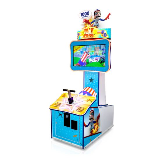
- Page 1 SERVICE MANUAL MINI PLACE SERIAL NUMBER LABEL HERE...
-
Page 2: Factory Contact Information
FACTORY CONTACT INFORMATION BAY TEK ENTERTAINMENT Pulaski Industrial Park 1077 East Glenbrook Drive Pulaski, WI 54162 USA SIGN UP TO RECEIVE OUR E-MAILS! Stay up to date on the latest game information, new products launches, early notification of parts specials, updates of retro fit parts, software upgrades, best practices and more! Visit baytekent.com and enter your email to sign up! You can also register your new game at baytekent.com/register SALES... -
Page 3: Table Of Contents
TABLE OF CONTENTS FACTORY CONTACT INFORMATION ……..…………………………. 2 TABLE OF CONTENTS...……………………………………………….. 3 WELCOME TO Willy Crash Mini ……………………………...………. 4 GAME SPECIFICATIONS ……………………………………………… SAFETY PRECAUTIONS ……………………………………………… GAME SET UP ……………………………………………………..…. 6 - 7 ADJUSTABLE MARQUEE ……..………………………..…………….. AVAILABLE BLANKING PLATES …………………………………….. CARD SWIPE INSTALLATION ……………………………………….. -
Page 4: Welcome To Willy Crash Mini
WELCOME TO WILLY CRASH MINI GAME INSPECTION Please inspect the game for any damaged, loose, or missing parts. If damage is found, please contact your freight carrier first. Then, contact Bay Tek Entertainments’ Service Department at (920) 822-3951 Ext. 1102 Or email us at service@baytekent.com for further assistance. -
Page 5: Game Specifications
GAME SPECIFICATIONS WEIGHT POWER REQUIREMENTS NET WEIGHT 300 lbs. 136 kg SHIP WEIGHT 345 lbs. 157 kg INPUT VOLTAGE 115 VAC 230 VAC GAME DIMENSIONS INPUT FREQUENCY 60 Hz 50 Hz WIDTH 34 1/2” 88 cm DEPTH 48" 122 cm MAX OPERATING CURRENT HEIGHT 96"... -
Page 6: Game Set Up
WILLY CRASH MINI GAME SETUP The game will arrive on one pallet. Please inspect the pallet for shipping damage and report immediately to the freight company if any damage is found. Unbox the pallet and remove the cardboard box from the top of the player console. - Page 7 WILLY CRASH MINI GAME SETUP Install marquee by feeding light power cable through the hole in the top of the cabinet as the marquee is placed on top of the game. Remove the 3 bolts, lock washer, and washers from the hardware kit.
-
Page 8: Adjustable Marquee
ADJUSTABLE MARQUEE 96” The marquee artwork can be removed to accommodate a lower ceiling height. Remove Willy to lower game to 81 inches 81” AVAILABLE BLANKING PLATES A5PL4200 DBA Plate for 12V Upstacker Bill Acceptor A5PL9998 Plate used instead of Coin Mechanisms A5PL8900 Plate used for Bill Validator A5PL9995 Plate used instead of ticket dispenser... -
Page 9: Card Swipe Installation
CARD SWIPE SYSTEM INSTALLATION The Willy Crash game is pre-wired with a UCL (Universal Card Link) connector to accept Card Swipe systems from many different manufactures. Please follow these instructions to make full use of this capability. This would normally plug Option #1: into coin mechanism. -
Page 10: How To Play
HOW TO PLAY Time your launch to shoot Willy into the air, aiming to land on a building. Press plunger down to launch Willy from the cannon! Collect tickets! -
Page 11: Main Menu Functions
MAIN MENU FUCTIONS The Menu and Menu Select buttons are located inside the front door. Hold the MENU button down for 1 second to open the main menu on the monitor. Press MENU to scroll through the options, and MENU SELECT to change the settings. MAIN MENU Clear Tickets Press the MENU SELECT button 3 times to... -
Page 12: Volume & Attract
VOLUME AND ATTRACT MENU Scroll through the options by pressing the “MENU” button. Change selection with the “SELECT” button. Scroll to “BACK” and press the “SELECT” button to go back to the main menu. Default settings are highlighted in yellow below. ATTRACT VOLUME Sets the volume level of the attract loop when the game is not being played. -
Page 13: Game Settings
GAME SETTINGS MENU Scroll through the options by pressing the “MENU” button. Change selection with the “SELECT” button. Scroll to “BACK” and press the “SELECT” button to go back to the main menu. Default settings are highlighted in yellow below. GAME MODE Tickets Points... -
Page 14: Payout Settings
PAYOUT MENU Scroll through the options by pressing the “MENU” button. Change selection with the “SELECT” button. Scroll to “BACK” and press the “SELECT” button to go back to the main menu. Default settings are highlighted in yellow below. CREDITS Sets the amount of credit pulses needed to start a game. -
Page 15: Ticket Patterns
TICKET PATTERNS These are estimates of Average Tickets per Game using the shown ticket values for building and alleys. Change ticket values in the “Payout Menu” to change your individual payout percentages. Pattern Pattern Pattern Pattern Pattern Pattern Pattern Bonus Building 1000 1500 1000... -
Page 16: Game Statistics
GAME STATISTICS MENU Scroll through the options by pressing the “MENU” button. Change selection with the “SELECT” button. Scroll to “BACK” and press the “SELECT” button to go back to the main menu. Default settings are highlighted in yellow below. TOTAL GAMES Reports the actual games played since last reset TOTAL TICKETS... -
Page 17: Diagnostics
DIAGNOSTICS MENU Scroll through the options by pressing the “MENU” button. Change selection with the “SELECT” button. Scroll to “BACK” and press the “SELECT” button to go back to the main menu. Default settings are highlighted in yellow below. PLUNGER INPUT Blinks ON when plunger is down, and sensor beam is blocked. -
Page 18: Dipswitch Settings
DIPSWITCH SETTINGS DESCRIPTION SWITCH SHOW GAME Does not dispense tickets and clears all accumulated credits AMUSEMENT ONLY Does not dispense tickets NJ LOCKOUT Saves tickets owed and unused credits after a power loss 1/2 TICKET PAYOUT Dispenses 1/2 the amount of tickets as shown on screen. It will round up odd amounts of tickets DISABLES LOW TICKET INPUT Note:... -
Page 19: Circuit Board Layout
CIRCUIT BOARD LAYOUT MINI AACB5156 Power Dist. Board CE8006 CE8014 CE8015 A5CEAU010 AACB9600A Audio Cable AACE8016 Audio Amplifier Power to 8001 Board CE8015 AACE8001 Speakers AACE8015 CE19003 12 VDC In AACE8008 Monitor AACE8014 AACE8004 AACE8006 Edge LED’s Power in from DBA Cable Coin Mech Power Dist Bd... -
Page 20: Wiring Diagrams
WIRING DIAGRAM COIN MECH, MENU AND COUNTER Coin Switches and Lights Red is 12 Volts DC White is Coin Up Signal Black is Ground AACBL4A-DOOR To 12 Volt Bill Acceptor Part # A5AC9101 AACE8006 AACE8006 Power In from Power UCL Connector Distribution AACE8014 Card Swipe system cable would be... - Page 21 WIRING DIAGRAM SPEAKERS AND MOTHERBOARD COMMUNICATION Speaker AACE8811A 3.3 Ohms 32” TV A5MO0032B Could be used as a Used 2nd sound channel. AACE8001 A5CORD36 HDMI Cable to Monitor A5CB8000 Graphics Card AAMB10-HD A5CEAU010 AACB9600A Audio Jack from Amplifier Audio Amplifier Board to Audio Filter cable AACE8015...
- Page 22 WIRING DIAGRAM SENSORS AND LEDS AACE19006 Monitor Surround Led’s AACE8008 The LED on the sensor is normally off. It comes On when blocked to launch cannon. AACB8001 AACB3850A Light Board Plunger Sensor Blue Red & Yellow LED Connectors is ON when board is communicating to the motherboard via USB cable...
- Page 23 WIRING DIAGRAM AC IN AND POWER SUPPLY 7 Watt 7 Watt Power In Cord AC Bulb AC Bulb 32” TV From Wall A5LI0004 A5LI0004 A5MO0032B A5CORD5 Line Filter Special Power AC Bleeder Board A5FI9010 Cord included AACB15001 with TV AACE19004 AACE19001 AACE19002 A5CORD5000...
-
Page 24: Troubleshooting Guide
TROUBLESHOOTING GUIDE Troubleshooting Strategy Use common sense and a systematic method of troubleshooting to determine the exact problem, probable cause and remedy. Use the process of elimination to find the faulty component. Always check for the simple and obvious causes first such as unplugged, loose or broken wires and bad sensors, bent, pinched, stuck or jammed components. - Page 25 TROUBLESHOOTING GUIDE Problem Probable Cause Remedy Check for I/O board USB Refer to “I/O Aux Board Issue” diagnostic Section. cable communication. Check coin switches—both should be wired normally Game not coining Ensure game makes sound open. If one switch is “closed” the other will not work when coin switch is either.
- Page 26 TROUBLESHOOTING GUIDE Problem Probable Cause Remedy Opto Sensor on ticket Blow dust from sensor and clean with Tickets do dispenser dirty. isopropyl alcohol. not dispense Faulty ticket dispenser. Replace with working dispenser to isolate the or Wrong Tickets on problem. (A5TD1) amount monitor does not match...
- Page 27 TROUBLESHOOTING GUIDE Problem Probable Cause Remedy Monitor HDMI cable unplugged from video card. (A5CORD36) Monitor shows “No The game will not boot up with the monitor disconnected Signal” Monitor not working. Faulty or loose RAM on motherboard Large power connector unplugged on motherboard AAMB10-HD Power down, Small power connector unplugged on motherboard...
-
Page 28: Power Supply Diagnostics
POWER SUPPLY DIAGNOSTICS 1.) Verify AC power to game. Check power strip in front door. The rocker switch should be illuminated. 2.) Check connection to power supply. 3.) Ensure Power Supply switch is set to 115V (or 230V) (Some model power supplies may not have this) 4.) Ensure Power switch is on. -
Page 29: Bill Acceptor Diagnostics
BILL ACCEPTOR DIAGNOSTICS Note: There are many different models and brands of Bill Acceptors that are used on redemption games. Your Bill Acceptor may differ from the unit shown. Standard DBA is MEI # AE2454-U5E Part # A5AC9101 Only use 12 Volt DC Bill Acceptor Determine if Bill Acceptor has power: Turn game ON—The bill acceptor should make noise as stacker cycles and green lights on outside bezel should flash. -
Page 30: How To Remove Monitor
HOW TO REMOVE MONITOR Tools Needed: # 2 Square bit screwdriver Philips Screwdriver bit 7/16” Wrench 2 people MINI Instructions: Unplug the game’s power cord from the wall. Unlock and remove the upper back door of the game, Remove the 2 screws using a # 2 square bit, and remove the wood block . - Page 31 HOW TO REMOVE MONITOR Remove Monitor from Housing: Remove the 18 screws using a # 2 square bit from the perimeter of the wood housing. Save for later installation. Remove the 4 Phillips bolts, washers, and spacers in the center that are supporting the monitor.
-
Page 32: Monitor Settings
MONITOR SETTINGS The 32” Full HDTV used in Willy Crash includes a remote control to access the menu. - Set screen options as shown:... -
Page 33: Handle Assy Exploded View
HANDLE ASSY EXPLODED VIEW A5CO4400 AAME4415 Screws are A5SCSQ001 WARR9824 (8 per assembly) A5ME4414-BLK A5BOCG090 A5BOPH220 A5WAFL030 A5NUNY050 A5NULO050 A5BRZN010 A5NUNY050 A5HKSY020 WARR9824 A5SP1801 WACA8003 A5WAFL050 WACA8003 A5SCHX016 A5WAFL050 A5NUNY070 A5RICZ010 A5SENY071 A5SENY170 A5PICV030... -
Page 34: Parts List
PARTS LIST PART # DESCRIPTION PART # DESCRIPTION AABK1013 Bracket, Pushbutton/Counters A5CORD5 Cord, Ac Computer Cord, 6.5' A5BK9999 Bracket, Power Supply Mounting A5CORD5000 Cord, Power Adapter, 1ft A5BURU075 Bumper, Rubber,2 ¼ X 2 5/8, Black A5CORD58 Cable, USB, Male A To Micro, 3ft A5CA1005 Caster, Swivel/Lock A5CE2300... -
Page 35: Parts Pictures
PARTS PICTURES A5BK1013 A5BK9999 A5BURU075 A5CA1005 A5CB8020 A5CO4400 A5FI9010 A5HO1003 A5LI0004 A5LK2001 A5LK5002 A5OU5000 A5PL4200 A5PL8900 A5PL9998 A5SP1801 AASW200 W5HG1025 W5HG1065 W5KE5000 W5TM4002 A5ME2035 A5ME4182 A5ME4414-BLK AAME4415 A5ME5508 A5RICZ010 A5DE0042 AACE1710 A5DE19000 AACBL4A-DOORA A5CORD36 A5CORD5 A5CE2300 A5CEAU010 AACE8001 AACE8002 AACE8003 AACE8004 AACE8005 AACE8006... - Page 36 PARTS PICTURES A5PS1013 A5TD1 AACB9600A AACB5156 AACB3850A AAMB10-HD AACB9604A AACB8001...
-
Page 37: Decal Diagram
DECAL DIAGRAM... -
Page 38: Maintenance Log
REPAIR/MAINTENANCE LOG If you need to make repairs or order replacement parts it is a good idea to keep a log. Below is a chart you can use to track repairs and maintenance. DATE MAINTENANCE PERFORMED PARTS ORDERED MISC. NOTES... -
Page 39: Technical Support
TECHNICAL SUPPORT Excellent customer service is very important to Bay Tek Entertainment! We know that keeping your games in great operating condition is important to your business. When you need us, we are here to help. You can call us for free technical assistance, and you can count on us to have parts on-hand to support your game. -
Page 40: Warranty
WARRANTY OPTIONS Bay Tek Entertainment warrants to the original purchaser that the game will be free of defects in workmanship and materials for a period of 6 months from the date of installation. Register your new game for an extra 3 months on your warranty. Log on to : http://www.baytekent.com Then click on the Register tab.
Need help?
Do you have a question about the Willy Crash Mini and is the answer not in the manual?
Questions and answers