Advertisement
Quick Links
Advertisement

Related Manuals for Lockly DEADBOLT EDITION SECURE PGD728


Summary of Contents for Lockly DEADBOLT EDITION SECURE PGD728
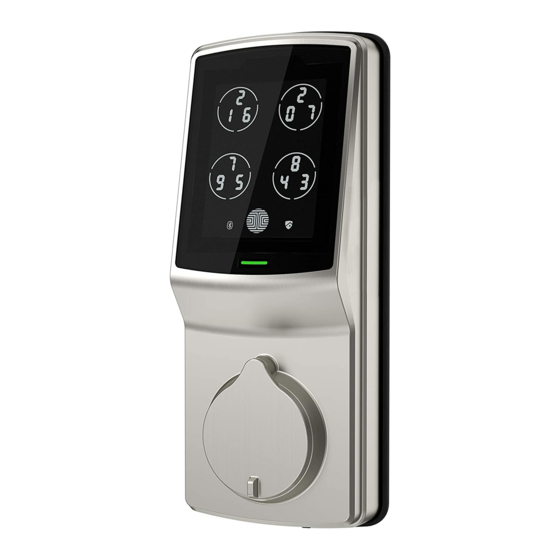
- Page 1 DEADBOLT EDITION SECURE ® INSTALLATION MANUAL...
- Page 2 Plate PM4*12MM (Optional) Screw Exterior Assembly PM5×60mm Screw Keys Deadbolt LOCK SERIAL PGDXXXXXXXXX ACTIVATION CODE XXXXXXXX SCAN & SAVE Dust Box Strike Plate KA4*20MM Screw Lockly Secure can be fitted for both right swing doors and left swing doors. ®...
- Page 3 STEP 1. PREPARE DOOR FOR INSTALLATION 1.1 To complete installation, you would need the following: Flathead Screwdriver Phillips Screwdriver Ruler 1.2 Prepare door and remove existing lock. If necessary, use provided Installation Template to prepare door. 2-⅜" (60mm) or 2-¾" (70mm) 1-⅜"...
- Page 4 STEP 2. ADJUST DEADBOLT AND INSTALL 2.1 Deadbolt slit hole must be aligned to the center of the door hole. If not adjust as shown below: 2.1.1 Wear gloves during adjustment Deadbolt at 2-3/4" (70mm) to prevent pinching your hands (default shipping status) extend I.
- Page 5 STEP 2. ADJUST DEADBOLT AND INSTALL 2.2 Extend the deadbolt by inserting a 2.3 Insert the Deadbolt to the edge flat head screwdriver on the slit hole or door hole, make sure that its right side by pushing the crank towards the metal up and the slit hole is in vertical position, face plate.
- Page 6 STEP 3. INSTALLING THE EXTERIOR ASSEMBLY 3.1 To secure Exterior Assembly of lock, peel the cover off the adhesive strips Peel paper off the Adhesive tape *This hole (O) is for the optional Slotted Barrel Extension provided for stabilizing your lock. It will require drilling extra hole on your door (See template as provided).
- Page 7 STEP 4. INSTALLING THE INTERIOR ASSEMBLY (F) 4.1: Check the mounting plate 4.2: Place the mounting plate on the alignment to your door hole before interior side of the door. Guide the cable you peel of the cover off the to the opening ear on the side of mounting adhesive strip.
- Page 8 STEP 5. INSTALLING THE INTERIOR ASSEMBLY (F) 5.1 Plug the cable that is coming through the door into the Interior lock. Make sure you match the direction of the plug correctly and matching the red side of the plug with the red side on the lock.
- Page 9 STEP 5. INSTALLING THE INTERIOR ASSEMBLY (F) 5.3 Place the interior assembly against the 5.2 Before placing the interior mounting plate and make sure the torque assembly to the mounting plate, blade is inserted to the thumb turn shaft. ensure the thumb turn is vertical. MAKE SURE IT IS IN THE Torque Blade Thumb turn shaft...
- Page 10 First install 3 of the 4 batteries. Before installing the last battery, press and hold the PROGRAM button while installing the last battery until you hear a beep from Lockly ® Lockly will then perform a self check and the ®...
- Page 11 STEP 7. INSTALLATING DOOR STRIKE Install the door strike. Install the door strike to your door frame and proceed to the last step of installation of your new lock. You may use our supplied door strike or use your existing door strike as long as the deadbolt moves smoothly in and out of the door strike.
- Page 12 STEP 8. DOWNLOAD LOCKLY ® Congratulations! You have completed the Lockly Secure physical lock installation. To com- ® plete your setup, download the Lockly app from the iOS or Google Play app Store and ® follow on-screen instructions. Scan or visit Lockly.com/app...
- Page 13 SECURE LINK PGH200 You can add live status monitoring and voice control capabilities to your Lockly Smart Lock with ® Amazon Alexa or Google Assistant via installing the Secure Link Wi-Fi Hub and Door Sensors (Sold Separately) Know it’s Closed.
- Page 14 Certified FCC Warning: This device complies with Part 15 of the FCC Rules. Operation is subject to the following two conditions: (1) This device may not cause harmful interference, and (2) this device must accept any interference received, including interference that may cause undesired operation. NOTE 1: This equipment has been tested and found to comply with the limits for a Class B digital device, pursuant to part 15 of the FCC Rules.
- Page 15 (1) This device may not cause interference. (2) This device must accept any interference, including interference that may cause undesired opera- tion of the device. L’émetteur/récepteur exempt de licence contenu dans le présent appareil est conforme aux CNR d’Innovation, Sciences et Développement économique Canada applicables aux appareils radio exempts de licence.
- Page 16 ® SECURE We’re here to help! help@lockly.com https://lockly.com/help IMPGD728200505...
- Page 17 ® SECURE For the latest version of this manual, please visit the link below: http://lockly.com/help...
Need help?
Do you have a question about the DEADBOLT EDITION SECURE PGD728 and is the answer not in the manual?
Questions and answers