Oriental motor BLH Series User Manual
Brushless motor rs-485 communication type
Hide thumbs
Also See for BLH Series:
- Operating manual (68 pages) ,
- Operating manual (40 pages) ,
- Operating manual (24 pages)
Table of Contents
Advertisement
HP-5113
Brushless Motor
BLH Series
RS-485 communication type
USER MANUAL
Thank you for purchasing an Oriental Motor product.
This Operating Manual describes product handling procedures and safety precautions.
• Please read it thoroughly to ensure safe operation.
• Always keep the manual where it is readily available.
Advertisement
Table of Contents

Subscribe to Our Youtube Channel
Related Manuals for Oriental motor BLH Series


Summary of Contents for Oriental motor BLH Series
- Page 1 BLH Series RS-485 communication type USER MANUAL Thank you for purchasing an Oriental Motor product. This Operating Manual describes product handling procedures and safety precautions. • Please read it thoroughly to ensure safe operation. • Always keep the manual where it is readily available.
-
Page 2: Table Of Contents
Table of contents Introduction ............4 Parameter ............30 Parameter list ............31 Safety precautions ..........5 Operation data extension setting ....35 Precautions for use ..........6 Operation and I/O action ........39 Preparation ............7 Alarm and information settings ......41 Checking the product ........... 7 Monitor setting .............44 How to identify the product model .... - Page 3 12 Addresses and codes list ....... 97 12.1 Timing for parameter to update .....97 12.2 I/O commands ............98 12.3 Group command ..........98 12.4 Protect release commands .......99 12.5 Maintenance commands ........99 12.6 Monitor commands .......... 100 12.7 Operation data commands ......109 12.8 Parameter commands ........
-
Page 4: Introduction
Do not use for any other purpose. For the power supply, use a DC power supply with reinforced insulation on its primary and secondary sides. Oriental Motor Co., Ltd. is not responsible for any damage caused through failure to observe this warning. -
Page 5: Safety Precautions
Safety precautions 2 Safety precautions The precautions described below are intended to ensure the safe and correct use of the product, and to prevent the user and other personnel from exposure to the risk of injury. Use the product only after carefully reading and fully understanding these instructions. -
Page 6: Precautions For Use
Precautions for use 3 Precautions for use This chapter covers limitations and requirements the user should consider when using the product. Be sure to match the output power of the driver with that of the motor when using. z Notes for continuous regeneration operation When regeneration operation is continuously performed, check the following conditions are satisfied before use. -
Page 7: Preparation
□ Driver ..........1 unit □ OPERATING MANUAL ....1 copy 4.2 How to identify the product model BLH2D 30 - K R ① Driver type BLH2D: BLH Series driver ② Output power 15: 15 W 30: 30 W 50: 50 W ① ②... -
Page 8: Names And Functions Of Parts
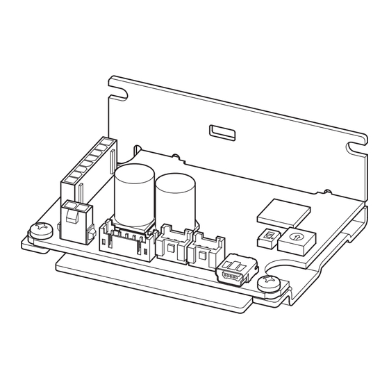
Preparation 4.5 Names and functions of parts This section explains the name and function for each part of the driver. Termination resistor switch (TERM.) Motor connector (CN3) Address number setting switch (ID) TERM. C-DAT C-ERR PWR/ALM Power supply connector (CN1) USB connector (CN4) LED (PWR/ALM) RS-485 communication connector (CN5) -
Page 9: Installation
Installation 5 Installation 5.1 Installation location The driver is designed and manufactured to be incorporated in equipment. Install it in a well-ventilated location that provides easy access for inspection. The location must also satisfy the following conditions: • Inside an enclosure that is installed indoors (provide vent holes) •... -
Page 10: Connection
Connection 6 Connection This chapter explains how to connect the driver with the motor, power supply, and I/O signals. 6.1 Connecting the motor and driver (CN3) Insert the motor cable connector into the motor connector (CN3) on the driver. When extending the motor cable, use a connection cable (sold separately). The maximum extension distance including the cable length of the motor itself should be 2 m (6.6 ft.). -
Page 11: Connecting The I/O Signals (Cn2)
Connection Note on power ON/OFF using a mechanical contact • When turning on or off the power supply using a mechanical contact (breaker, electromagnetic switch, relay, etc.), do so only the positive side (+) of the power supply using the mechanical contact. -
Page 12: Driver I/O Circuit
Connection 6.4 Driver I/O circuit „ Input signals circuit „ Driver internal circuit Input signals of the driver are C-MOS inputs. +5 V The signal state represents "ON: 0 to 0.5 V (L level)" and "OFF: 4 to 5 V (H level)." 10 kΩ... -
Page 13: Connecting External Analog Setting Devices
Connection 6.5 Connecting external analog setting devices Using an external potentiometer (sold separately), external DC voltage, or PWM signal input, the rotation speed or the torque limiting value can be set. „ Using an external potentiometer „ Connect to the pin Nos. 4 to 6 of the CN2. External potentiometer PAVR2-20K (sold separately) -
Page 14: Grounding
Connection 6.6 Grounding The wire used to ground the motor and driver must be as thick and short to the grounding point as possible so that no potential difference is generated. Choose a large, thick and uniformly conductive surface for the grounding point. z Grounding the motor z Grounding the driver Connect the grounding wire along with a set... -
Page 15: Connecting The Rs-485 Communication Cable (Cn5, Cn6)
Connection 6.8 Connecting the RS-485 communication cable (CN5, CN6) Connect this cable when controlling the driver via RS-485 communication. Connect the RS-485 communication cable to the CN5 connector or the CN6 connector on the driver. The vacant connector can be used to connect a different driver. RS-485 communication cables for connection (sold separately) are available. -
Page 16: Connection Diagram
6.9 Connection diagram A connection example of I/O signals with a programmable controller are as shown below. The I/O signals circuit of the BLH Series RS-485 communication type are configured with current SINK logic. (Current SOURCE logic is not supported.) -
Page 17: Noise Elimination Measures
„ About power supply „ The BLH Series is a product of DC power supply input. Use a DC power supply (such as a switching power supply) that optimally conforms to the EMC Directive. „ Connecting the motor cable „... - Page 18 Connection „ Notes about installation and wiring „ • Connect the motor, driver and other peripheral control equipment directly to the grounding point so as to prevent a potential difference from developing between grounds. • When relays or electromagnetic switches are used together with the system, use noise filters and CR circuits to suppress surges generated by them.
-
Page 19: Operation Data
Operation data 7 Operation data This chapter describes operations that can be performed with the BLH Series RS-485 communication type. 7.1 Setting the operation data Data required to operate the motor is as follows. Data name Description Rotation speed The motor rotation speed can be set. -
Page 20: Setting The Rotation Speed
Operation data 7.2 Setting the rotation speed Setting method Digital External analog setting device/PWM signal input Host 0 to 5 VDC controller 1 mA or more MEXE02 or RS-485 communication External potentiometer External DC voltage PWM signal The setting method for each operation data number can be changed using the MEXE02 or RS-485 communication. If the external analog setting device/PWM signal input is selected in the setting method, set whether to set the operation data with the external analog setting device (external potentiometer, external DC voltage) or the PWM signal input using the "External setting method"... - Page 21 Operation data „ Using an external potentiometer „ An external potentiometer is used to set the speed. PAVR2-20K Use the PAVR2-20K (sold separately) for an external potentiometer. Setting range: 0, 80 to 3150 r/min HIGH External potentiometer - External potentiometer Rotation speed characteristics PAVR2-20K (representative values)
-
Page 22: Setting The Acceleration Time And Deceleration Time
Operation data 7.3 Setting the acceleration time and deceleration time The acceleration time and the deceleration time can be set so that an impact is not applied to a load when the motor is started or stopped. The actual acceleration time and deceleration time vary depending on the conditions of use, load inertia, or load torque specified by the customer. - Page 23 Operation data „ TLC output „ When the motor output torque is limited, the TLC output is turned ON. If the motor is operated at low speed or the torque limiting value is set to less than 20%, the TLC output may not be Note stable.
- Page 24 Operation data „ Using an external potentiometer „ When the torque limiting value is set using an external potentiometer, use the PAVR2-20K PAVR2-20K (sold separately). Setting range: 0 to 200% HIGH External potentiometer - External potentiometer Torque limiting value characteristics PAVR2-20K (representative values) (sold separately)
-
Page 25: Example Of Operation Pattern
Operation data 7.5 Example of operation pattern The figure shows an example when operation is performed using direct I/O after setting 2000 r/min to the operation data No.0 and 650 r/min to the operating data No.1 in the 3-wire mode. The rotation direction shows the round shaft type. -
Page 26: Multi-Motor Control
Operation data 7.7 Multi-motor control Operating two or more motors at the same speed can be performed using an external potentiometer or external DC voltage. Using an external potentiometer Use common lines for the power supply and speed setting, and set the speed using VRx as shown in the figure below. •... -
Page 27: Guidance
Guidance 8 Guidance If you are new to this product, read this chapter to understand the operating methods along with the operation flow. This is an example how to set operation data and parameters to the driver and operate the motor using a host controller. •... - Page 28 Guidance STEP2 Setting switches Set the termination resistor and the address number with the switches. Turn off the driver power before setting the switches. If the switches are set while the power is still on, the new switch Note settings will not be enabled. Termination resistor switch (TERM.) TERM.
- Page 29 Guidance STEP4 Turning on the power supply again The address number setting switch and the communication parameters of the driver will be updated after turning on the power supply again. STEP5 Operating the motor Send a message to operate the motor. As an example, this section explains how to perform the following operation. Rotation speed 2500 r/min Time...
-
Page 30: Parameter
Parameter 9 Parameter Operation data and parameters are set using the MEXE02 or RS-485 communication. Operation data and parameters having set are saved in the RAM or non-volatile memory. The parameters in the RAM are erased once the power supply is shut off, but the parameters in the non-volatile memory are remained to store even if the power supply is shut off. -
Page 31: Parameter List
Parameter 9.1 Parameter list Reference Parameter name Setting range Factory setting Update page Speed upper limit 80 to 3150 r/min 3150 Speed lower limit 80 to 3150 r/min Torque limiting maximum value 0 to 200% 0: External analog setting device External setting method 1: PWM signal input P.35... - Page 32 Parameter Reference Parameter name Setting range Factory setting Update page INFO action (Driver temperature information (INFO-DRVTMP)) INFO action (Overvoltage information (INFO-OVOLT)) INFO action (Undervoltage information (INFO- UVOLT)) INFO action (Load information (INFO-LOAD)) INFO action (Speed information (INFO-SPD)) INFO action (Operation data setting error information (INFO-SET-E)) INFO action (Operation prohibited information (INFO-DRV))
- Page 33 Parameter Reference Parameter name Setting range Factory setting Update page R-IN0 input function selection 64: M0 R-IN1 input function selection 65: M1 R-IN2 input function selection 66: M2 R-IN3 input function selection 58: FWD (START/STOP) R-IN4 input function selection 59: REV (RUN/BRAKE) R-IN5 input function selection 72: STOP-MODE (FWD/REV) R-IN6 input function selection...
- Page 34 Parameter Reference Parameter name Setting range Factory setting Update page 0: Not monitored RS-485 communication timeout alarm 1 to 10000 ms 0: Disable RS-485 communication error alarm 1 to 10 times Transmission waiting time 0.0 to 1000.0 ms 0.0: Set automatically Silent interval 0.1 to 10.0 ms 0: Normal response is...
-
Page 35: Operation Data Extension Setting
Parameter 9.2 Operation data extension setting Using the operation data extension setting, functions or settings for the rotation speed and the torque limiting can be changed. A: Update immediately, B: Update after operation stop, C: Update after executing Configuration Factory Parameter name Description Setting range... - Page 36 Parameter Speed lower limit Set the lower limit value of the rotation speed with the "Speed lower limit" parameter. If the rotation speed below the "Speed lower limit" is already set in the operation data, the rotation speed is limited to the value set in the "Speed lower limit"...
- Page 37 Parameter „ External setting method „ This parameter is used to select the external analog setting device (external potentiometer or external DC voltage) or PWM signal input. The external analog setting device is set at the time of shipment. Selecting the PWM signal input and inputting the PWM signal can also set the rotation speed or the torque limiting value.
- Page 38 Parameter „ External analog torque limiting gain, External analog torque limiting offset „ If gain and offset are adjusted when the torque limiting value is set using the external analog setting device, the slope of the torque limiting value command can be changed, and the torque limiting value can finely be adjusted. Note The torque limiting value corresponding to the voltage value varies depending on the product.
-
Page 39: Operation And I/O Action
Parameter 9.3 Operation and I/O action A: Update immediately, B: Update after operation stop, C: Update after executing Configuration Factory Parameter name Description Setting range Update setting 0: No filter This is a function to suppress an impact being applied to a load at starting Impact softening filter 1: Filter 1 or stopping. - Page 40 Parameter „ Motor rotation direction „ Even when a gearhead with a gear ratio which rotation direction is opposite to the motor output shaft is used, the rotation direction of the gearhead output shaft when the FWD/REV input * is turned ON can be set to the same as that of the motor. Rotation direction of the motor output shaft ⇒...
-
Page 41: Alarm And Information Settings
Parameter 9.4 Alarm and information settings Refer to p.137 for details about alarms. Refer to p.141 for details about information. A: Update immediately, C: Update after executing Configuration Parameter name Description Setting range Factory setting Update Sets the detection time of the overload Overload alarm detection time 0.1 to 10.0 s 10.0... - Page 42 Parameter A: Update immediately Factory Parameter name Description Setting range Update setting INFO action (Driver temperature information (INFO-DRVTMP)) INFO action (Overvoltage information (INFO- OVOLT)) INFO action (Undervoltage information (INFO- UVOLT)) INFO action (Load information (INFO-LOAD)) INFO action (Speed information (INFO-SPD)) INFO action (Operation data setting error information (INFO-SET-E)) INFO action (Operation prohibited information...
- Page 43 Parameter „ Overload alarm detection time „ The "Overload alarm detection time" parameter is used to change the time after the motor output torque exceeded the overload detection level until the overload alarm is detected. The overload alarm is generated if a load exceeding the rated torque was applied to the motor for the time set in the "Overload alarm detection time"...
-
Page 44: Monitor Setting
Parameter 9.5 Monitor setting A: Update immediately Parameter Setting Factory Description Update name range setting Driver user The desired name can be given to the driver used. Up to 16 – name (The set name can be checked using the unit information monitor.) characters Speed Sets the speed reduction ratio when the rotation speed of the gearhead output... -
Page 45: Direct-In Function Selection, Direct-Out Function Selection
Parameter 9.6 Direct-IN function selection, Direct-OUT function selection C: Update after executing Configuration Parameter name Description Setting range Factory setting Update D-IN0 input function selection 58: FWD (START/STOP) D-IN1 input function selection 59: REV (RUN/BRAKE) Selects the input signal to assign to D-IN2 input function selection Refer to p.58. -
Page 46: Communication And I/F Function
Parameter 9.8 Communication and I/F function A: Update immediately, C: Update after executing Configuration, D: Update after turning on the power again Factory Parameter name Description Setting range Update setting Sets whether to enable or disable the USB-ID (serial number). When it is set to 0: Disable USB-ID enable "Disable,"... - Page 47 Parameter A: Update immediately Setting Parameter name Description Factory setting Update range Indirect reference address setting (0) 576: Operation data No.0 rotation speed Indirect reference address setting (1) 896: Operation data No.0 torque limiting value Indirect reference address setting (2) 768: Operation data No.0 acceleration time Indirect reference address setting (3) 832: Operation data No.0 deceleration time...
- Page 48 Parameter „ USB-ID „ The USB-ID is a parameter to associate the USB port (COM port number) of a PC with the driver. The COM port number is used when setting the communication port with the MEXE02. If multiple drivers are connected to a PC, the PC allocates empty COM ports to the driver in the connected order. If the driver power is turned on again or if the UBS cable is removed and inserted, the allocated COM port numbers may change because the order of connection recognized by the PC is changed.
- Page 49 Parameter „ RS-485 Receive packet monitor „ This is a parameter to select the target to be monitored with the RS-485 communication monitor of the MEXE02. Either "All" (entire communication) or "Only own address" can be selected. „ Communication ID „...
- Page 50 Parameter „ Transmission waiting time „ This is a parameter to set the transmission waiting time. The transmission waiting time is a time after the slave switches its communication line to the transmission mode upon receiving a query from the master, until it starts sending a response (The actual transmission waiting time corresponds to the silent interval (C3.5) plus the value set in the "Transmission waiting time"...
- Page 51 Parameter „ Slave error response mode „ Sets the response when the slave error occurred. If the slave error occurs, an exception response is returned at the factory setting. When no exception response is required as in the case of a touch panel, set to "0: Normal response is returned".
- Page 52 Parameter „ Indirect reference address „ The indirect reference address is a parameter to set an address of data that is desired to set by indirect reference (input a half value of the register address (upper) to be set). Indirect reference is one of the setting method of a query. When addresses of data are not successive, multiple commands can be executed with one query by using indirect reference.
-
Page 53: I/O Signals Assignment List
Parameter 9.9 I/O signals assignment list To assign signals via RS-485 communication, use the "Assignment number" in the table instead of the signal names. „ Input signal „ Assignment Assignment Assignment Signal name Signal name Signal name number number number Not used FWD (START/STOP) ALM-RST... -
Page 54: O Signals
I/O signals 10 I/O signals This manual describes I/O signals as follows. • Direct I/O: I/O to be accessed via I/O signal connector (CN2) • Remote I/O: I/O to be accessed via RS-485 communication 10.1 Direct I/O Direct I/O is I/O that the I/O signal cable is connected to the I/O signal connector (CN2) to input and output signals directly. - Page 55 I/O signals „ Changing the logic level setting of input signals „ The logic level setting for the direct input can be changed. Parameter Description Setting range Factory setting D-IN0 input logic level setting 0: Not invert Changes the logic level setting for the direct input (D-IN0 to D-IN4). 1: Invert D-IN4 input logic level setting In the case of the factory setting (setting is "Not invert"), the driver recognizes that an internal signal is ON (active state)
-
Page 56: Remote I/O
I/O signals 10.2 Remote I/O Remote I/O is I/O to be accessed via RS-485 communication. „ Assignment to input signals „ The following signals are assigned at the time of shipment. Input signals assigned to the remote inputs R-IN0 to R-IN15 can be changed using parameters. - Page 57 I/O signals „ Assignment of output signals „ The following signals are assigned at the time of shipment. Output signals assigned to the remote outputs R-OUT0 to R-OUT15 can be changed using parameters. Refer to p.58 for the output signals list that can be assigned. Remote I/O signal name Factory setting Remote I/O signal name...
-
Page 58: Signals List
I/O signals 10.3 Signals list „ Input signals „ Assignment Signal name Description number Not used Set when the input terminal is not used. ALM-RST This is a signal to reset the alarm being generated. (The signal is reset at the ON edge of the input.) INFO-CLR This is a signal to clear the information being generated. - Page 59 I/O signals Assignment Signal name Description number This is a signal to output an alarm status of the driver. ALM-A It is turned ON when an alarm is generated. This is a signal to output an alarm status of the driver. ALM-B It is turned OFF when an alarm is generated.
-
Page 60: Input Signals
I/O signals 10.4 Input signals This section explains each input signal. When input signals are assigned to the direct input, in order to surely recognize the input signal, ensure the ON time Note and OFF time of each input signal for at least 2 ms. Names and functions of the operation input signals vary depending on the setting of the "Operation input mode selection"... - Page 61 I/O signals [2-Wire mode] „ FWD input, REV input „ When the FWD input is turned ON, the motor rotates in the forward direction. When it is turned OFF, the motor stops according to the STOP-MODE input status. When the REV input is turned ON, the motor rotates in the reverse direction. When it is turned OFF, the motor stops according to the STOP-MODE input status.
- Page 62 I/O signals „ ALM-RST input „ The ALM-RST input is a signal to reset an alarm status. (The alarm will be reset at the ON edge of the input.) To reset an alarm, turn the operation input signal OFF, and remove the cause of the alarm before turning the ALM-RST input ON.
-
Page 63: Output Signals
I/O signals „ TL input „ The TL input is a signal to switch whether to enable or disable the torque limiting function. When the TL input is turned ON, the torque limiting function is enabled. The maximum value of the motor output torque is limited based on the set torque limiting value. When the TL input is turned OFF, the torque limiting function is disabled, and the maximum value of the motor output torque will be the peak torque (200%). - Page 64 I/O signals „ TLC output „ When the motor output torque is limited, the TLC output is turned ON. Torque limiting value (%) Load torque TLC output If the motor is operated at low speed or the torque limiting value is set to less than 20%, the TLC output may not be Note stable.
- Page 65 I/O signals „ VA output „ When the feedback speed reached the "plus or minus range of VA detection width with respect to the setting speed," this output is turned ON. A range to turn the VA output ON can be set using the "VA detection width" parameter. Related parameters Parameter name Description...
-
Page 66: General Signals
I/O signals „ Response output „ The response output is a signal to output the ON-OFF status of the corresponding input signal. The table below shows the correspondences between input signals and output signals. Input signals Output signals ALM-RST ALM-RST_R INFO-CLR INFO-CLR_R HMI_R... -
Page 67: Modbus Rtu Control (Rs-485 Communication)
Each slave executes the process requested by query and returns a response message. The BLH Series RS-485 communication type supports the RTU mode only as the transmission mode. The ASC Ⅱ mode is not supported. Under this protocol, messages are sent in one of two methods. - Page 68 Modbus RTU control (RS-485 communication) z Internal input circuit Driver 1 RS-485 ∗1 TERM. 1 kΩ TERM. 120 Ω 1 kΩ Driver 2 TERM. 1 kΩ TERM. 120 Ω 1 kΩ Driver 15 ∗2 ∗2 TERM. 1 kΩ TERM. 120 Ω 1 kΩ...
- Page 69 Modbus RTU control (RS-485 communication) 11.1.2 Communication timing The communication time monitored by the driver and the communication timing of the master are as follows. Tb3 (broadcast) C3.5 C3.5 C3.5 Master Query Query Slave Response Code Name Description Intervals between received queries are monitored. If no query could be received after the time set with the "RS-485 communication timeout alarm"...
-
Page 70: Message Structure
Modbus RTU control (RS-485 communication) 11.2 Message structure The message format is shown below. Master Query Slave Slave address Slave address Response Function code Function code Data Data Error check Error check 11.2.1 Query The query message structure is shown below. Slave address Function code Data... - Page 71 Modbus RTU control (RS-485 communication) z Calculation example of CRC-16 The table shows a calculation example when setting the slave address of the first byte to 02h and the function code of the second byte to 07h. The result of actual CRC-16 calculation is calculated including the data on and after the third byte. Description Result Bit shifted out...
- Page 72 Modbus RTU control (RS-485 communication) 11.2.2 Response Slave-returned responses are classified into three types: normal response, no response, and exception response. The response message structure is the same as the query message structure. Slave address Function code Data Error check 8 bits 8 bits N x 8 bits...
- Page 73 Modbus RTU control (RS-485 communication) z Example of exception response Slave address Query Slave address Function code Function code Register address (upper) Data Exception code Register address (lower) Error check (lower) Number of registers (upper) Response Error check (upper) Number of registers (lower) Data Number of data bytes Value write to register address (upper)
-
Page 74: Function Code
Modbus RTU control (RS-485 communication) 11.3 Function code This section explains the function codes supported by the BLH Series RS-485 communication type driver. Note that the function code cannot be executed if function codes other than those introduced here are sent. - Page 75 Modbus RTU control (RS-485 communication) 11.3.2 Writing to a holding register (06h) This function code is used to write data to a specified register address. However, since the result combining the upper and lower may be outside the data range, write the upper and lower at the same time using the "Writing to multiple holding registers (10h)."...
- Page 76 Modbus RTU control (RS-485 communication) 11.3.3 Diagnosis (08h) This function code is used to diagnose the communication between the master and slave. Arbitrary data is sent and the result of returned data is used to determine whether the communication is normal. 00h (reply to query) is the only sub- function.
- Page 77 Modbus RTU control (RS-485 communication) z Query Field name Data Description Slave address Slave address 4 Function code Writing to multiple holding registers Register address value (upper) Register address to start writing from Register address value (lower) Number of registers (upper) Number of registers to be written from the starting register address (8 registers=0008h) Number of registers (lower)
- Page 78 Modbus RTU control (RS-485 communication) 11.3.5 Read/write of multiple holding registers (17h) With a single function code, reading data and writing data for multiple successive registers can be performed. Data is written first, and then data is read from the specified registers. z Read Data can be read from successive registers of up to 125.
- Page 79 Modbus RTU control (RS-485 communication) z Query Field name Data Description Slave address Slave address 1 Function code Read/write of multiple holding registers (Read) Register address value (upper) Register address to start reading from (Read) Register address value (lower) (Read) Number of registers (upper) Number of registers to be read from the starting register address (4 registers=0004h) (Read) Number of registers (lower)
-
Page 80: Flow Of Setting Required For Modbus Communication
Modbus RTU control (RS-485 communication) 11.4 Flow of setting required for Modbus communication If you are new to this product, read this section to understand the operating methods along with the operation flow. This is an example how to set operation data and parameters to the driver and operate the motor using a host controller. Settings and wirings for the motor and the driver The address number is set with the address number setting switch at the Set address number and transmission rate... -
Page 81: Setting Of Rs-485 Communication
Modbus RTU control (RS-485 communication) 11.5 Setting of RS-485 communication Set parameters required for RS-485 communication before performing communication. Use the MEXE02 to set parameters. 11.5.1 Parameters updated when turning on the power These are parameters related to sending and receiving via RS-485 communication. •... -
Page 82: Data Setting Method
Modbus RTU control (RS-485 communication) 11.6 Data setting method 11.6.1 Overview of setting method There are two methods to set data via Modbus communication. The communication specifications of Modbus allows reading/writing from/to successive addresses when multiple data pieces are handled. Input method Description •... - Page 83 Modbus RTU control (RS-485 communication) „ Addresses and areas of indirect reference „ Indirect reference has 32 addresses and 32 areas (0 to 31). The indirect reference addresses are used only to assign the commands. The address used to read (03h), write (10h), or read/write (17h) the assigned command is that of the corresponding indirect reference area.
- Page 84 Modbus RTU control (RS-485 communication) „ Setting example „ The following is an example of sending data to and receiving data from the address number 1 using indirect reference. z STEP 1: Registration in indirect reference addresses Set data These are values to set in indirect reference. Set a half value of the register address (upper). Register Register Setting...
- Page 85 Modbus RTU control (RS-485 communication) z STEP 2: Writing to indirect reference areas Set data Register address Indirect reference address Data to be sent Setting value Upper Lower ← Indirect reference area 0 1340h 1341h Rotation speed of operation data No.1 (r/min) 2000 (07D0h) ←...
- Page 86 Modbus RTU control (RS-485 communication) z STEP 3: Reading from indirect reference areas Send the following query and read the setting value or monitor set in the indirect reference areas. Query Field name Data Description Slave address Slave address 1 Function code Reading from holding registers Register address (upper)
-
Page 87: Group Send
Modbus RTU control (RS-485 communication) 11.7 Group send With the group send, multiple slaves are made into a group and a query is sent to all slaves in the group at once. The function code that can be executed in the group send is "Writing to multiple holding registers (10h)" only. „... - Page 88 Modbus RTU control (RS-485 communication) z Set by the parameter The setting value of the "Group ID" command is saved in the RAM. In this case, if the power supply is turned off, the setting will be returned to the initial value and the group will be released. Therefore, the group is needed to set again every time after the power supply is turned on.
-
Page 89: Setting Example
Modbus RTU control (RS-485 communication) 11.8 Setting example As an example, this section explains how to perform the following operation. z Setting example • Address number (slave address): 1 • Operation data number: 0 • Rotation speed setting value: 2000 r/min •... - Page 90 Modbus RTU control (RS-485 communication) 2. Send the following query to operate I/O and start an operation in the forward direction. The initial values of remote input are as follows. • Remote input (lower): 125 (007Dh) bit15 bit14 bit13 bit12 bit11 bit10 bit9...
- Page 91 Modbus RTU control (RS-485 communication) 11.8.2 Setting with indirect reference 1. Send the following query to set each operation data of the operation data No.0 and start an operation in the forward direction. • Query Field name Data Description Slave address Slave address 1 Function code Writing to multiple holding registers...
- Page 92 Modbus RTU control (RS-485 communication) 2. To stop the operation, if the following query is sent to turn the START/STOP input OFF, the motor decelerates to a stop. (If the RUN/BRAKE input is turned OFF, the motor stops instantaneously.) • Query (ON-OFF of input signal) Field name Data Description...
-
Page 93: Timing Charts
Modbus RTU control (RS-485 communication) 11.9 Timing charts 11.9.1 Communication start Power-on ∗ 1 s or more Master Query Communication Response Slave P1 "transmission waiting time" parameter + C3.5 (silent interval) 11.9.2 Operation start ∗2 ∗1 Master Query Communication Response Slave ∗3 MOVE output... -
Page 94: Communication Monitor
Modbus RTU control (RS-485 communication) 11.9.5 Configuration ∗2 Master ∗1 Query Query Communication Response Slave ∗5 ∗3 ∗4 Internal processing Internal processing is in progress A message including a query for configuration via RS-485 communication P1 "transmission waiting time" parameter + C3.5 (silent interval) + command processing time C3.5 (silent interval) + 2 ms or less 1 s or less Execute a query after the driver internal processing is completed. -
Page 95: Detection Of Communication Errors
Modbus RTU control (RS-485 communication) 11.11 Detection of communication errors The functions to detect that an error occurs in RS-485 communication are three types including communication errors, alarms, and information. 11.11.1 Communication errors The communication error can be checked using the "Communication error history" command via RS-485 communication or the MEXE02. - Page 96 Modbus RTU control (RS-485 communication) 11.11.3 Alarms related to RS-485 communication If an alarm related to RS-485 communication is generated, the motor will stop operating and the PWR/ALM LED on the driver will blink in red. Alarm code Alarm type Description The RS-485 communication error alarm is generated when the RS-485 communication error consecutively occurs by the number of times set in the "RS-...
-
Page 97: Addresses And Codes List
Addresses and codes list 12 Addresses and codes list 12.1 Timing for parameter to update All data used by the driver is 32-bit wide. The register for the Modbus protocol is 16-bit wide, and one data is described by two registers. When a parameter is set via RS-485 communication, they are saved in the RAM. -
Page 98: I/O Commands
Addresses and codes list 12.2 I/O commands These are commands related to I/O. The set value is saved in the RAM. For the status of remote I/O, direct I/O, and internal I/O, refer to p.104. Modbus communication Register address Name Description Initial value Upper... -
Page 99: Protect Release Commands
Addresses and codes list 12.4 Protect release commands The key code to release the function limitation by the HMI input is set. Write the HMI release key to the target address. Modbus communication Register address Name Description Initial value Upper Lower HMI release key Inputs the key code to release the limitation by the HMI input. -
Page 100: Monitor Commands
Addresses and codes list „ Configuration „ Configuration can be executed when all of the following conditions are satisfied: • An alarm is not present • The motor is not operated • I/O test, teaching/remote operation, and download are not being performed with the MEXE02. The table below shows the driver status before and after configuration is executed. - Page 101 Addresses and codes list Modbus communication Register address Name Description Upper Lower Alarm history 2 (0084h) (0085h) Alarm history 3 (0086h) (0087h) Alarm history 4 (0088h) (0089h) Alarm history 5 (008Ah) (008Bh) Monitors the alarm history. Alarm history 6 (008Ch) (008Dh) Alarm history 7 (008Eh)
- Page 102 Addresses and codes list „ Information related commands „ These are monitor commands related to information. Modbus communication Register address Name Description Upper Lower Information Monitors the information code presently being generated. (00F6h) (00F7h) Monitors the latest information history. 2592 2593 Information history 1 When information is being generated, the information code presently...
- Page 103 Addresses and codes list Modbus communication Register address Name Description Upper Lower 2640 2641 Information time history 9 (0A50h) (0A51h) 2642 2643 Information time history 10 (0A52h) (0A53h) 2644 2645 Information time history 11 (0A54h) (0A55h) 2646 2647 Information time history 12 Monitors the time when information was generated.
- Page 104 Addresses and codes list „ Driver status „ These are monitor commands related to driver status. Modbus communication Register address Name Description Upper Lower Command Speed Monitors the present command speed. (1=1 r/min) (00C8h) (00C9h) Feedback speed Monitors the present feedback speed. (1=1 r/min) (00CEh) (00CFh) Load factor...
- Page 105 Addresses and codes list z Remote output (upper): 126 (007Eh) bit15 bit14 bit13 bit12 bit11 bit10 bit9 bit8 – – – – – – – – bit7 bit6 bit5 bit4 bit3 bit2 bit1 bit0 – – – – – – –...
- Page 106 Addresses and codes list z I/O status 3 (upper): 372 (0174h) bit15 bit14 bit13 bit12 bit11 bit10 bit9 bit8 Reserved Reserved Reserved Reserved Reserved Reserved Reserved Reserved bit7 bit6 bit5 bit4 bit3 bit2 bit1 bit0 Reserved Reserved Reserved Reserved "0" is entered in the reserved field. z I/O status 3 (lower): 373 (0175h) bit15 bit14...
- Page 107 Addresses and codes list z I/O status 7 (upper): 380 (017Ch) bit15 bit14 bit13 bit12 bit11 bit10 bit9 bit8 – – – – – – – – bit7 bit6 bit5 bit4 bit3 bit2 bit1 bit0 – – – – – –...
- Page 108 Addresses and codes list „ Communication related commands „ These are monitor commands related to communication. Modbus communication Register address Name Description Upper Lower Communication error Monitors the communication error code received last time. (00ACh) (00ADh) Communication error history 1 Monitors the latest communication error code history.
-
Page 109: Operation Data Commands
Addresses and codes list 12.7 Operation data commands Operation data that can be set is four items, rotation speed, torque limiting value, acceleration time, and deceleration time. Addresses are grouped for each setting item. Check the indirect reference function if summarized based on the operation data number. - Page 110 Addresses and codes list Modbus communication Register address Name Setting range Initial value Update Upper Lower 1664 1665 Operation data No.0 deceleration time (0680h) (0681h) 1666 1667 Operation data No.1 deceleration time (0682h) (0683h) 1668 1669 Operation data No.2 deceleration time (0684h) (0685h) 1670...
-
Page 111: Parameter Commands
Addresses and codes list 12.8 Parameter commands These commands are used to read or write parameters. All commands can be read and written (READ/WRITE). Refer to p.30 for details about parameters. 12.8.1 Operation data extended setting Modbus communication Register address Name Setting range Initial value Update... - Page 112 Addresses and codes list Modbus communication Register address Name Setting range Initial value Update Upper Lower 0: Disable Load information (034Ch) (034Dh) 1 to 200% 0: Disable Speed information (0344h) (0345h) 1 to 5200 r/min 0: Disable RS-485 communication error information (034Eh) (034Fh) 1 to 10 times...
- Page 113 Addresses and codes list 12.8.4 Monitor setting Modbus communication Register address Name Setting range Initial value Update Upper Lower 4066 4067 Speed reduction ratio 100 to 9999 (0FE2h) (0FE3h) 0: ×1 4076 4077 Speed reduction ratio digit setting 1: ×0.1 (0FECh) (0FEDh) 2: ×0.01...
- Page 114 Addresses and codes list 12.8.7 Remote-IN function setting (R-IN) Modbus communication Register address Name Setting range Initial value Update Upper Lower 4608 4609 R-IN0 input function selection 64: M0 (1200h) (1201h) 4610 4611 R-IN1 input function selection 65: M1 (1202h) (1203h) 4612 4613...
- Page 115 Addresses and codes list 12.8.8 Remote-OUT function setting (R-OUT) Modbus communication Register address Name Setting range Initial value Update Upper Lower 4640 4641 R-OUT0 output function selection 64: M0_R (1220h) (1221h) 4642 4643 R-OUT1 output function selection 65: M1_R (1222h) (1223h) 4644 4645...
- Page 116 Addresses and codes list 12.8.9 Communication and I/F function Modbus communication Register address Name Setting range Initial value Update Upper Lower 0: Disable USB-ID enable (03E4h) (03E5h) 1: Enable USB-ID 0 to 999,999,999 (03E6h) (03E7h) 5110 5111 USB-PID 0 to 31 (13F6h) (13F7h) 5056...
- Page 117 Addresses and codes list Modbus communication Register address Name Setting range Initial value Update Upper Lower 4876 4877 Indirect reference address 103: Feedback speed (130Ch) (130Dh) setting (6) 4878 4879 Indirect reference address 108: Load factor (130Eh) (130Fh) setting (7) 4880 4881 Indirect reference address...
- Page 118 Addresses and codes list 12.8.11 Indirect reference setting (area) Modbus communication Modbus communication Register address Register address Name Name Upper Lower Upper Lower 4928 4929 4960 4961 Indirect reference area (0) Indirect reference area (16) (1340h) (1341h) (1360h) (1361h) 4930 4931 4962 4963...
-
Page 119: I/O Signals Assignment List
Addresses and codes list 12.9 I/O signals assignment list To assign signals via RS-485 communication, use the "Assignment number" in the table instead of the signal names. 12.9.1 Input signals list Assignment number Signal name Monitor target Address Corresponding bit Not used –... - Page 120 Addresses and codes list 12.9.2 Output signals list Assignment number Signal name Monitor target Address Corresponding bit Not used – – – ALM-RST_R bit8 I/O status 1 (lower) (0171h) INFO-CLR_R blt14 HMI_R bit0 TL_R I/O status 1 (upper) bit6 (0170h) EXT-ERROR_R bit9 FWD (START/STOP)_R...
-
Page 121: How To Use Mexe02
How to use MEXE02 13 How to use MEXE02 The MEXE02 is software to set the data required to operate the motor using a PC. Refer to the operating manual of the MEXE02 for how to use such as data editing method and others. 13.1 Starting MEXE02 1. -
Page 122: Setting The Operation Data
How to use MEXE02 13.2 Setting the operation data Click "Operation data" in TreeView. The operation data edit window appears. „ Data entry „ The background color of a cell is initially white. When the value in the cell is changed, the color of the cell changes to yellow. -
Page 123: Setting The Parameters
How to use MEXE02 13.3 Setting the parameters 1. Open the data edit window. 2. Click the parameter group to be edited in TreeView. The parameter edit window appears. Refer to the operating manual of the MEXE02 for how to edit the data and others. 3. -
Page 124: Monitor
How to use MEXE02 13.4 Monitor „ Unit information monitor „ The unit information monitor is provided in the MEXE02. If this monitor function is used, the driver information such as the number of times the main power supply is turned on and the cumulative time of power-on in addition to the product information such as the product name can be checked. - Page 125 How to use MEXE02 „ Status monitor „ The present status of the driver can be monitored. 1. Start the "Status monitor." 2. Click "Start Status monitor." Status monitor starts. 3. To exit the status monitor, unselect "Start Status monitor." z How to view the status monitor window Main monitored items Description...
- Page 126 How to use MEXE02 „ D-I/O, R-I/O monitor „ D-I/O represents direct I/O, and R-I/O represents remote I/O. In addition to the status of I/O signals of the driver, the setting values for the external analog setting device and the PWM signal input can be monitored.
- Page 127 How to use MEXE02 „ Alarm monitor „ The alarm history of the driver can be checked, and also resetting the alarm and clearing the alarm history can be executed. The alarm history can be checked up to 10 items in order of the latest to oldest. 1.
- Page 128 How to use MEXE02 Items that can be checked in the alarm history Item Description Code (Hex) This is a code to represent the content of the generated alarm. Alarm message This is the content of the generated alarm. Driver temperature This is the driver temperature when an alarm was generated.
- Page 129 How to use MEXE02 „ RS-485 communication monitor „ Received data via RS-485 communication can be checked, and also communication error history can be monitored. The communication error history can be checked up to 10 items in order of the latest to oldest. All packets are monitored by the RS-485 communication monitor at the factory setting, but the target to be monitored can be restricted by changing the "RS-485 Receive packet monitor"...
- Page 130 How to use MEXE02 „ Waveform monitor „ The motor rotation speed or the status of I/O signals can be checked in a waveform format. Refer to the operating manual of the MEXE02 for the procedures to operate the applicable products using the MEXE02.
-
Page 131: Test Operation
How to use MEXE02 13.5 Test operation „ Teaching/remote operation „ A motor can be operated using the MEXE02. The motor operation can be checked before connecting to a host controller. Also, the teaching function of the operation data can be performed. The PWR/ALM LED on the driver blinks in orange when teaching/remote operation is started. - Page 132 How to use MEXE02 4. Execute teaching/remote operation using buttons in the window. Selects the operation data number that the teaching function is performed. This button is used to rotate the motor in the reverse direction. This button is used to rotate the motor in the forward direction. This button is used to decelerate the motor to a stop.
- Page 133 How to use MEXE02 „ I/O test „ I/O signals of D-I/O or R-I/O can be tested. Input signals can be monitored, and output signals can forcibly be turned ON or OFF to check the connection with a host controller. The rotation speed or torque limiting value set by the external setting device etc.
-
Page 134: Maintenance And Inspection
It is recommended that periodic inspections are conducted for the items listed below after each operation of the motor. If an abnormal condition is noted, discontinue any use and contact your nearest Oriental Motor sales office. • Do not conduct the insulation resistance measurement or the dielectric strength test with the motor and driver Note connected. -
Page 135: Troubleshooting
The motor or driver may not operate properly if the rotation speed is wrongly set or the connection is wrong. If the motor cannot operate properly, refer to the contents provided in this chapter and take appropriate action. If the problem persists, contact your nearest Oriental Motor sales office. Check the alarm contents when an alarm is generated. - Page 136 Troubleshooting ● The stopping method is selected wrongly. ▷ Check the stopping method. In the case of the 3-wire mode of the operation input mode, the stop movement by turning the RUN/BRAKE input OFF is different from that by turning the START/STOP input OFF. •...
-
Page 137: Alarms
Alarms 16 Alarms This driver has the alarm function to protect from temperature rise, poor connection, error in operation, and others. If an alarm is generated, the ALM-A output is turned ON (in the case of normally open), or the ALM-B output is turned OFF (in the case of normally closed). -
Page 138: Alarm History
Alarms 16.2 Alarm history Up to 10 generated alarms are saved in the non-volatile memory in order of the latest to oldest. Exceeding 10 alarm records will overwrite the data in order from the oldest recorded data. Alarm history is not cleared even if the power is shut off. Alarm history stored in the non-volatile memory can be read and cleared when any of the following items is performed. -
Page 139: Generation Condition Of Alarms
• The motor, the cable, and the driver Overcurrent cable, or the driver may be damaged. output circuit were short-circuited. possible Contact your nearest Oriental Motor • The driver was malfunctioned due to sales office. noise. • Reconsider wirings and the like, and take measures to eliminate noise. - Page 140 • The motor may be damaged. Contact Possible • The power supply was turned on in a your nearest Oriental Motor sales state where the sensor of the motor is office. not operated properly.
-
Page 141: Information
Information 17 Information The driver is equipped with a function to generate information output before an alarm is generated. This function can be utilized for periodic maintenance of equipment by setting a suitable value in the parameter of each information. „... -
Page 142: Information Lists
Information 17.2 Information lists Information bit Information Cause Condition to reset and clear output signal The internal temperature of the driver The internal temperature of the driver increased to the value set in the "Driver Driver temperature INFO-DRVTMP fell below the value set in the "Driver temperature information"... - Page 143 Information Information bit Information Cause Condition to reset and clear output signal One of the following operations was performed, and total rotation amount inside the driver (tripmeter) fell below the value set in the "Tripmeter information" parameter. Total rotation amount inside the driver •...
-
Page 144: Information Codes
Information 17.3 Information codes The information codes represents the generation status of information in a 8-digit hexadecimal number (it is possible to read in 32-bit via RS-485 communication). If multiple information items are generated, they are represented in the OR value of the information code. -
Page 145: Specifications
3000 r/min 2500 r/min Speed control range ) 100 to 3000 r/min Digital setting Check on the Oriental Motor Website for the product specifications. 18.2 General specifications Ambient Driver: 0 to +50 °C [+32 to +122 °F] (non-freezing) temperature Ambient... -
Page 146: Dimensions
Specifications 18.3 Dimensions Mass: 46 g (1.62 oz.) [Unit: mm (in.)] 72 (2.83) max. 4 (0.157) (2.480 [50 (1.97)] ±0.2 ±0.008 2× 3.5 ( 0.138) Thru (2.520 3.5 (0.138) ±0.2 ±0.008 Installation of motor cable... -
Page 147: Regulations And Standards
Regulations and standards 19 Regulations and standards 19.1 UL Standards, CSA Standards This product is recognized by UL under the UL and CSA Standards. Applicable Standards Certification body/Standards File No. UL 62368-1 UL/E208200 CSA C22.2 No.62368-1 19.2 EU Directives „ CE Marking „... - Page 148 • Unauthorized reproduction or copying of all or part of this manual is prohibited. If a new copy is required to replace an original manual that has been damaged or lost, please contact your nearest Oriental Motor branch or sales office.
Need help?
Do you have a question about the BLH Series and is the answer not in the manual?
Questions and answers