Table of Contents
Advertisement
Quick Links
Advertisement
Table of Contents

Related Manuals for MICRO-EPSILON thermoMETER CT


Summary of Contents for MICRO-EPSILON thermoMETER CT
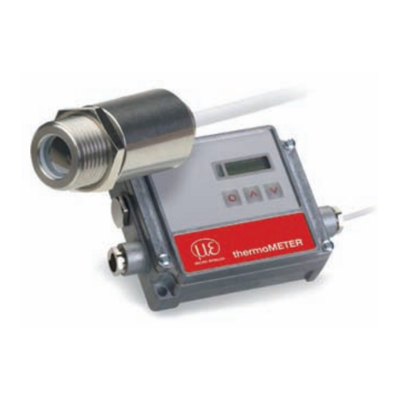
- Page 1 Instruction Manual thermoMETER CTM-1 CTM-2 CTM-3...
- Page 2 Infrared sensor MICRO-EPSILON MESSTECHNIK GmbH & Co. KG Königbacher Strasse 15 94496 Ortenburg / Germany Tel. +49 (0) 8542 / 168-0 Fax +49 (0) 8542 / 168-90 info@micro-epsilon.de www.micro-epsilon.com Certified acc. to DIN EN ISO 9001: 2008...
-
Page 3: Table Of Contents
Optical Charts ......................... 20 CF Lens and Protective Window ................... 28 Mechanical Installation ......................31 Mounting Accessories ........................... 33 Air Purge Collars ............................34 6.2.1 Standard Air Purge Collar ......................34 6.2.2 Laminar Air Purge Collar ......................35 thermoMETER CT... - Page 4 8.2.1.1 Installation ........................51 8.2.1.2 Driver Installation of Interface..................51 8.2.2 RS232 Interface ..........................52 8.2.2.1 Installation ........................52 8.2.2.2 Software Installation ....................52 8.2.3 RS485 Interface ..........................53 8.2.3.1 Installation ........................53 8.2.3.2 Sensor Installation ....................... 54 thermoMETER CT...
- Page 5 CompactConnect Software ....................82 11.1 System Requirements ........................... 82 11.2 Main Features ..............................82 Communication Settings ......................83 12.1 Serial Interface ............................... 83 12.2 Protocol ................................83 12.3 ASCII Protocol .............................. 83 12.4 Saving of Parameter Settings ........................84 thermoMETER CT...
- Page 6 Determination of Unknown Emissivity ......................86 14.3 Characteristic Emissivity ..........................87 Warranty ..........................88 Service, Repair ........................89 Decommissioning, Disposal ....................89 Appendix Factory Settings ........................90 Emissivity Table Metals ......................92 Emissivity Table Non Metals ....................95 Smart Averaging ........................97 thermoMETER CT...
-
Page 7: Safety
> Damage to or destruction of the sensor and/or controller The power supply must not exceed the specified limits. > Damage to or destruction of the sensor and/or controller Protect the sensor cable against damage. > Destruction of the sensor, Failure of the measuring device thermoMETER CT Page 7... -
Page 8: Notes On Ce Identification
No solvent-based cleaning agents may have an effect on the sensor (neither for the optics nor the housing) > Damage to or destruction of the sensor Notes on CE Identification The following applies to the thermoMETER CT: - EU directive 2004/108/EC - EU directive 2011/65/EU, “RoHS“ category 9 Products which carry the CE mark satisfy the requirements of the quoted EU directives and the European standards (EN) listed therein. -
Page 9: Proper Use
Safety Proper Use - The thermoMETER CT is designed for use in industrial and laboratory areas. It is used for non-contact temperature measurement. - The system may only be operated within the limits specified in the technical data, see Chap. 2.. -
Page 10: Technical Data
Chap. The sensor housing of the thermoMETER CT is made from stainless steel (protection class IP 65/ NEMA 4), the controller is placed in a separate box made of die casting zinc. -
Page 11: Sensor Models
Temperature of thin film plastics In the following chapters of this manual you will find only the short model codes. On the CTM-1, CTM-2 and CTM-3 models the whole measuring range is split into several sub ranges. thermoMETER CT Page 11... -
Page 12: General Specifications
IEC 68-2-6: 3 g 11 - 200 Hz, any axis Shock IEC 68-2-27: 50 g, 11 ms, any axis CompactConnect optional Software Electromagnetic EN 61326-1: 2006 and EN 61326-2-3: 2006 compatibility (EMC) 1) The CTM-3 models are only available with 3 m cable. thermoMETER CT Page 12... -
Page 13: Electrical Specifications
(optional plug-in modules) Functional inputs F1 up to F3; software programmable for the following functions: - external emissivity adjustment - ambient temperature compensation, - trigger (reset of hold functions) Input impedance F2 and F3: 43 kΩ thermoMETER CT Page 13... -
Page 14: Measurement Specifications
4) At time constant 200 ms and an object temperature of 25 °C 5) For ambient temperatures (sensor): 18 °C ≤ sensor ≤ 28 °C On the CT models CT-SF02 the sensor cable must not be moved during the measurement. thermoMETER CT Page 14... -
Page 15: Ctf / Cth Models
4) At time constant 100 ms with smart averaging and an object temperature of 25 °C 5) For ambient temperatures (sensor): 18 °C ≤ sensor ≤ 28 °C On the CTH models CTH-SF02/ CTH-SF10 the sensor cable must not be moved during the measure- ment. thermoMETER CT Page 15... -
Page 16: Ctm / Ctp Models
2) Accuracy for thermocouple output: ±2,5 °C or ±1 % 3) e = 1 / Response time 1 s 4) With dynamic adaptation at low signal levels 5) For ambient temperatures (sensor): 18 °C ≤ sensor ≤ 28 °C thermoMETER CT Page 16... - Page 17 3) Accuracy for thermocouple output: ±2.5°C or ±1 % 4) e = 1/ Response time 1 s 5) With dynamic adaptation at low signal levels 5) For ambient temperatures (sensor): 18 °C ≤ sensor ≤ 28 °C thermoMETER CT Page 17...
- Page 18 2) Accuracy for thermocouple output: ±2.5 °C or ±1 % 3) e = 1 / Response time 1 s 4) With dynamic adaptation at low signal levels 5) For ambient temperatures (sensor): 18 °C ≤ sensor ≤ 28 °C thermoMETER CT Page 18...
-
Page 19: Delivery
Delivery Delivery Unpacking 1 thermoMETER CT sensor 1 Controller 1 Connection cable 1 Mounting nut 1 Instruction manual Check the delivery for completeness and shipping damage immediately after unpacking. In case of damage or missing parts, please contact the manufacturer or supplier. -
Page 20: Optical Charts
D = Distance from the front of the sensor to the object S = Spot size The D:S ratio is valid for the focus point. CTF-SF25 Optics: SF D:S: 25:1 CT-SF22 Optics: SF D:S: 22:1 thermoMETER CT Page 20... - Page 21 Optical Charts CT-CF22 Optics: CF integrated D:S: 22:1 2.3mm@ 50mm D:S (far field) = 6:1 CT-SF15 CTF-SF15 Optics: SF D:S: 15:1 CT-CF15 Optics: CF integrated D:S: 15:1 3.0mm@ 50mm D:S (far field) = 5:1 thermoMETER CT Page 21...
- Page 22 Optical Charts CTH-SF10 Optics: SF D:S: 10:1 CTH-CF10 Optics: CF1 integrated D:S: 10:1 3.0mm@ 30mm D:S (far field) = 3:1 thermoMETER CT Page 22...
- Page 23 Optical Charts CT-SF02 CTH-SF02 Optics: SF D:S: CTM-1CF40 CTM-2CF40 Optics: CF integrated D:S: 40:1 2.7mm@ 110mm D:S (far field) = 12:1 thermoMETER CT Page 23...
- Page 24 Optical Charts CTM-1SF40 CTM-2SF40 Optics: SF D:S: 40:1 CTM-1CF75 CTM-1CF75H1 CTM-2CF75 CTM-2CF75H1 CTM-3CF75H1 CTM-3CF75H2 CTM-3CF75H3 Optics: CF integrated D:S: 75:1 1.5mm@ 110mm D:S (far field) = 14:1 thermoMETER CT Page 24...
- Page 25 Optical Charts CTM-1SF75 CTM-1SF75H1 CTM-2SF75 CTM-2SF75H1 CTM-3SF75H1 CTM-3SF75H2 CTM-3SF75H3 Optics: SF D:S: 75:1 CTM-3SF22 Optics: SF D:S: 22:1 CTM-3CF1-22 Optics: CF1 integrated D:S: 22:1 1.5mm@ 30mm D:S (far field) = 3.5:1 thermoMETER CT Page 25...
- Page 26 Optical Charts CTM-3SF22 Optics: CF D:S: 22:1 5mm@ 110mm D:S (far field) = 9:1 CTM-3SF33 Optics: SF D:S: 33:1 CTM-3CF1-33 Optics: CF1 D:S: 33:1 1.0mm@ 30mm D:S (far field) = 4:1 thermoMETER CT Page 26...
- Page 27 Optical Charts CTM-3CF33 Optics: CF D:S: 33:1 3.4mm@ 110mm D:S (far field) = 11:1 thermoMETER CT Page 27...
-
Page 28: Cf Lens And Protective Window
Protective window with external thread for installation in massive housing [CTM-1/ CTM-2/CTM-3] If the protective window is used, the transmission has to be set as follows (average values): 0.83 [CT- SF02/CT-SF15/CT-SF22] or 0.93 [CTM-1, CTM-2, CTM-3]. thermoMETER CT Page 28... - Page 29 0.5 mm @ 8 mm 0.5 mm @ 6 mm [TM-APLCF-CT] D:S (far field) = 1.6:1 CT-SF22 + CF lens 0.6 mm @ 10 mm 0.6 mm @ 8 mm [TM-APLCF-CT] D:S (far field CF) = 1.5:1 thermoMETER CT Page 29...
- Page 30 1.2 mm @ 10 mm 1.2 mm @ 8 mm [TM-APLCF-CT] D:S (far field) = 1.2:1 CT-SF02 / CTH-SF02 + CF lens 2.5 mm @ 23 mm 2.5 mm @ 21 mm [TM-APLCF-CT] D:S (far field) = 5:1 thermoMETER CT Page 30...
-
Page 31: Mechanical Installation
Mechanical Installation Mechanical Installation The thermoMETER CT sensors are equipped with a metrical M12x1-thread and can be installed either directly via the sensor thread or by means of the hex nut (included in scope of supply) to the mounting bracket available. - Page 32 [TM-COV-CT] The controller is also available with closed cover (no access to display and programming keys from outside) [TM-COV-CT]. On the CT-SF02, CTH-SF02 and CTH-SF10 models the sensor cable must not be moved during the measurement. thermoMETER CT Page 32...
-
Page 33: Mounting Accessories
The mounting bracket, adjustable in two axes axes, can be combined with the mounting bracket [TM-AB-CT] consisting of TM-FB-CT and TM-MB-CT. [TM-FB-CT] using the M12x1 thread. Fig. 11 Mounting fork [TM-MG-CT] Fig. 12 Mounting bracket [TM-AB-CT] thermoMETER CT Page 33... -
Page 34: Air Purge Collars
Thread (fitting): M5 Fig. 13 Standard air purge collar [TM-AP-CT] Fig. 14 Standard air purge collar [TM-AP2-CT] The needed amount of air (approximately 2 ... 10 l/min.) depends on the application and the installation con- ditions on-site. thermoMETER CT Page 34... -
Page 35: Laminar Air Purge Collar
Fig. 15 Laminar air purge collar [TM-AP-CT] Fig. 16 Laminar air purge collar and mounting fork [TM-APL-CT + TM-MG-CT] The needed amount of air (approximately 2 ... 10 l/min.) depends on the application and the installation con- ditions on-site. thermoMETER CT Page 35... -
Page 36: Further Accessories
If the mirror is used this value has to be multiplied by the emissivity value of the measurement object. Example: CT-SF22 and object with emissivity = 0.85 0.85 x 0.96 = 0.816 Thus the emissivity in the CT-SF22 has to be set to the resulting value of 0.816. thermoMETER CT Page 36... -
Page 37: Rail Mount Adapter For Controller
Fig. 18 Rail mount adapter for controller [TM-RAIL-CT] 6.3.3 Tilt Assembly for CT Sensors With this mounting accessory a fine adjustment of the CT sensor with an off-axis angle ±6,5 ° is possible. Fig. 19 Tilt assembly [TM-TAS-CT] thermoMETER CT Page 37... -
Page 38: Laser Sighting Tool
Fig. 21 Laser label beam. Avoid indirect During operation the pertinent regulations acc. to DIN EN 60825-1: 2007 on “radiation safety of laser equip- exposure via reflective surfaces! ment” must be fully observed at all times. thermoMETER CT Page 38... -
Page 39: Oem Laser Sighting Tool
CompactConnect software. The special double-hole mounting bracket [TM-FB2-CT] allows a simultaneous mounting of the CT sensor and the laser head. Fig. 22 OEM laser sighting tool [TM-LSTOEM-CT] Fig. 23 Double-hole mounting bracket [TM-FB2-CT] thermoMETER CT Page 39... -
Page 40: Massive Housing
[TM-PWAG-CT], see Chap. For an optimum function of the massive housing 10 cm of the sensor cable must be installed in loops inside the housing. CT sensor Massive housing Sensor cable Fig. 26 Massive housing thermoMETER CT Page 40... -
Page 41: Accessories For Massive Housing
Mechanical Installation 6.3.7 Accessories for Massive Housing Fig. 27 Air purge collar for massive housing Fig. 28 Mounting bracket for massive housing, (thread M18x1) [TM-APMH-CT] adjustable in one axis [TM-FBMH-CT] thermoMETER CT Page 41... -
Page 42: Pipe Adapter And Sighting Tubes
Length: 20 mm TM-ST40-CT Length: 40 mm TM-ST88-CT Length: 88 mm Fig. 29 Pipe adapter TM-PA-CT Fig. 30 Sighting tube TM-ST40-CT The sighting tubes can only be used for sensors with a distance-to-spot ratio (D:S) of ≥ 15:1. thermoMETER CT Page 42... -
Page 43: Electrical Installation
Electrical Installation Electrical Installation Cable Connections For the electrical installation of the thermoMETER CT, please open at first the cover of the controller (4 screws). Below the display are screw terminals for the cable connection. 7.1.1 Pin Assignment 7.1.1.1 CT-SF02, CT-SF15, CT-SF22, CTF-SF15, CTF-SF25, CTH-SF02, CTH-SF10, CTP Models Designation +8 ... -
Page 44: Ctm-1, Ctm-2, Ctm-3 Models
Please use a power supply unit with an output voltage of 8 – 36 VDC/100 mA. The ripple should be max. 200 mV. Please do never connect a supply voltage to the analog outputs. > Destruction of the output The thermoMETER CT is not a 2-wire sensor! thermoMETER CT Page 44... -
Page 45: Cable Assembling
Every single wire may be connected to the appropriate screw clamps according to their colors. Metal washer Rubber washer Pressing screw Shield Fig. 33 Cable assembling Use shielded cables only! The sensor shield has to be grounded! thermoMETER CT Page 45... -
Page 46: Ground Connection
To do so, please put the jumper in the other position [middle and right pin connected]. If the thermocouple output is used, the connection GND housing should generally be interrupted. Fig. 34 Connector (jumper) thermoMETER CT Page 46... -
Page 47: Exchange Of The Sensor
3 blocks (CTM-1, CTM-2, CTM-3 = 5 blocks) with 4 characters each. Example: A6FG - 22KB - 0AS0 block 1 block 2 block 3 After exchanging a sensor the calibration code of the new sensor must be entered into the controller. Fig. 35 Calibration code thermoMETER CT Page 47... -
Page 48: Sensor Cable
A shortening of the cable will cause an additional measuring error of about 0.1 K/ m. The CTM-3 models are only available with 3 m cable. On the CT models CT-SF02 / CTH-SF02 / CTH-SF10 the sensor cable must not be moved during the measurement. thermoMETER CT Page 48... -
Page 49: Outputs And Inputs
Outputs and Inputs Outputs and Inputs Analog Outputs The thermoMETER CT has two analog output channels. Please do never connect a supply voltage to the analog outputs. The thermoMETER CT is not a 2-wire sen- sor! > Destruction of output 8.1.1 Output Channel 1 This output is used for the object temperature. -
Page 50: Digital Interfaces
Exchange the blind screw on the controller by the cable gland of the respective interface and install the appropriate interface cable. Please also pay attention to the additional notes for installing the respective interfaces, see Chap. 8.2.1, see Chap. 8.2.2 and the following interface chapters. thermoMETER CT Page 50... -
Page 51: Usb Interface
After you have connected the USB-cable to your PC and started the CompactConnect software the com- munication will be established. If the recognition is not automatic, you will find the drivers on the Compact Connect Software CD in the path \Driver \ Infrared Sensor Adapter. thermoMETER CT Page 51... -
Page 52: Rs232 Interface
After you have connected the RS232 cable to your PC and started the CompactConnect software the com- munication will be established. The setting for baud rate in the CompactConnect software must be the same as on the thermoMETER CT unit (factory default: 9.6 kBaud). -
Page 53: Rs485 Interface
Make sure that you always connect A to A and B to B, not reverse. You may run up to 32 CT units on one RS485-USB adapter. Turn the 120R-switch to ON only at one of the connected CT units. Fig. 38 Pin assignment RS485 thermoMETER CT Page 53... -
Page 54: Sensor Installation
After it has been connected the computer will recognize a new USB device and (if connected the first time) will ask for installation of the according driver software. Please select Search and install the RS485 adapter USB driver from the CompactConnect software CD. thermoMETER CT Page 54... - Page 55 Make sure the wiring is correct, see Fig. We recommend for industrial installations to connect the shield of the Profibus cable with the controller housing (inside the cable gland). The thermoMETER CT always needs an external power supply. Connector Color Function...
- Page 56 The measuring values are displayed in hex format and must be converted into decimals; see the Profibus instruction manual on page 7 on CompactConnect Software CD. The settings of the DPv1 Profibus interface and the communication with the Profibus master are described in the Profibus instruction manual on CompactConnect Software CD. thermoMETER CT Page 56...
- Page 57 We recommend for industrial installations to connect the shield of the CAN BUS cable with the control- ler housing (inside the cable gland). The thermoMETER CT always needs an external power supply. CAN Protocol CAN open (see documentation on CompactConnect software CD)
- Page 58 B4: DA B5: 07 T = 20.10 °C Before delivery, MICRO-EPSILON can set parameters, desired by the customer, for an extra charge. For the subsequent conversion a CAN master is required. Diagnosis If the power supply is on, the LED displays one of the following conditions:...
- Page 59 In case you want to run the pre-mounted cable of the Ethernet box through the delivered cable gland, the terminal block has to be disassembled/assembled. The thermoMETER CT always requires an external power supply of at least 12 V. Make sure the wiring is correct according to the colors printed on the interface board.
- Page 60 If the autorun option is activated the installation wizard will start automatically. Otherwise please start CDset- up.exe from the CompactConnect software CD. The following screen will appear, see Fig. Fig. 41 View CompactConnect CD-ROM Now install the device driver by selecting Install Ethernet Driver. thermoMETER CT Page 60...
- Page 61 The IP and MAC address of the Ethernet adapter will appear in the list. You will find the MAC address also printed on the Ethernet adapter. Please mark the adapter in the list and press Weiter. thermoMETER CT Page 61...
- Page 62 Outputs and Inputs The following screen shows all settings. The device will be installed inside the network. Please press Fertig stellen. thermoMETER CT Page 62...
- Page 63 To deinstall an adapter please follow the steps de- net adapter are shown. scribed under Network Installation, see Chap. 8.2.6.2. Select the adapter(s) which should be dein- Select Remove an Existing Device and stalled and press Weiter. press then Weiter. thermoMETER CT Page 63...
- Page 64 Please open the tab Advanced in this win- adapter (serial) from the list. dow. Beside Device UI you will find a link with the network IP address. By double clicking the desired Ethernet adapter, a properties window is opening. thermoMETER CT Page 64...
- Page 65 Outputs and Inputs By clicking on the link the configuration page for the Ethernet adapter will be opened in your web browser. Please select Network (Navigation left; below configuration). thermoMETER CT Page 65...
- Page 66 Outputs and Inputs In the input mask Use the following IP address below you can now enter a fixed IP address. Confirm your settings with Apply. thermoMETER CT Page 66...
- Page 67 For a communication with the adapter you now have to configure the network settings on your PC. Please open the LAN settings (Start/Control panel/Network settings/Settings). Mark the LAN connection and open the properties window using the right mouse button. thermoMETER CT Page 67...
- Page 68 Please enter here a fixed IP address for the ternet protocol (TCP/IP). Please note that the first three blocks (ex- ample: 192.168.049) have to match with the IP address of the adapter device. Press OK. The installation is finished. thermoMETER CT Page 68...
- Page 69 USB devices in the menu point Preferences/ Options: 1) Polling Mode = Method, to determine the status of a device consisting of hardware or software or the event of a change of values by cyclic queries. thermoMETER CT Page 69...
- Page 70 The adapter works in the DHCP mode after resetting. If you want to make a direct connection to a PC, see Chap. 8.2.6.4. 1) Flashing - break - 5 x flashing - break - flashing 2) If necessary only some values are reset. thermoMETER CT Page 70...
- Page 71 Outputs and Inputs Relays Outputs The thermoMETER CT can optionally be equipped with a relay output. The relay board is installed the same way as the digital interfaces, see Chap. 8.2. Connect the external electrical circuit with the terminal blocks.
- Page 72 -40 - 900 °C/preset range: -20 - 200 °C] F1 - F3 (digital) Emissivity (digital choice via table) A non-connected input represents: F1 = High F2, F3 = Low High-level: +3 V ... +36 V ≥ Low-level: ≤ +0.4 V ... -36 V thermoMETER CT Page 72...
- Page 73 Outputs and Inputs Alarms The thermoMETER CT has following alarm features: All alarms (alarm 1, alarm 2, output channel 1 and 2 if used as alarm output) have a fixed hysteresis of 2 K CTH: 1 K). 8.5.1 Output Channel 1 and 2 (Channel 2 on CT-SF / CTP) The respective output channel has to be switched into digital mode for activation.
- Page 74 INIT. After this procedure the object temperature is shown in the display. The display backlight color changes according to the alarm settings, see Chap. 8.5, see Chap. 8.5.2. Restoring Factory Setting To set the thermoMETER CT back to the factory settings, please first press the and then the but- ton and keep both pressed for approximately 3 seconds.
- Page 75 B 9.6 Baud rate in kBaud [9.6] 9.6/19.2/38.4/57.6/115.2 kBaud S ON Laser eyepiece (3 VDC-switches to the con- ON/OFF; This menu item appears on the models nection pin „3 VSW“) CTM-1, CTM-2, CTM-3 on first position. thermoMETER CT Page 75...
- Page 76 Mode Down Fig. 43 Display and programming keys Pressing the button again recalls the last called function on the display. The signal processing features peak hold and valley hold cannot be selected simultaneously. thermoMETER CT Page 76...
- Page 77 Setup of valley hold. In this mode the sensor waits for ascending signals. The definition of the algorithm is equal to the peak hold algorithm (inverted). If the value is set to 0.0 the display will show --- (function deactivated). thermoMETER CT Page 77...
- Page 78 Setup of the lower limit of the signal output. This setting allows an assignment of a certain sig- nal output level to the lower limit of the temperature range. The adjustment range corresponds to the selected output mode (e.g. 0 - 5 V). thermoMETER CT Page 78...
- Page 79 Setup of the baud rate for digital data transfer S ON Activating (ON) and Deactivating (OFF) of an optional sighting laser, see Chap. 6.3. By pressing a voltage of 3 VDC will be switched to the 3V SW connection pin on the controller. thermoMETER CT Page 79...
- Page 80 Operating Error Messages The display of the thermoMETER CT can show the following error messages: 9.4.1 CT-SF02, CT-SF15, CT-SF22, CTH and CTP Models OVER Object temperature too high UNDER Object temperature too low ^^^CH Sensor temperature to high vvvCH Sensor temperature to low 9.4.2...
- Page 81 Lens cleaning: Blow off loose particles using clean compressed air. The lens surface can be cleaned with a soft, humid tissue moistened with water or a water based glass cleaner. Never use cleaning compounds which contain solvents (neither for the lens nor for the housing). > Destruction of the sensor and/or the controller thermoMETER CT Page 81...
- Page 82 - Graphical display for temperature measuring values and automatic data logging for analysis and documentation - Complete sensor setup and remote controlling - Adjustment of signal processing functions - Programming of outputs and functional inputs Fig. 45 Graphic display main features thermoMETER CT Page 82...
- Page 83 After you have modified the sensor calibration code a reset is necessary to activate the change, see Chap. To switch to the ASCII protocol you can also use the following command: Decimal: HEX: 0x83 Data, answer: byte 1 Result: 0 – Binary protocol 1 – ASCII protocol thermoMETER CT Page 83...
- Page 84 The command 0x71 will poll the current status. You will find a detailed protocol and command description on the CompactConnect software CD in the direc- tory: \Commands. thermoMETER CT Page 84...
- Page 85 Distance to Spot size. The spectral filter selects the wavelength range, which is relevant for the temperature measurement. The emitted infrared radiation is transformed into electrical signals by the detector and the controller. thermoMETER CT Page 85...
- Page 86 Afterwards, determine the temperature of a directly adjacent area and modify the emissivity until the measured value corresponds to the temperature of the colored surface. On all three methods the object temperature must be different from the ambient temperature. thermoMETER CT Page 86...
- Page 87 - Measuring angle - Geometry of the surface (smooth, convex, concave) - Thickness of the material - Constitution of the surface (polished, oxidized, rough, sandblast) - Spectral range of the measurement - Transmissivity (e.g. with thin films) thermoMETER CT Page 87...
- Page 88 The warranty period lasts 12 months following the day of shipment. Defective parts, except wear parts, will be repaired or replaced free of charge within this period if you return the device free of cost to MICRO-EPSILON. This warranty does not apply to damage resulting from abuse of the equipment and devices, from forceful handling or installation of the devices or from repair or modifications performed by third parties.
- Page 89 For customers in Canada or South America applies: Please contact your local distributor. Decommissioning, Disposal Disconnect the sensor and controller cables. The thermoMETER CT is produced according to the directive 2011/65/EU “RoHS“, Do the disposal according to the legal regulations (see directive 2002/96/EC). thermoMETER CT Seite 89...
- Page 90 CTM-1SF40 CTM-1SF75 CTM- CTM-2SF40 CTM-2SF75 CTF/CTH 1SF75H1 Lower limit temperature range [°C] Upper limit temperature range [°C] 1050 1800 2200 1600 Lower alarm limit [°C] 1200 (normally closed) Upper alarm limit [°C] 1400 1600 1200 (normally open) thermoMETER CT Seite 90...
- Page 91 Upper limit temperature range [°C] 1500 1800 Lower alarm limit [°C] (normally closed) Upper alarm limit [°C] 1000 1200 (normally open) Smart Averaging means a dynamic average adaptation at high signal edges (activation via CompactConnect software only), see Chap. thermoMETER CT Seite 91...
- Page 92 0.3 - 0.8 Inconel Electro 0.2 - 0.5 0.25 0.15 0.15 polished Sandblast 0.3 - 0.4 0.3 - 0.6 0.3 - 0.6 0.3 - 0.6 Oxidized 0.4 - 0.9 0.6 - 0.9 0.6 - 0.9 0.7 - 0.95 thermoMETER CT Seite 92...
- Page 93 0.1 - 0.14 Nickel Electrolytic 0.2 - 0.4 0.1 - 0.3 0.1 - 0.15 0.05 - 0.15 Oxidized 0.8 - 0.9 0.4 - 0.7 0.3 - 0.6 0.2 - 0.5 Platinum Black 0.95 Silver 0.04 0.02 0.02 0.02 thermoMETER CT Seite 93...
- Page 94 0.1 - 0.3 0.05 - 0.2 Oxidized 0.6 - 0.8 0.5 - 0.7 0.5 - 0.6 Wolfram Polished 0.35 - 0.4 0.1 - 0.3 0.05 - 0.25 0.03 - 0.1 Zinc Polished 0.05 0.03 0.02 Oxidized 0.15 thermoMETER CT Seite 94...
- Page 95 Gypsum 0.4 - 0.97 0.8 - 0.95 0.98 Limestone 0.4 - 0.98 0.98 Paint Non alcaline 0.9 - 0.95 Paper Any color 0.95 0.95 Plastic > 50 μm Non transparent 0.95 0.95 Rubber 0.95 Sand 0.95 thermoMETER CT Seite 95...
- Page 96 Appendix | Smart Averaging Material Typical Emissivity Spectral response 1.0 μm 2.2 μm 5.1 μm 8 - 14 μm Snow Soil 0.9 - 0.98 Textiles 0.95 0.95 Water 0.93 Wood Natural 0.9 - 0.95 0.9 - 0.95 thermoMETER CT Seite 96...
- Page 97 The function Smart Averaging eliminates this disadvantage by passing those fast events without averaging directly through to the signal output. Fig. 46 Signal curve with Smart Averaging function Fig. 47 Signal curve without Smart Averaging function thermoMETER CT Seite 97...
- Page 98 MICRO-EPSILON MESSTECHNIK GmbH & Co. KG X9751190-B041104HDR Königbacher Str. 15 · 94496 Ortenburg / Germany MICRO-EPSILON MESSTECHNIK Tel. +49 (0) 8542 / 168-0 · Fax +49 (0) 8542 / 168-90 *X9751190-B04* info@micro-epsilon.de · www.micro-epsilon.com...
Need help?
Do you have a question about the thermoMETER CT and is the answer not in the manual?
Questions and answers