Table of Contents
Advertisement
Advertisement
Table of Contents

Related Manuals for Keysight Technologies 11713B


Summary of Contents for Keysight Technologies 11713B
- Page 1 Keysight 11713B/C Attenuator/Switch Driver Operating and Service Manual...
- Page 2 FAR 27.401 or DFAR 227.7103-5 (c), adhered to, could result in personal injury or as applicable in any technical data. death. Do not proceed beyond a WARNING notice until the indicated conditions are fully understood and met. Keysight 11713B/C Operating and Service Manual...
-
Page 3: Certification
Certification Keysight Technologies certifies that this product met its published specifications at the time of shipment from the factory. Keysight Technologies further certifies that its calibration measurements are traceable to the United States National Institute of Standards and Technology (NIST, formerly NBS), to the extend allowed by the Institute’s calibration facility, and to the calibration facilities of the other International Standards Organization members. -
Page 4: Safety Considerations
Because of the danger of introducing additional hazards, do not install substitute parts or perform any unauthorized modification to the instrument. Return the instrument to a Keysight Technologies Sales and Service Office for service and repair to ensure that safety features are maintained. -
Page 5: Safety Symbols
WARNING If the device is used in a manner not specified by manufacturer, the device protection may be impaired. Keysight 11713B/C attenuator/switch drivers are designed for indoor use and in an area WARNING with low condensation. CLEAN WITH SLIGHTLY DAMPENED CLOTH CAUTION Clean the outside of the instrument with a soft, lint-free, slightly dampened cloth. -
Page 6: Regulatory Markings
This EMC statement applies to the equipment only for use in business environment. Safety and EMC Requirements This instrument is designed to comply with the following safety and EMC (Electromagnetic Compatibility) requirements: – Low Voltage Directive 2014/35/EU – EMC Directive 2014/30/EU Keysight 11713B/C Operating and Service Manual... -
Page 7: Waste Electrical And Electronic Equipment (Weee) Directive
To contact Keysight for sales and technical support, refer to the support links on the following Keysight websites: – www.keysight.com/find/11713 (product-specific information and support, software and documentation updates) – www.keysight.com/find/assist (worldwide contact information for repair and service) Keysight 11713B/C Operating and Service Manual... - Page 8 THIS PAGE HAS BEEN INTENTIONALLY LEFT BLANK Keysight 11713B/C Operating and Service Manual...
-
Page 9: Table Of Contents
..........18 11713B Front and Rear Panels at a Glance . - Page 10 ....... . 72 Exploring the 11713B/C Web Interface over LAN .
- Page 11 ....79 Figure 7-2 11713B/C Browser Web Control Interface ..... 81 Keysight 11713B/C Operating and Service Manual...
- Page 12 THIS PAGE HAS BEEN INTENTIONALLY LEFT BLANK. Keysight 11713B/C Operating and Service Manual...
- Page 13 Connecting accessories for Keysight 11713B/11713C ... . 18 Table 2-1 Summary of switches and attenuators connections to 11713B/C . . . 30 Table 2-2 11713B/C front panel and back panel properties .
- Page 14 THIS PAGE HAS BEEN INTENTIONALLY LEFT BLANK. Keysight 11713B/C Operating and Service Manual...
-
Page 15: Introduction
11713B Front and Rear Panels at a Glance 11713C Front and Rear Panels at a Glance This chapter provides an overview of the Keysight 11713B/C attenuator/switch drivers which includes the instruments’ functions and capabilities, compatibility with Keysight switching components, and physical appearances. -
Page 16: Key Features Of Keysight 11713B/C Attenuator/Switch Drivers
The 11713B attenuator/switch driver is a GPIB compatible instrument that concurrently drives up to two four-section programmable step attenuators and two microwave coaxial switches, or up to 10 SPDT switches. The 11713B is fully backward compatible with 11713A in terms of functionality and fit. Connectivity using USB and LAN are optional. -
Page 17: Compatible Keysight Attenuators And Switches
Introduction Compatible Keysight Attenuators and Switches The 11713B/C attenuator/switch drivers are designed to drive the following Keysight attenuators and switches. If you are using attenuators and switches made by another supplier, check the switching characteristics against those specified in Chapter 3, "Specifications". -
Page 18: Connecting Accessories
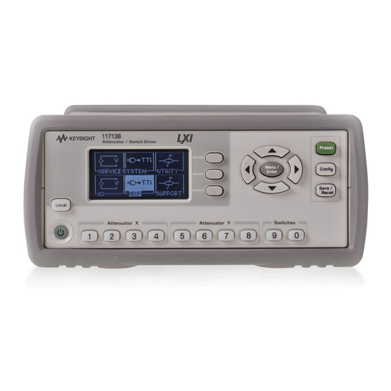
Refer to Keysight 11713A/B/C Attenuator/Switch Driver Configuration Guide, literature number 5989-3703EN, for configuration details. 11713B Front and Rear Panels at a Glance This section briefly describes the function of the front panel keys of 11713B. Keysight 11713B/C Operating and Service Manual... -
Page 19: Figure 1-1 11713B Front Panel Features
LED is red. Pressing the key once switches the driver on and the background LED turns to green. 12 Local. Press this key to control the driver from the front panel when it is operating via the remote interfaces. Keysight 11713B/C Operating and Service Manual... -
Page 20: Figure 1-2 11713B Rear Panel Features
Introduction This section briefly describes the function of the rear panel connectors of 11713B. Figure 1-2 11713B rear panel features 1 ATTEN X. Viking connector for connection to attenuator or switch(es). 2 ATTEN Y. Viking connector for connection to attenuator or switch(es). -
Page 21: 11713C Front And Rear Panels At A Glance
12 Attenuator Y for Bank 1. In the local mode, pushbuttons 5, 6, 7, and 8 change the attenuation setting of an attenuator or change the position of coaxial switch(es) connected to the ATTEN Y connector on the rear panel, for bank 1. Keysight 11713B/C Operating and Service Manual... - Page 22 LED is red. Pressing the key once switches the driver on and the background LED turns to green. 17 Local. Press this key to control the driver from the front panel when it is operating via the remote interfaces. Keysight 11713B/C Operating and Service Manual...
-
Page 23: Figure 1-4 11713C Rear Panel Features
15 GPIB connector. The interface connector from a source device to a listening device for the remote mode of operation. 16 LAN connector. The interface connector for LAN cable. 17 USB connector. The interface connector for Type mini B 5-pin USB cable. 18 Instrument markings. Keysight 11713B/C Operating and Service Manual... - Page 24 Introduction THIS PAGE HAS BEEN INTENTIONALLY LEFT BLANK. Keysight 11713B/C Operating and Service Manual...
- Page 25 Preparing for Use Connecting to Keysight Attenuators and Switches This chapter provides you important information on how to unpack and check your instrument, how to prepare your instrument for bench operation, and tips on configuring the 11713B/C with Keysight attenuators and switches.
-
Page 26: Installation
If the shipping container or cushioning material is damaged, the contents should be checked both mechanically and electrically. 2 If the contents are damaged or defective, contact your nearest Keysight Technologies Service and Support Office. Refer to “Sales and Technical Support”... -
Page 27: Preparing For Use
– (Top) Handle placed underneath the instrument to assure self- alignment of the instruments when stacked. – (Bottom) Handle tilted to raise the front of the instrument for easier viewing of the front panel. Figure 2-1 Handle positioning for bench operation Keysight 11713B/C Operating and Service Manual... -
Page 28: Figure 2-2 Illustrations Of Steps 2 And
4 °C for every 100 watts dissipated in the cabinet. If the total power dissipated in the cabinet is greater than 800 watts, forced convection must be used. Keysight 11713B/C Operating and Service Manual... -
Page 29: Figure 2-3 Illustration Of Completed Setup
4 °C for every 100 watts dissipated in the cabinet. If the total power dissipated in the cabinet is greater than 800 watts, forced convection must be used. Keysight 11713B/C Operating and Service Manual... -
Page 30: Connecting To Keysight Attenuators And Switches
Installation Connecting to Keysight Attenuators and Switches The 11713B/C attenuator/switch drivers can be used to drive various switches and attenuators. Table 2-1 shows the summary of switches and attenuators connections to the 11713B/C, with various interface cables for point-to-point connection. -
Page 31: Table 4-1 Table
Installation Table 2-1 Summary of switches and attenuators connections to 11713B/C (continued) Controlled by 11713B/C cable # of channels Controlled by Switches/attenuators ATTEN X (1-4) SWITCHES (9/0) option required ATTEN Y (5-8) Switches – 8768K Attenuators 001, 101 – 8494G/H –... -
Page 32: 11713B/C Front Panel And Back Panel Properties
Installation Table 2-2 11713B/C front panel and back panel properties Rear panel connectors Front panel pushbuttons Pushbutton Pushbutton number Pin numbers Wire color code LEDs Red (Vcc) White/Brown (Gnd) SWITCHES ATTEN X-3 (S9-A) Gray ATTEN X-4 (S9-B) White/Red ATTEN Y-3 (S0-A) -
Page 33: Figure 2-4 Typical Connection For A Programmable Four-Section Attenuator
– To use one four-section attenuator assembly, connect an attenuator interface cable either to the ATTEN X output (A6J1) or ATTEN Y output (A6J2). Connect all outputs (two for 11713B and four for 11713C) to have more than four attenuator segments. -
Page 34: Figure 2-5 Typical Connection For 8762 And 8765 Series Coaxial Switches
– Connections to Keysight 8761 series coaxial switches can only be made to S0 outputs and S9 outputs. – Figure 2-6 illustrates the rear panel connections to S9 outputs and the corresponding switch positions reflected by pushbutton indicators. Keysight 11713B/C Operating and Service Manual... -
Page 35: Figure 2-6 Typical Connection For 8761 Series Coaxial Switches
Installation Figure 2-6 Typical connection for 8761 series coaxial switches Keysight 11713B/C Operating and Service Manual... -
Page 36: Figure 2-7 Typical Connection For Relay Driving Circuit
Installation Driving relays – To drive ten devices for 11713B, connect attenuator cables at ATTEN X and Y and switch cables to S9 and S0. – A total of 10 relays may be on at one time if the total current is less than 1.7 A. However, since there are dual transistor and relay drivers, where one driver is on while the other is off, a total of 20 relays may be controlled. - Page 37 Keysight 11713B/C Attenuator/Switch Drivers Operating and Service Manual Specifications General Specifications Environmental Specifications This chapter provides you the specifications of Keysight 11713B/C attenuator/switch drivers.
-
Page 38: Specifications
GPIB interface operates to IEEE 488.2 and IEC 65 Interface 10/100 BaseT LAN interface USB 2.0 interface Command language SCPI standard interface commands (Keysight 11713A backward compatible) GPIB compatibility SH0, AH1, T0, TE0, L2, LE0, SR0, RL1, PP0, DC0, DT0, C0 Keysight 11713B/C Operating and Service Manual... -
Page 39: Environmental Specifications
Specifications Environmental Specifications Keysight 11713B/C attenuator/switch drivers are designed to fully comply with Keysight Technologies’ product operating environmental specifications as shown in the table below. Table 3-2 11713B/C environmental specifications Temperature – Operating 0 °C to +50 °C – Storage –40 °C to +70 °C... - Page 40 Specifications THIS PAGE HAS BEEN INTENTIONALLY LEFT BLANK. Keysight 11713B/C Operating and Service Manual...
-
Page 41: Verification
Keysight 11713B/C Attenuator/Switch Drivers Operating and Service Manual Verification Operator’s Check for Local Operation Operator’s Check for Remote Operation This chapter provides you simple instructions to verify Keysight 11713B/C attenuator/switch drivers’ functionality in both local operation and remote (GPIB/USB/LAN) operation. -
Page 42: Operator's Check For Local Operation
3 In addition, if any switching devices is connected (attenuators, relays, or switches), an audible click should be heard from the unit actuated. Pressing any numbered pushbutton should not cause any other pushbutton to change state. Keysight 11713B/C Operating and Service Manual... -
Page 43: Operator's Check For Remote Operation
These procedure verify that the driver can be controlled remotely using GPIB, USB, and/or LAN. 1 Refer to Chapter 7, "Remote Interface Configurations", to connect the 11713B/C to your computer through GPIB, USB, and/or LAN. 2 Once remote connection is available, send the following SCPI commands to the driver and note the changes on front panel LEDs. - Page 44 Verification THIS PAGE HAS BEEN INTENTIONALLY LEFT BLANK. Keysight 11713B/C Operating and Service Manual...
- Page 45 Getting Started with the 11713B/C Main Menu of the 11713B/C Save/Recall State Menu This chapter outlines some simple steps to start using the 11713B/C in local operations. Also, functionality of all menus are described to assist operations using the 11713B/C.
-
Page 46: Local Operations
NOTE 1 Connect the AC power supply to the 11713B/C. You should see: – the background LED of the power button is red which indicates that the 11713B/C is in the standby mode. 2 Press the power button once to turn on the 11713B/C. You should see: –... - Page 47 Repeat steps b and c if needed. e Model assigned to ATTEN X and ATTEN Y is marked <X> (e.g. 8494G/H) and <Y> (e.g. 8496G/H) respectively. f To return to the previous screen, press BACK softkey. Keysight 11713B/C Operating and Service Manual...
- Page 48 To exit this screen, press BACK softkey. To drive switches Step 2 — To drive switches, only applicable to the 11713C as the 11713B is NOTE predefined with +24 Vdc supply and no TTL drive. Keysight 11713B/C Operating and Service Manual...
- Page 49 (only for 11713C) d At the next screen, press OK softkey to confirm decision or press Cancel softkey to cancel. e Selection is marked <*>. f To exit this screen, press BACK softkey. Keysight 11713B/C Operating and Service Manual...
- Page 50 (only for d At the next screen, press OK 11713C) softkey to confirm decision or press Cancel softkey to cancel. e Output voltage assigned is marked <*>. f To exit this screen, press BACK softkey. Keysight 11713B/C Operating and Service Manual...
-
Page 51: Connection Between The 11713B/C And Programmable Attenuators
[a] If TTL is required, include Option 401. Must order switch with Option 403 (current interrupt) as switch cannot withstand continuous current supplied by 11713B/C. 4 For more details, refer to the 11713B/C Configuration Guide, literature number 5989-7277EN. Keysight 11713B/C Operating and Service Manual... -
Page 52: Main Menu Of The 11713B/C
On display are attenuator models assigned to ATTEN X and ATTEN Y 11713B/C for each bank (e.g. 8494G/H, 8496G/H, N/A, N/A). d Press Menu/Enter button again to return to main menu. Keysight 11713B/C Operating and Service Manual... - Page 53 Attenuation value on display changes according to the input from the front panel pushbuttons or through the virtual web interface: – Pushbutton LED ON — attenuation card selected (attenuation applied) on corresponding attenuator section – Pushbutton LED OFF — thru path selected (attenuation lifted) on corresponding attenuator section Keysight 11713B/C Operating and Service Manual...
- Page 54 Clear cycle for c At the next screen, press OK selected channel(s) softkey to confirm decision or press Cancel softkey to cancel. d.Note that relay cycle for B1-1 is 0 and below screen indicates CLEARED. Keysight 11713B/C Operating and Service Manual...
- Page 55 0. a Press Save All. Save cycle for all b At the next screen, Cycles saved. channels appears and this confirms all channels’ cycles are saved. Keysight 11713B/C Operating and Service Manual...
- Page 56 Press Menu/Enter button when – Firmware INFO icon is highlighted. revision c Press Menu/Enter button again to – GPIB address return to main menu. – LAN IP – USB address – MAC address Keysight 11713B/C Operating and Service Manual...
- Page 57 Recommendation: To enable the auto power on, it is recommended to use “Save Cycles” (via LCD display or SCPI remote command) to save the cycle count before powering the unit off. Keysight 11713B/C Operating and Service Manual...
- Page 58 Cancel softkey to cancel. Preset menu The preset function is used to apply full attenuation or open all switching paths (all LEDs light ON). For more information: “List of default values” on page 60. Keysight 11713B/C Operating and Service Manual...
-
Page 59: Save/Recall State Menu
Scroll to the desired state to recall configuration (e.g. STATE 2) using the navigation keys. To recall state c Press Recall State softkey to reinstate configuration. d Press Menu/Enter button again to return to main menu. Keysight 11713B/C Operating and Service Manual... - Page 60 Blank: Backup operation not performed. Save/Recall Settings that permit Save/Recall of a setup state. In the table, states that can be saved/recalled are denoted in the following manner: *: Save/Recall can be performed. Blank: Save/Recall cannot be performed. Keysight 11713B/C Operating and Service Manual...
- Page 61 Keysight 11713B/C Attenuator/Switch Drivers Operating and Service Manual Remote Operations Configuring Remote Interface Programming Guide (SCPI) Programming Guide (Legacy) SCPI and Legacy Commands Compatibility This chapter provides the programming guide for the 11713B/C in SCPI commands and legacy commands.
-
Page 62: Remote Operations
Each device on the GPIB (IEEE-488) interface must have a unique address. You can set the 11713B/C’s address to any value between 0 and 30. The attenuator/switch driver is shipped with a default address set to 28. The GPIB address is stored in non-volatile memory and does not change when the driver is switched off or after a remote interface reset. - Page 63 Connectivity Guide. If you have installed other I/O software, refer to the documentation that accompanies the software. LAN configuration The 11713B/C has three LAN operating modes: – Dynamic mode (Dynamic Host Configuration Protocol or DHCP) – Auto IP mode (Local PC Control or isolated LAN) –...
-
Page 64: Figure 6-1 Example Of Control Using Keysight Io Libraries Suite
Keysight IO Libraries Suite (when the I/P address of the 11713C is 10.74.73.33). Please ensure the remote instrument name is selected. Figure 6-1 Example of control using Keysight IO Libraries Suite Keysight 11713B/C Operating and Service Manual... -
Page 65: Programming Guide (Scpi)
Channel list is from 101 to 110 for bank 1 and 201 to 210 for bank 2. The 11713B has only one bank. Therefore, by default, b = 1. NOTE You can specify a bank, a single channel, multiple channels, or a range of channels as described below. - Page 66 P15, P24, or USER. – CONFigure:BANK1? – CONFigure:BANK2? To query number of relay cycles The command below query the number of relay cycles for each channel. Value to be returned: number of cycles. – DIAGnostic:RELay:CYCles? <channel list> Keysight 11713B/C Operating and Service Manual...
- Page 67 The commands below query the supply voltage set for each bank. Value to be returned: OFF, P5, P15, P24, or USER. – CONFigure:BANK1? – CONFigure:BANK2? To set TTL ON/OFF The commands below set TTL ON/OFF for each bank. – CONFigure:BANK1:TTL {OFF|ON} – CONFigure:BANK2:TTL {OFF|ON} Keysight 11713B/C Operating and Service Manual...
- Page 68 The command below query the number of relay cycles for each channel. Value to be returned: number of cycles. – DIAGnostic:RELay:CYCles? <channel list> To clear relay cycles The commands below clear relay cycle for selected or all channels. – DIAGnostic:RELay:CLEAr <channel list> – DIAGnostic:RELay:CLEAr:ALL Keysight 11713B/C Operating and Service Manual...
-
Page 69: Programming Guide (Legacy)
If Ax (Ay) uses a digit, then that digit may not be used in Bx (By). NOTE – A/B 9 = legacy command for switch S9 – A/B 0 = legacy command for switch S0 Keysight 11713B/C Operating and Service Manual... -
Page 70: Scpi And Legacy Commands Compatibility
LED lights on = attenuation applied (for attenuators)/switching path opened (for switches). LED lights off = no attenuation (for attenuators)/switching path closed. Legends H = Open (Low) L = Closed (High) G = Connected to ground Keysight 11713B/C Operating and Service Manual... -
Page 71: Remote Interface Configurations
Exploring the 11713B/C Web Interface over LAN This chapter provides you information and steps to establish remote connections with the Keysight 11713B/C attenuator/switch drivers via GPIB, USB, and LAN. You will also be introduced to the 11713B/C web interface over LAN. -
Page 72: Connecting The 11713B/C To Your Computer
If you have installed any other I/O software, refer to the documentation NOTE included with that software. 7 The 11713B/C is shipped from the factory with a default GPIB address of 28. To change the address, refer to table below: Keysight 11713B/C Operating and Service Manual... - Page 73 72 for more information on installing the Keysight IO Libraries software. 1 After the I/O software is installed on your computer, connect a 11713B/C to your computer using a Type Mini-B 5 pin USB cable. 2 Make sure power is applied to your computer and verify that the operating system is fully booted.
- Page 74 NOTE documentation included in that software. 4 Use the Connectivity Expert utility of the Keysight I/O Libraries Suite to verify that the 11713B/ C is displayed under the USB interface. 5 Now you can use various programming environments to control the 11713B/C. For an overview on programming instructions via USB, refer to the Connectivity Guide.
- Page 75 Apply power to 11713B/C and background LED color turns red, indicating standby mode. connected to d Allow 11713B/C to warm up for 15 seconds, then press the ON button (LED turns from red to green). a Press Menu/Enter button on the front panel of 11713B/C.
- Page 76 I/O software on your computer. Use the Connectivity Expert utility of the Keysight IO Libraries Suite to add the 11713B/C and verify a connection. When identifying the instrument, it is easiest if you use the IP address noted in step 3 above.
- Page 77 Apply power to 11713B/C and background LED color turns red, indicating standby mode. 11713B/C are d Allow 11713B/C to warm up for 15 seconds, then press the ON button (LED turns from red to green). turned on a Press Menu/Enter button on the front panel of 11713B/C.
- Page 78 I/O software on your computer. Use the Connectivity Expert utility of the Keysight IO Libraries Suite to add the 11713B/C and verify a connection. When identifying the instrument, it is easiest if you use the IP address noted in step 3 above.
-
Page 79: Exploring The 11713B/C Web Interface Over Lan
4 Exit the Options window. 5 Enter the IP address of the 11713B/C in the Address field and press return. Use the 11713B/C’s front panel utility menu to read the IP address. 6 After entering the appropriate IP address, the 11713B/C Web Interface’s Welcome Window should appear. - Page 80 2 You will notice a pop-up window, requesting for password. 3 Enter password (default password is “keysight”) and click submit. 4 You can view the virtual front panel of the 11713B/C. 5 Now, you can control the switching devices remotely, similar to the front panel of the actual instrument.
-
Page 81: Figure 7-2 11713B/C Browser Web Control Interface
Remote Interface Configurations Figure 7-2 11713B/C Browser Web Control Interface Keysight 11713B/C Operating and Service Manual... - Page 82 Remote Interface Configurations THIS PAGE HAS BEEN INTENTIONALLY LEFT BLANK. Keysight 11713B/C Operating and Service Manual...
- Page 83 Keysight 11713B/C Attenuator/Switch Drivers Operating and Service Manual Servicing the Attenuator/Switch Driver Preparing a Static-Safe Workstation Maintenance and Adjustments This chapter provides the procedures for removal and replacement of major assemblies in the 11713B/C and the list of replaceable parts.
-
Page 84: Servicing The Attenuator/Switch Driver
Wrist-strap, color black, stainless steel, without cord, has four adjustable links, and a 7 mm 9300-1367 post-type connection 9300-1308 ESD heel-strap (reusable 6 to 12 months) The above can be ordered by contacting any Keysight Sales Office. Keysight 11713B/C Operating and Service Manual... - Page 85 – PC board assembly edge-connector contacts may be cleaned by using a lint-free cloth with a solution of 80% electronics-grade isopropyl alcohol and 20% deionized water. This should be performed at a static-safe workstation. Keysight 11713B/C Operating and Service Manual...
-
Page 86: Maintenance And Adjustments
Be sure to select the correct fuse rating for the selected line voltage. Do not NOTE use repaired fuses or short circuited fuse-holders. To do so could cause a shock or fire hazard. Adjustment The 11713B/C attenuator/switch driver has no internal electrical or mechanical adjustments. Keysight 11713B/C Operating and Service Manual... - Page 87 This information is subject to change without notice. Always refer to the Keysight website for the latest revision. © Keysight Technologies 2007-2020 Edition 4, December 4, 2020 Printed in Malaysia 11713-90024 www.keysight.com...
Need help?
Do you have a question about the 11713B and is the answer not in the manual?
Questions and answers