
Related Manuals for Flight Model Courage-8 40


Summary of Contents for Flight Model Courage-8 40
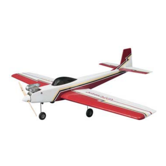
- Page 1 CONSTRUCTION GUIDE SPECIFICATION: Wing span:57in/1448mm Wing area:36.1sq.dm Length:44.3in/1125mm Flying weight:2100-2350g Engine:2cycle 40-46 Radio:4channels 4servos...
- Page 2 1 Epoxy the 2 identical plywood wing joiners together. Cut out aileron servo opening on top of wing panels. 2 Looking forward towards the leading edge, the wing should form a "V" when assembled. The top of the wing has lettering on it.
- Page 3 Next, glue the hardwood torque rod covers in place. They have a notch in them to allow for movement of the aileron rod. You may have to enlarge the holea little to allow for proper movement. The wing is joined together by inserting one plywood dihedral braces into each wing panel and then epoxying into place.You may want to check the fit first, before gluing.
- Page 4 The nose gear is incorporated into the engine mount. The steering cable is routed along the left side of the fuselage and attached to rudder servo.Check the diagram for assembly. Hook up noes wheel steering pushrod and route through housing which is installed into servo area. 6 Assembly the fuel tank as shown.
- Page 5 7 Offset the engine by two degrees to the right. Drill four 7/64" holes for the engine. Use the selftapping screws supplied. Install the nose wheel assembly at this time.
- Page 6 8 The elevator must be attached to horizontal stabilizer using 3 hinges. You may have to trim the elevator to fit the stabilizer. The stabilizer should be flush with rear of the fuselage as per the diagram. IT IS ESSENTIAL THAT THE STABILIZER AND THE RUDDER ARE 90 DEGREES TO EACH OTHER, AND THAT THE WING 15 PARALLEL TO THE STABILIZER.
- Page 7 Two wooden dowels are inserted through the fuselage to hold the wing in place. No.62 rubber bands are used to attach the wing.At least 4 rubber bands should be used on each side. At this time be certain that the aileton servo is connected to the receiver,otherwise the wing will need to be removed later to connect it.
- Page 8 Check the size of the servo holes in the fuselage servo tray; alter as necessary. epoxy into the fuse, and install the servos. Tutn on the system and check the operation of the servos; they shuold all work without interfering with each other or the fuse. The pushrods are made of wood and are to be assembled as shown in the drawing.
- Page 9 The canopy is installed as shown using epoxy glue. The amount of the travel needed for the variour control surfaces is shown.
Need help?
Do you have a question about the Courage-8 40 and is the answer not in the manual?
Questions and answers