Neptronic SKE4-E Series Installation Instructions And User Manual
Steam humidifier
Hide thumbs
Also See for SKE4-E Series:
- Installation instructions and user manual (60 pages) ,
- Manual (52 pages)

Related Manuals for Neptronic SKE4-E Series


Summary of Contents for Neptronic SKE4-E Series
- Page 1 S ea idifie SKE4-E Series Installation Instructions and User Manual READ AND SAVE THESE INSTRUCTIONS SKE4-E-ESA-191018...
- Page 2 Please observe the local regulations concerning the provision of electrical installations. Correct Use Neptronic systems and its products are designed only for humidification use. Any other application is not considered appropriate for the intended purpose. The manufacturer cannot be made liable for any damage resulting from incorrect use.
-
Page 3: Table Of Contents
Steam Dispersion System Selection ....................18 Positioning S.A.M. and S.A.M.E2 ....................20 Placement of Steam Pipe in Horizontal Duct ................. 21 Placement of Steam Pipe in Vertical Duct ..................22 Steam Output Connections ........................23 www.neptronic.com Page | - 2 -... - Page 4 Initial Verification ..........................60 Start-Up ............................. 61 Service ..............................62 Cleaning the Evaporation Chamber ....................62 Troubleshooting ............................ 67 Exploded View and Bill of Material ......................68 Exploded View ........................... 68 Bill of Material ............................ 70 www.neptronic.com Page | - 3 -...
-
Page 5: Overview
(less than 1500 mm). Steam manifold with two eyelets, adapted for applications with Steam Absorption Manifold restricted air duct dimensions. Allows steam absorption for with 2 Eyelets (S.A.M.E2) relatively short distance applications (less than 1500 mm). www.neptronic.com Page | - 4 -... -
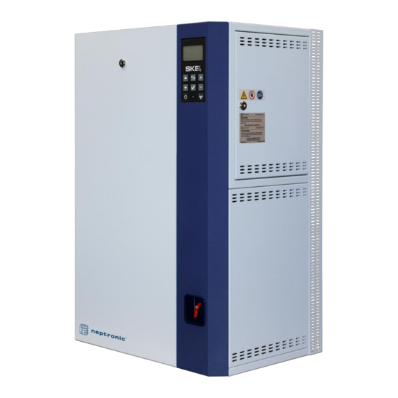
Page 6: Visual Overview
Manual Drain Valve Right Side Printed Circuit Board Access Door to Evaporation Low Voltage Chamber Compartment Rail Guide Access Panel to High Voltage Compartment Illustration 1 - Overview of the Humidifier (SKE4-E05 to E80) www.neptronic.com Page | - 5 -... - Page 7 SKE4-E Steam Humidifier Installation Instructions and User Manual Illustration 2 - Overview of the Humidifier (SKE4-E90 to E120) www.neptronic.com Page | - 6 -...
-
Page 8: Standard Humidifier Unit
Illustration 3 - SKE4 Steam Humidifier Dimensions and Weight Table 1 - Dimensions and Weight Dimensions of the Cabinet (mm) Weight (kg) Model Empty Full SKE4-E05 SKE4-E10 SKE4-E20 SKE4-E30 SKE4-E40 SKE4-E50 SKE4-E60 SKE4-E80 SKE4-E90 SKE4-E100 1219 SKE4-E110 SKE4-E120 www.neptronic.com Page | - 7 -... -
Page 9: Humidifier With Space Distribution Unit
Humidifier with Space Distribution Unit - Dimensions and Weight Table 2 - Dimensions and Weight of SDU Dimensions of the Cabinet (mm) Weight (kg) Model Weight Empty Full (kg) SDU4-1 SKE4-E05 SDU4-2 SKE4-E10 1010 SKE4-E20 SDU4-3 SKE4-E30 1102 SKE4-E40 www.neptronic.com Page | - 8 -... -
Page 10: Weather Proof Enclosure
Table 3 - Weather Proof Enclosure: Dimensions and Weight Dimensions of the Cabinet (mm) Weight (kg) Steam Outlet Model Diameter (mm) Empty Full SKE4-E05 SKE4-E10 1102 SKE4-E20 SKE4-E30 1102 SKE4-E40 SKE4-E50 SKE4-E60 1114 1032 SKE4-E80 SKE4-E90 1524 SKE4-E100 SKE4-E110 1524 SKE4-E120 www.neptronic.com Page | - 9 -... -
Page 11: Output And Power Consumption - Humidifier
WARNING: For Modulating Humidifier, maintain the maximum power of the electrical installations according to the information in Table 4 - Output and Power Consumption. Do not consider a possible reduction of steam output due to modulation. www.neptronic.com Page | - 10 -... -
Page 12: Mechanical Installation
Location WARNING: The SKE4 series is designed for indoor installation only. For outdoor installation, the SKE4 must be installed using a Neptronic weather proof enclosure (see Positioning and Mounting - Weather Proof Enclosure Unit on page 17). Failure to follow these guidelines will void the warranty. -
Page 13: Positioning
Provide a level, solid foundation and ensure that the floor beneath the humidifier is water proof to withstand any water spillage during servicing or in the event of a problem. Illustration 6 - Positioning the Humidifier www.neptronic.com Page | - 12 -... -
Page 14: Wall Mounting
Table 5 - Positioning Lines of Mounting Brackets Dimensions (mm) Model SKE4-E05 SKE4-E10 SKE4-E20 SKE4-E30 SKE4-E40 SKE4-E50 SKE4-E60 SKE4-E80 Note: Models SKE4-E90 to E120 cannot be wall mounted and must be properly secured to the ground using the adjustable legs. www.neptronic.com Page | - 13 -... - Page 15 4. Drill 4 screws (not supplied) into the slotted holes of the bottom bracket, to secure the bracket to the support or wall. Top Bracket Screws (by others) Bottom Bracket Illustration 8 - Mounting Bracket Attachment www.neptronic.com Page | - 14 -...
- Page 16 7. From inside the humidifier, drill 2 (models SKE4-E05 to E40) or 4 (models SKE4-E50 to E80) screws (supplied) into the center of the bottom bracket, in order to secure the humidifier to the support or wall. Illustration 10 - Bottom Mounting Bracket Connection www.neptronic.com Page | - 15 -...
-
Page 17: Positioning - Humidifier With Sdu
Proper ventilation must be observed to avoid ceiling and wall condensation. Illustration 11 - SDU Mounted on Humidifier Maintenance of the SDU Clean the blower if there is an accumulation of dust. www.neptronic.com Page | - 16 -... -
Page 18: Positioning And Mounting - Weather Proof Enclosure Unit
Attach the SKE4 enclosure securely and safely, by securing the base plate to the ground with the use of 8 bolts and washers (not supplied), as per the sizes indicated in the following table. Model Bolt Diameter SKE4-E05 to SKE4-E80 SKE4-E90 to SKE4-E120 12mm www.neptronic.com Page | - 17 -... -
Page 19: Steam Dispersion System
Installation Instructions and User Manual Steam Dispersion System Steam Dispersion System Selection In order to prevent the accumulation of condensation in air ducts, Neptronic has designed four basic configurations of steam distribution systems to provide the most economical solution for any particular application. - Page 20 The Multi-Steam is custom made to the dimensions of the duct or AHU. Instructions to install the Multi-Steam system are described in a specific installation instructions manual enclosed with the Multi-Steam system. Illustration 16 - Multi Steam System www.neptronic.com Page | - 19 -...
-
Page 21: Positioning S.a.m. And S.a.m.e2
For higher static pressure, contact the manufacturer. Note: A steam header having an inlet of 76 mm and two or three outlets of 51 mm is required when using S.A.M. steam manifolds for models SKE4-E50 to E80 (purchased seperately). www.neptronic.com Page | - 20 -... -
Page 22: Placement Of Steam Pipe In Horizontal Duct
1/6 H (250mm) (250mm) Illustration 19 - 51 mm Diameter Pipe Placement: Horizontal Duct Note: 51 mm steam pipe must be supported on the end by appropriate duct hanger or strap (supplied by others). www.neptronic.com Page | - 21 -... -
Page 23: Placement Of Steam Pipe In Vertical Duct
1 Pipe 2 Pipes 3 Pipes (250mm) (900mm) (600mm) 1/2 W 1/4 W 1/4 W 1/2 W 1/6 W 1/3 W 1/3 W 1/6 W Illustration 22 - 51 mm Diameter Pipe Placement: Vertical Duct www.neptronic.com Page | - 22 -... -
Page 24: Steam Output Connections
0.67 m for each kg/hr capacity of the humidifier with a maximum of 15 m. Consult factory for longer steam line runs. If you are using a rigid copper pipe, use insulation to diminish condensate build-up. www.neptronic.com Page | - 23 -... -
Page 25: S Trap Installation On The Steam Line
8" Minimum 12 Use "S" separator (203mm) (305mm) when ceiling space is Steam outlet limited and you need to create 15% slopes Connect to open drain Illustration 25 - Steam Separator (S trap) Installation www.neptronic.com Page | - 24 -... -
Page 26: Position Of Steam Outputs
SKE4-E05 171 mm 232 mm SKE4-E10 SKE4-E20 191 mm 305 mm SKE4-E30 SKE4-E40 SKE4-E50 SKE4-E60 191 mm 584 mm SKE4-E80 SKE4-E90 276 mm 462 mm SKE4-E100 SKE4-E110 276 mm 229 mm 234 mm SKE4-E120 www.neptronic.com Page | - 25 -... -
Page 27: Remote Installation - Humidifier With Sdu
54'' (1.35 m) Field wiring Connect condensate (by others) hose to humidifier (back knockout hole) Or to open drain Field piping (by others) (0.10 m) 78'' (2 m) Illustration 26 - SDU Remote Installation www.neptronic.com Page | - 26 -... -
Page 28: Wall Mounting The Remote Sdu
Installation Instructions and User Manual Wall Mounting the Remote SDU 4" (102mm) Illustration 27 - Remote SDU Mounting Bracket Table 8 - Remote SDU Mounting Bracket Dimensions Dimensions (mm) Model SKE4-E05 SDU4-1 SKE4-E10 SDU4-2 SKE4-E20 SKE4-E30 SDU4-3 SKE4-E40 www.neptronic.com Page | - 27 -... -
Page 29: Remote Sdu Cover Installation (Option)
2) Secure the front cover onto the remote SDU mounting bracket by fastening it with 6x M4 x 0.7 screws (supplied). Side Cover Side Cover Mounting Bracket Front Cover Illustration 28 - Remote SDU Cover Installation www.neptronic.com Page | - 28 -... -
Page 30: Plumbing Connections
(20ppm for ultrapure water). As the humidifier is equipped with the Neptronic Anti-Foaming Energy Conservation (AFEC) system, which drains the humidifier in the presence of foam to ensure clean and safe operation, the use of softened water is not required. - Page 31 Note: For models SKE4-E90 to E120, the water supply inlet and main drain outlet are located on the right hand side of the humidifier by default. Left hand side or bottom placement (only with weather proof enclosure option) are available upon request. www.neptronic.com Page | - 30 -...
-
Page 32: Water Supply Connections
Connect to male threaded part of pipe Main Drain: Pan Drain: Connect 1/2 (DN15) Connect 3/4 (DN20) elbow fitting to compression fitting to hydraulic pipe hydraulic pipe Illustration 31 - Water Supply and Drain Connections www.neptronic.com Page | - 31 -... -
Page 33: Water Drain Connections
The humidifier drain pipes do not require a drain trap and must be piped to an open drain. The main drain pipe must have a minimum diameter of DN40. SKE4 Humidifier Front Back Ø Ø (DN15) (DN20) Minimum 8" (200mm) Illustration 32 - Plumbing Connection to Open Drain www.neptronic.com Page | - 32 -... -
Page 34: Weather Proof Enclosure Plumbing Connection
During normal operation, the humidifier reduces drain water temperature to 60°C. CAUTION: During a power failure, the drain water temperature is not reduced. Installed drain piping must be rated to 100°C. www.neptronic.com Page | - 33 -... -
Page 35: Electrical Connections
Ensure that the ground conductor is equipped with a ring terminal and is connected directly to the electrical panel. Disconnect Switch One Phase Three Phase Connection Connection Illustration 35 - One and Three Phase Power Connections www.neptronic.com Page | - 34 -... -
Page 36: Power Supply Hole Locations
Power Supply Power Supply Holes Holes Models SKE4-E90 to E120 Models SKE4-E05 to E80 Illustration 37 - Power Supply Holes (Weather Proof Enclosure) www.neptronic.com Page | - 35 -... -
Page 37: Low Voltage Control Connections
The Printed Circuit Board (PCB) of the SKE4 Steam Humidifier is equipped with an advanced microprocessor, which controls all of the functions of the humidifier. All electrical control connections have been grouped alongside the bottom left corner of the PCB. www.neptronic.com Page | - 36 -... -
Page 38: Safety Contact Connections
3 Amps. Each series has one Normally Closed contact and one Normally Open contact. It is recommended to use the Normally Closed contact, as this contact will open in the event of a humidifier fault. www.neptronic.com Page | - 37 -... -
Page 39: On/Off Humidifier
For operation of On/Off humidifiers, connect the On/Off demand contact between TB3 1&5. If this contact opens, the SKE4 unit will turn off. If this contact closes, the SKE4 unit will operate. Illustration 41 - On/Off Humidifier Typical Wiring www.neptronic.com Page | - 38 -... -
Page 40: Modulating Humidifier
1 and TB4 3, 4 and/or 5. To configure the source of the signal(s), access the Control sub-menu located in the Installation menu (see page 52). Humidity Control by Humidistat (External Mode) Humidity controlled externally, using HRO20 humidistat: Illustration 42 - Control Signal from HRO20 Humidistat www.neptronic.com Page | - 39 -... - Page 41 Illustration 43 - Control Signal from HRO20 Humidistat with Remote Humidity Sensor (SHR10 or SHC80) Humidity Control by Humidifier (Internal Mode) Humidity controlled internally, using SHR10 or SHC80 as space sensor: Illustration 44 - Humidity Signal from Remote Humidity Sensor (SHR10 or SHC80) www.neptronic.com Page | - 40 -...
- Page 42 SKE4-E Steam Humidifier Installation Instructions and User Manual Humidity Control by External Signal Humidity controlled externally, using an external signal source: Illustration 45 - Control Signal from External Device www.neptronic.com Page | - 41 -...
-
Page 43: Network Communication
Note: BACnet MS/TP is configured by default. To change the communication interface to Modbus RTU, access the NtwrkOption setting located in the Network sub-menu of the Integration menu (see page 55). Illustration 46 - Network Communication Connections www.neptronic.com Page | - 42 -... -
Page 44: Controls Placement (Steam Dispersed Into A Duct Or Ahu)
Steam dispersion manifold Or room HRO20 humidistat SHS80 high limit for constant flow and VAV application (or any other device detecting humidity) Illustration 47 - Controls Placement (Steam Dispersed into a Duct or AHU) www.neptronic.com Page | - 43 -... -
Page 45: Controller Configuration
The back/menu button is used to go to previous menu or to access the Main Button Menu page from the Idle Screen. The enter button is used to advance to the next sub-menu, to access the Enter Button selected option or to confirm set parameter value. www.neptronic.com Page | - 44 -... -
Page 46: Idle Screen
Grants access to General, User and Service menus. 4433 Installation Grants access to General, User, Service and Installation menus. 5544 Integration Grants access to General, User, Service, Installation and Integration menus. Note: To modify or retrieve lost passwords, please contact factory. www.neptronic.com Page | - 45 -... -
Page 47: Menu Navigation And Configuration
Note: Available settings and range selections may vary depending on current configuration. The tables in the following sections display all the possible selections. The Description/Notes column indicates the conditions required for the associated setting to appear. www.neptronic.com Page | - 46 -... -
Page 59: List Of Alarms
RefillDelay programmed delay after it has begun evaporating, due to a blockage in the pipes. Verify Manual * and remove any obstructions in the piping and ensure that the water inlet is not clogged. www.neptronic.com Page | - 58 -... - Page 60 Indicates that the due date for servicing the evaporation chamber has arrived. See Service ServiceDue Manual ** section on page 62 for details. * Use Reset Alarms function in Request setting (see page 51). ** Use Reset Counters function in Request setting (see page 51). www.neptronic.com Page | - 59 -...
-
Page 61: Start-Up Procedure
Verify that the setpoints are properly adjusted. 13. Turn the power on using the disconnect switch or circuit breaker. 14. Confirm the control set-up of the humidifier and verify that the setpoints are properly adjusted. www.neptronic.com Page | - 60 -... -
Page 62: Start-Up
5. Once the drain cycle is complete, restart the humidifier by pressing and holding the Power button for 3 seconds. 6. Reset the Airflow switch if needed. 7. The humidifier is now ready for normal operation. www.neptronic.com Page | - 61 -... -
Page 63: Service
At the end of the second drain cycle, check the temperature of the evaporation chamber. To check the temperature, open the front door of the humidifier and touch the chamber with the back of your hand. If necessary, repeat the above steps until the chamber is cool enough to handle. www.neptronic.com Page | - 62 -... - Page 64 2. Uncouple the clamp connectors to let the evaporation chamber hang down, in order to remove additional water. 3. Once the additional water has stopped flowing down the evaporation chamber, recouple the clamp connectors to reconnect the chamber. www.neptronic.com Page | - 63 -...
- Page 65 Turn the two latches located around the evaporation chamber. SKE4-E50 to SKE4-E80 Turn the three latches located around the evaporation chamber. Disengage the latch and remove the band clamp located around SKE4-E90 to SKE4-E120 the evaporation chamber. www.neptronic.com Page | - 64 -...
- Page 66 8. At the end of the maintenance procedure, replace the previous gasket attached to the top of the evaporation chamber with a new one. Contact your local Neptronic representative to order a new gasket. Refer to item 3 of the Bill of Material section for the appropriate part number.
- Page 67 After the water boils for 6 hours in the chamber, it is laden with minerals and solutions. This affects the humidity output and the efficiency of the humidifier. Diluting the boiling water with a drain cycle will improve the performance of the humidifier. www.neptronic.com Page | - 66 -...
-
Page 68: Troubleshooting
The display FFC cable is not Humidifier is producing steam are properly secured and are on the correct connected properly. (Screen turned Off, Status side. Display LED: Blue) The LCD display is defective. Replace the LCD display. www.neptronic.com Page | - 67 -... -
Page 69: Exploded View And Bill Of Material
SKE4-E Steam Humidifier Installation Instructions and User Manual Exploded View and Bill of Material Exploded View SDU Cabinet (Optional) SKE4 Cabinet Illustration 52 - Exploded View Part 1 www.neptronic.com Page | - 68 -... - Page 70 SKE4-E Steam Humidifier Installation Instructions and User Manual Plumbing Compartment Electrical Compartment Illustration 53 - Exploded View Part 2 www.neptronic.com Page | - 69 -...
-
Page 71: Bill Of Material
SP 3014 SDU transformer See table below Fuse inside SDU SDU4-1, SDU4-2 & SDU4-3 SP 5105 SDU airflow switch SDU4-1, SDU4-2 & SDU4-3 SW PSA1 SDU plastic grill SDU4-1, SDU4-2 & SDU4-3 SP 4131-11 www.neptronic.com Page | - 70 -... - Page 72 SW 5955 (3x) SW 5955 (6x) SKE4-E110 400V/3 DP13-3008 SP 3385 SP 3100 (3x) SW SK4TEMPSENS-12 SW SK4WLTR2-HEAD SW 5983 (3x) SKE4-E120 400V/3 SW 5988 (9x) DP13-3008 SP 3385 SP 3100 (3x) SW SK4TEMPSENS-12 SW SK4WLTR2-HEAD www.neptronic.com Page | - 71 -...
- Page 73 Notes...
- Page 76 400 Lebeau blvd, Montreal, Qc, H4N 1R6, Canada www.neptronic.com Toll free in North America: 1-800-361-2308 Tel.: (514) 333-1433 Fax: (514) 333-3163 Customer service fax: (514) 333-1091 Monday to Friday: 8:00am to 5:00pm (Eastern time)
Need help?
Do you have a question about the SKE4-E Series and is the answer not in the manual?
Questions and answers