Summary of Contents for 3M Crimplok 8700-PS/APC
- Page 1 The Network of Networks. Crimplok + Connector ™ ™ 8700-UPC & APC SM SC 250/900 µm 6700-50 SC 50 µm MM 250/900 µm 6700-50/LOMMF SC 50 µm LOMMF 250/900 µm 6700-62.5 SC 62.5 µm MM 250/900 µm Instructions November 2013 78-0013-1746-6-E...
-
Page 2: Safety Precautions
Safety Precautions Protective Eyewear C AUTION To reduce the risk associated with eye injury: - Safety glasses should be worn when handling chemicals and cleaving the optical fiber. Chemical Precautions W ARNING To reduce the risk associated with fire: - Storage, use and disposal of isopropyl alcohol should be per your company health, safety and environmental instructions. - Page 3 Crimplok + Connector ™ ™ Required tools, available in the 3M Crimplok+ SC/UPC Kit 8765-UPC for the 8700-UPC and 6700 connectors and the 3M Crimplok+ SC/APC Kit 8765-SC/APC for the 8700-APC connector. A. Cleaver H. Fiber snips B. 3M Protrusion Setting Tool 8765-PS/UPC for...
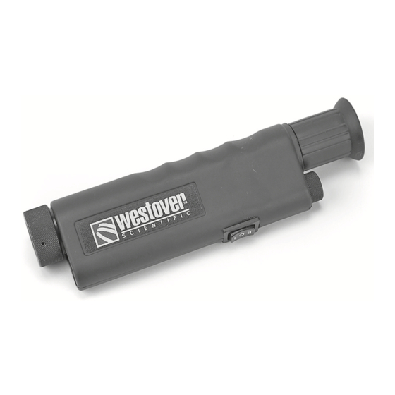
- Page 4 200X View Scope 6365-VS. DO NOT use when ™ connectors are illuminated by a laser source. 2.0 Connector and Protrusion Setting Tool Preparation On the 3M Protrusion Setting Tool, move the ™ actuator lever to the unactivated position as shown.
- Page 5 Remove the 3M Crimplok + Connector from the bag and remove the dust cap from the ferrule. Remove the ™ ™ lapping film disc from the bag and set it aside for later. Insert the connector into the SC port with the actuation cap facing upward. Ensure the connector is fully seated in the port.
- Page 6 For 900 µm, determine if the fiber is tight or semi- tight buffer. If the 900 µm slides easily from the fiber, it is semi-tight buffer fiber. If not, it is tight buffer. Break-out kits for 250 µm are semi-tight. Make note of tight or semi-tight for step 3.11.
- Page 7 Close the left cover. Close the right cover. Push the shuttle forward to cleave the fiber. Open the right cover. Use tweezers to carefully grab the glass shard. Discard it in the shard container. CAUTION: The glass shard is sharp and can pierce the skin.
- Page 8 3.11 Lay the fiber in the track running through the center of the fiber holder. Use the “TIGHT BUFFER” or “SEMI- TIGHT BUFFER” slits as appropriate. Reference section 3.3 to determine which fiber type. Tight buffer Semi-tight buffer 3.12 Move shuttle forward. Leave at least one finger width of buffer extending beyond the nozzle.
- Page 9 3.14 Rotate the fiber so the fiber curl is directed downward in the fiber holder. 3.15 Hold fiber at rear, and pull the fiber backward. Position the fiber so the tip is flush (±1 mm) with the Fiber tip fl ush end of the nozzle.
- Page 10 4.0 Fiber Insertion and Connector Activation Grip the back of the fiber holder. Do not grip the front or middle lids, because they may need to pop open. Slowly insert the fiber holder (with cleaved fiber) into SLOW, >5 seconds the guide track on the protrusion setting tool until it reaches a stop.
- Page 11 For 250 µm only, the fiber will bow in the nozzle slot. No lids will open with 250 µm. Note: Bowing these 3 different fiber coating types at 3 different lengths enables consistent fiber protrusion setting. 250 µm coating Rotate the activation lever on the protrusion setting tool 180°...
- Page 12 IS NOT crimped. A flush, even surface indicates the fiber IS crimped. Not crimped Crimped For 900 µm only. CRITICAL STEP: If you have the 3M 200X View Scope 6365-VS for end face ™ inspection, skip this step (4.8) until after step 5.8, connector cleaning is complete.
- Page 13 Remove the connector from the port on the protrusion setting tool. Use care to protect the ferrule and fiber tips from damage. 5.0 Nano-finishing and Cleaning Complete the installation process using the 3M Nano- ™ finisher. Open the lid on the finisher by first depressing the latch.
- Page 14 Failure to wet the disc results in poor connector performance. Insert the connector into the port on the 3M Nano-finisher lid making certain it is fully engaged. Push until a click ™...
- Page 15 Remove the lapping film. Inspect the lapping film for fiber tracks. If the film has tracks, dispose of it. If not, restart at step 5.1. Dry the connector using a new lint-free wipe. Do not use the same wipe used for stripping fiber. Fold the wipe to provide cushion.
- Page 16 Before the network has a laser light source feeding Chips or cracks inside the 1/2 diameter circle are not allowed. your connector, inspect the fiber end face with 3M ™ 200X View Scope 6365-VS if you have one. If the...
-
Page 17: Troubleshooting
6.0 Connector Reusability Should it become necessary to separate the connector and fiber, e.g. to reset the fiber protrusion, the activation cap within the connector can be deactivated. This is accomplished by first removing the connector from the port on the protrusion setting tool. Place the connector atop the deactivation station on the tool base, with the activation cap face up, and press firmly downward. - Page 18 Warranty; Limited Remedy; Limited Liability. This product will be free from defects in material and manufacture for a period of one (1) year from the time of purchase. 3M MAKES NO OTHER WARRANTIES INCLUDING, BUT NOT LIMITED TO, ANY IMPLIED WARRANTY OF MERCHANTABILITY OR FITNESS FOR A PARTICULAR PURPOSE.


Need help?
Do you have a question about the Crimplok 8700-PS/APC and is the answer not in the manual?
Questions and answers