Advertisement
Quick Links
Industrial Loadbreak Elbow
200 A
25 kVClass
5811 Series
Installation Instructions
1.0 General
The 3M
™
Industrial Loadbreak Elbow connector is a fully-
shielded and insulated plug-in termination for connecting
underground cable to transformers, switching cabinets and
junctions equipped with loadbreak bushings. The elbow
connector and bushing insert comprise the essential
components of all loadbreak connections.
The coppertop (bimetal) compression connector is a
standard item to transition from the cable to the loadbreak
probe. An aluminum crimp barrel is inertia-welded to a
copper lug. The aluminum barrel makes the connector
easy to crimp and the copper lug ensures a reliable, tight,
cool operating connection with the loadbreak probe.
2.0 Installation
Cable stripping and scoring tools, available from various
tool manufacturers, are recommended for use when
installing loadbreak elbows. After preparing the cable and
installing shield adapter, the elbow housing is pushed onto
the cable. The loadbreak probe is threaded into the
coppertop connector using the supplied installation tool or
an approved equivalent. Use a shotgun stick to perform
loadmake and loadbreak operations. (See page 10 for
operating instructions.)
Kit Contents:
• Elbow Body
• Coppertop Compression Connector
• Loadbreak Probe
• Probe Installation Tool
• Silicone Lubricant
• Cold Shrink Jacketing Tube
• Mastic Strips (3 ea.)
• Ground Braid Assembly
• Constant Force Spring
• CC-3 Cable Cleaning Pads
• Installation Instructions
These instructions do not claim to cover all details or variations in the equipment, procedure, or process described, nor to provide directions for meeting every
contingency during installation, operation, or maintenance. When additional information is desired to satisfy a problem not covered sufficiently for the user's
purpose, please contact your 3M sales representative.
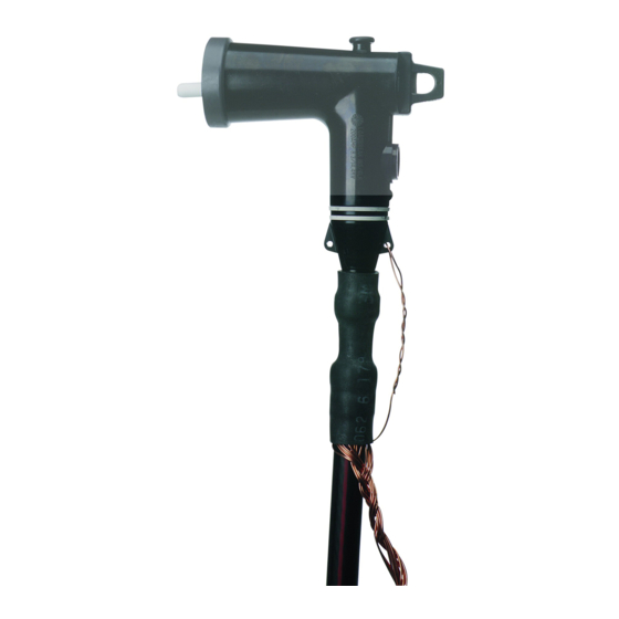
Figure 1.
Illustration of a completely assembled 25 kV loadbreak elbow,
shown on tape shielded cable.
Advertisement

Related Manuals for 3M 5811 Series


Summary of Contents for 3M 5811 Series
- Page 1 These instructions do not claim to cover all details or variations in the equipment, procedure, or process described, nor to provide directions for meeting every contingency during installation, operation, or maintenance. When additional information is desired to satisfy a problem not covered sufficiently for the user’s purpose, please contact your 3M sales representative.
-
Page 2: Installation Notes
Installation Notes: • Cable description (check kit selection table on page 3 • Crimping Tool (check crimp chart on page 9) • Location • Installation comments 78-8124-4544-9-B... - Page 3 Table 1. Kit Selection Table for 25 kV Class Kit No. Insulation Diameter Range 25kV (AWG/kcmil) 100% 133% (260 mils) (320 mils) Inches (mm) Stranded Compact/Solid Stranded Compact/Solid 5811-B* 0.700–0.910 2–1 5811-B-3 (17.8–23.1) 5811-B-2 5811-C* 1–3/0 1/0–4/0 2–1/0 2–1/0 5811-C-3 5811-C-2 0.850–1.100 5811-C-1...
- Page 4 3.0 Preparation of Tape Shield Cable 3.1 Check to be sure cable size fits within the kit range as shown in Table 1, page 3. • Remove cable jacket for 8 ⁄ " (210 mm). 3.2 Remove metallic tape shield, leaving 1 ⁄...
- Page 5 4.0 Preparation of Wire Shield Cable 4.1 Check to be sure cable size fits within the kit range as shown in Table 1, page 3. • Remove cable jacket for 8 ⁄ " (210 mm). 4.2 Cut-off shield wires, leaving 1 ⁄...
- Page 6 ® 5.0 Preparation of UniShield Cable 5.1 Check to be sure cable size fits within the kit range as shown in Table 1, page 3. Note: UniShield cable has compact conductor. • Mark cable jacket 7" (178 mm) from cable end (a temporary wrap of vinyl tape can be used as a marker). •...
- Page 7 6.0 Preparation of Jacketed Concentric Neutral Cable Note: The ground braid assembly and constant force spring are not used for this application. 6.1 Check to be sure cable size fits within the kit range as shown in Table 1, page 3. •...
-
Page 8: Elbow And Loadbreak Probe Installation
Do not overlap crimps. Place as many crimps on the connector as will fit. • Clean excess inhibitor grease from coppertop connector by wiping toward threaded eye. • Clean cable insulation with solvent pad(s) from 3M CC-3 Cable Cleaning Kit. Do Not allow solvent to touch cable semi-con. - Page 9 Clean and Lubricate Attach Ground Lead to Elbow Grounding Tab Step Step 1/2" (13 mm) Mastic Strip Cold Shrink Tubing Counter-Clockwise 7.5 Remove white liners from remaining mastic strip and apply around base of elbow, ⁄ " (13 mm) from step as shown.
- Page 10 8.0 Operating Instructions 8.1 Before Loadmake or Loadbreak Operation: Area must be clear of obstructions or contaminants that would interfere with the operation of the connector. This position should allow you to establish firm footing and enable you to grasp the shotgun stick securely, maintaining positive control over the movement of the loadbreak connector before, during and directly after the operating sequence.
- Page 11 78-8124-4544-9-B...
- Page 12 MERCHANTABILITY OR FITNESS FOR A PARTICULAR PURPOSE. If this product is defective within the warranty period stated above, your exclusive remedy shall be, at 3M’s option, to replace or repair the 3M product or refund the purchase price of the 3M product. Except where prohibited by law, 3M will not be liable for any loss or damage arising from this 3M product, whether direct, indirect, special, incidental or consequential regardless of the legal theory asserted.
Need help?
Do you have a question about the 5811 Series and is the answer not in the manual?
Questions and answers