Advertisement
Quick Links
3M
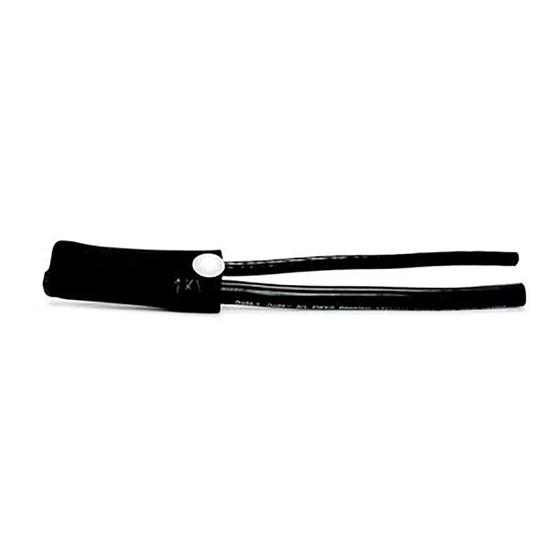
Motor Lead Pigtail Splice
™
5321, 5322, 5323 & 5324
for 5/8 kV Non-Shielded and Shielded Cables
(Ribbon or Wire and UniShield
Instructions
Cable Size Range:
Feeder: #8 AWG – 500 kcmil
Motor Lead: #10 AWG – 500 kcmil
Copper Conductors
CAUTION
Working around energized systems may cause serious injury or death. Installation should
be performed by personnel familiar with good safety practice in handling electrical
equipment. De-energize and ground all electrical systems before installing product.
August 2009
78-8096-4635-5-C
Cables)
®
Advertisement

Subscribe to Our Youtube Channel
Summary of Contents for 3M 5321
- Page 1 Motor Lead Pigtail Splice ™ 5321, 5322, 5323 & 5324 for 5/8 kV Non-Shielded and Shielded Cables (Ribbon or Wire and UniShield Cables) ® Instructions Cable Size Range: Feeder: #8 AWG – 500 kcmil Motor Lead: #10 AWG – 500 kcmil...
- Page 2 Kit Selection Table Cable Size Range (AWG/kcmil) Cable Insulation Kit Number Max Bolt Length O.D. Range Feeder Motor Lead 5321 8 – 4 10 – 4 0.30 – 0.51 in. 1/2 in. 5322 2 – 1/0 4 – 1/0 0.43 – 0.65 in.
-
Page 3: Tape 130C (Figure
1.2 Remove cable insulation for length recommended by terminal lug manufacturer; if no information is available, remove for depth of lug barrel. 2.0 Install Lugs 2.1 Install and crimp lugs per manufacturer’s direction. See back page if 3M Scotchlok Lugs are used. - Page 4 2.5 FOR 8 kV ONLY. Cover the lugs and bolt with four half-lapped layers of Scotch Linerless Rubber Splicing ® Tape 130C (Figure 3). Scotch Linerless Rubber Splicing Tape 130C ® Figure 3 NOTE: FOR 8 kV ONLY: Lug cover will be printed with 5 kV rating, but mastic layer in Step B–5 (Figure 3) qualifies the part as 8 kV.
- Page 5 4.0 Install Cold Shrink Insulator 4.1 Install Cold Shrink by sliding it over the Lug Cover with the loose end tab at terminal lug end. Align the end of the Cold Shrink Tube approximately 2 beyond the Mastic Seal and Vinyl Seal Tape. Remove core by unwinding counter-clockwise (Figure 6).
- Page 6 NOTE: Grounding If practice calls for an external ground, a 3M Ground Strap Assembly Kit (GS–1, GS–2 and GS–3) is available from your local distributor for use on ribbon shield cable. Follow procedure for these kits for grounding. For UniShield and wire shield cable, a ground strap assembly kit is not necessary.
- Page 7 For Ribbon Shielding 2" 1/4" Scotch Stress Control Tape 2220 ® Figure 8a For Wire Shielding 2" 1/2" 1" 1/4" Scotch Stress Control Tape 2220 ® Figure 8b 2" For UniShield ® 1/2" 1/2" Scotch Stress Control Tape 2220 ® Figure 8c 6.2 Wrap two half-lapped layers of vinyl tape over the Scotch Stress Control Tape 2220 and one inch onto cable...
- Page 8 Scotch Super 33+™ Vinyl Electrical Tape ® Figure 9c 7.0 Install Lugs 7.1 Install and crimp lugs per manufacturer’s direction; see back page if 3M Scotchlok Lugs are used. ™ ™ 7.2 FOR 8kV ONLY. Fill lug/insulation gaps with Scotch Linerless Rubber Splicing Tape 130C (Figure 10).
-
Page 9: Installation
7.4 FOR 8 kV ONLY. Cover the lugs and bolt with four half-lapped layers of Scotch Linerless Rubber Splicing ® Tape 130C (Figure 12). Scotch Linerless Rubber Splicing Tape 130C ® Figure 12 8.0 Installation 8.1 Install Lug Cover (Figure 13). NOTE: The lug cover must extend over the cable insulation by a minimum of 1". - Page 10 9.0 Install Cold Shrink Insulator 9.1 Install Cold Shrink Insulator by sliding it over the Lug Cover with the loose core end tab at terminal end. Align the end of the Cold Shrink Insulator so it covers the vinyl tape on the feeder cable. Remove core by unwinding counter-clockwise (Figure 15).
- Page 11 Tooling Index Lug and Crimping Information for 3M Scotchlok Copper Lugs ™ ™ 30014 thru 30045 31145 thru 31166 One hole Two hole Copper Lugs CRIMPING TOOL-DIE SETS (NUMBER OF CRIMPS) ™ Square D Co. Scotchlok ™ Burndy Corporation Thomas & Betts Corporation...
- Page 12 Warranty; Limited Remedy; Limited Liability. This product will be free from defects in material and manufacture for a period of one (1) year from the time of purchase. 3M MAKES NO OTHER WARRANTIES INCLUDING, BUT NOT LIMITED TO, ANY IMPLIED WARRANTY OF MERCHANTABILITY OR FITNESS FOR A PARTICULAR PURPOSE.


Need help?
Do you have a question about the 5321 and is the answer not in the manual?
Questions and answers