Advertisement
Quick Links
3M
Cold Shrink QT-III Silicone
™
Rubber Skirted Termination Kit
With High-K Stress Relief
For Tape Shielded, Wire Shielded and UniShield
7620-S-2
Instructions
IEEE Std. No. 48
Class 1 Termination
5/8 kV Class
95 kV BIL
F CAUTION
Working around energized systems may cause serious injury or death. Installation should
be performed by personnel familiar with good safety practice in handling electrical
equipment. De-energize and ground all electrical systems before installing product.
May 2013
78-8117-0508-2 Rev D
Cable
®
3
Advertisement

Related Manuals for 3M 7620-S-2


Summary of Contents for 3M 7620-S-2
- Page 1 Cold Shrink QT-III Silicone ™ Rubber Skirted Termination Kit With High-K Stress Relief For Tape Shielded, Wire Shielded and UniShield Cable ® 7620-S-2 Instructions IEEE Std. No. 48 Class 1 Termination 5/8 kV Class 95 kV BIL F CAUTION Working around energized systems may cause serious injury or death. Installation should be performed by personnel familiar with good safety practice in handling electrical equipment.
-
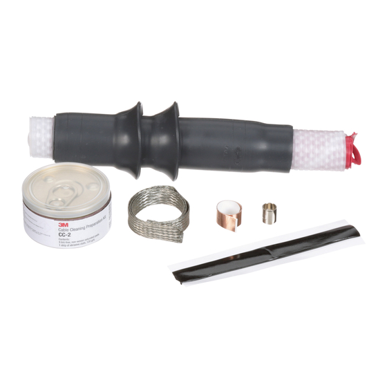
Page 2: Kit Contents
3 High–K, Tracking Resistant, Silicone Rubber Terminations 3 Preformed Ground Braids 3 Constant Force Springs 3 3M™ EMI Copper Foil Shielding Tape 1181 Strips, 1/2" x 10" 6 Strips Scotch Mastic Strip 2230 (black with white release liners, bagged) ®... -
Page 3: Prepare Cable
2.2 Prepare cable using dimensions shown in Figure 1. BE SURE TO ALLOW FOR DEPTH OF TERMINAL LUG. If necessary to prevent tape shield from unrolling, hold down edge with a single wrap of 3M™ EMI Copper Foil Shielding Tape 1181. - Page 4 3.2 Position pre-formed ground braid with short tail over tape shield directly adjacent to cable jacket cut edge. PLEASE NOTE: The ground braid needs to make full contact with the metallic tape shield. Position long tail of ground braid, extending over cable jacket with solder block over mastic strip (Figure 3). Secure ground braid to cable jacket 3 1/2"...
- Page 5 3.3 Wrap ground braid around cable tape shield one complete wrap, trim excess to prevent overlap and secure in place with constant force spring. Wrap spring in same direction as ground braid (Figure 4). Cinch (tighten) the spring after wrapping the final winding. Mastic Strip 2230 from kit and remove white release liners.
- Page 6 Important Packaging Notice In order to make sure that you receive an undamaged termination, this 3M™ Cold Shrink QT-III Termination is packed with a RED SHIPPING CORE inside of the white core. Please remove the red shipping core BEFORE you install the ter- mination.
- Page 7 6.2 Connect ground braid to system ground according to standard practice. Correct Installation of Termination on Tape Shielded Cable Vinyl Tape Marker Ridge at End of Cable Insulation Shield (Semi-Con) Ridge at End of Stress Controlling Compound Semi-Con Insulation Shield Cable Insulation Environmental Top Seal...
- Page 8 Instructions for Wire Shielded Cable 7.0 Prepare Cable 7.1 Check to be sure cable size fits within kit range as shown in Table 1. 7.2 Prepare cable using dimensions shown in Figure 8 and Figure 9. BE SURE TO ALLOW FOR DEPTH OF TERMINAL LUG.
- Page 9 8.0 Install Ground Braid 8.1 Select a Scotch Mastic Strip 2230 from kit and remove white release liners. Using light tension, apply a ® SINGLE WRAP of mastic around the cable jacket 1/4" (6 mm) from cut edge (Figure 10). Cut off excess. 1/4"...
- Page 10 Constant Force Spring Trim Shield Wires Ground Braid Scotch® Mastic Strip 2230 Cable Wire Solder Block Shield Scotch® Mastic Strip 2230 Ground Braid Leg Figure 12 8.5 Wrap two highly stretched half-lapped layers of electrical grade vinyl tape around mastic seal, constant force spring and exposed shield wires (Figure 13).
- Page 11 Important Packaging Notice In order to make sure that you receive an undamaged termination, this 3M™ Cold Shrink QT-III Termination is packed with a RED SHIPPING CORE inside of the white core. Please remove the red shipping core BEFORE you install the ter- mination.
- Page 12 Correct Installation of Termination on Wire Shielded Cable Vinyl Tape Marker Ridge at End of Cable Insulation Shield (Semi-Con) Ridge at End of Stress Controlling Compound Cable Insulation Semi-Con Insulation Shield Environmental Top Seal Stress Controlling Compound Conductor Silicone Rubber Tube Instructions for UniShield Shielded Cable ®...
- Page 13 12.4 Remove constant force spring. Bend shield wires back upon cable jacket 1" (25 mm). Cut excess shield wire and discard (Figure 17). Depth Of Terminal Lug + Growth Allowance 6 3/4" (171 mm) 1" (25 mm) Semi-Conductive Jacket Fold Back Shield Wires Figure 17 12.5 Remove semi-conductive jacket to dimension shown in Figure 18.
- Page 14 13.0 Install Ground Braid 13.1 Select a Scotch Mastic Strip 2230 from kit and remove white release liners. Using light tension, apply a ® SINGLE WRAP of mastic around the cable semi-conductive jacket 1/4" (6 mm) from shield wires (Figure 19). Cut off excess.
- Page 15 Mastic Strip 2230 from kit and remove white release liners. Apply a second SINGLE 13.4 Select second Scotch ® WRAP of mastic over solder block on ground braid and previously applied mastic (Figure 21). Cut off excess. Constant Force Spring Shield Wires Ground Braid Trim...
- Page 16 Important Packaging Notice In order to make sure that you receive an undamaged termination, this 3M™ Cold Shrink QT-III Termination is packed with a RED SHIPPING CORE inside of the white core. Please remove the red shipping core BEFORE you install the ter- mination.
- Page 17 Correct Installation of Termination on UniShield Shielded Cable ® Vinyl Tape Marker Ridge at End of Cable Insulation Shield (Semi-Con) Ridge at End of Stress Controlling Compound Cable Insulation Semi-Con Environmental Top Seal Conductor Stress Controlling Compound Silicone Rubber Tube 78-8117-0508-2 Rev D...
- Page 18 Tooling Index Lug and Crimping Information for 3M Scotchlok Copper Lugs ™ ™ 31145 thru 31178 30014 thru 30045 31036 thru 31068 Two hole-long barrel One hole One hole-long barrel Crimping Tool-Die Sets (Minimum Number Of Crimps) ™ Square D Co.
- Page 19 Tooling Index Lug and Crimping Information for 3M Scotchlok Copper/Aluminum Lugs ™ ™ 40016 thru 40079 40132 thru 40178 One hole Two hole Crimping Tool-Die Sets (Minimum Number Of Crimps) Kearny Square D Co. Burndy Corporation Thomas & Betts Corporation Blackburn Nat’l...
- Page 20 INCLUDING, BUT NOT LIMITED TO, ANY IMPLIED WARRANTY OF MERCHANTABILITY OR FITNESS FOR A PARTICULAR PURPOSE. If this product is defective within the warranty period stated above, your exclusive remedy shall be, at 3M's option, to replace or repair the 3M product or refund the purchase price of the 3M product.
Need help?
Do you have a question about the 7620-S-2 and is the answer not in the manual?
Questions and answers