
Subscribe to Our Youtube Channel
Related Manuals for 3M 8800 APC/AS


Summary of Contents for 3M 8800 APC/AS
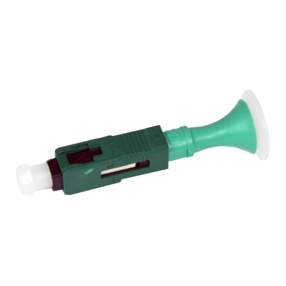
- Page 1 No Polish Connector 8800-APC/AS ™ SM SC/APC, Angle Splice, 250/900-µm Instructions October 2010 78-8140-1581-0-C...
-
Page 2: Table Of Contents
Protective Eyewear c C AUTION Safety glasses should be worn when handling chemicals and cleaving the optical fiber Chemical Precautions c W ARNING Storage, use and disposal of isopropyl alcohol should be per your company health, safety and environmental instructions. Refer to material safety data sheet for health hazards, safe handling, proper use and control measures. c C AUTION Product contains phenylmethyl silicone (63148-58-3), hydrophobic silica (68611-44-9) and may cause minimal eye irritation. Avoid contact with eyes and wash hands before eating or smoking. Upon eye contact, immediately flush eyes with water while holding eyelids open and continue flushing for ten minutes. Contact a physician. Upon skin contact, wash with soap and water. Product Information: Material Safety Data Sheet or 3M Company, St. Paul MN, 55144-1000, (651) 733-1110 Operator 55 Bare Fiber Handling c C AUTION Cleaved glass fibers are sharp and can pierce the skin. Use tweezers when handling shards and dispose of them properly per your company health and safety instructions. Fiber/Cable Handling c C AUTION Optical fiber can be damaged by excessive tensile, compressive and bending forces. Consult the manufactures' specifications for proper handling instructions. Laser Safety c C AUTION Take the proper precautions when working with optical fiber because invisible laser light may be present. The principal laser hazard... -
Page 3: Summary
1.0 Summary 1.1 No Polish Connector 8800-APC/AS terminates 250 µm or 900 µm single fi bers with SC/APC interface and ™ angle splice for superior optical return loss performance. 1.2 Required tools, which are available in the 3M Fiber Optic Angle Cleave Kit 2565. ™ Fiber Optic ™ Angle Cleaver 2535 Lint-Free Cloths Isopropyl No Polish Connector ™ Alcohol Fiber Shard Assembly Tool Container 8865-AT Fiber Holder ™ Fiber Stripper 6365-KS ™ 1.3 For situations where a suitable work area is not available, the case and plastic plate, which are included in the 2565 kit, can create a work surface. The case can be set on level ground, on a vehicle, or hung by the hook and... -
Page 4: Connector Preparation
2.0 Connector Preparation 3.0 Fiber Preparation 2.1 Prior to each termination, clean all tools, including 3.1 Open all three angle cleaver clamps and levers. fiber holder, with a lint-free cloth and reagent-grade isopropyl alcohol. 3.2 Carefully clean the cleaver clamps using a small 2.2 Carefully remove connector body from the bag. brush. Remove the dust caps from the front and rear of the connector body. 2.3 Open the actuator button on the assembly tool base. Insert connector into coupling in the tool with white actuation cap facing upwards, pushing forward until it clicks. 3.3 For 900 µm buffer fiber, cut the buffer. If the 900 µm slides easily from the fiber it is loose tube or semi- tight buffered fiber. - Page 5 In this instance, use the fiber holders' clamp to 3.6 Clean fiber with alcohol and lint-free cloth. prohibit the buffer from moving or stretching during the stripping process. Place the fiber into the fiber holder groove, labeled "semi-tight", with the fiber to be stripped protruding from the back of the holder. Close the clamp and proceed to strip and clean the fiber. Once complete, remove the fiber from the holder. If the 250 µm fiber still moves inside the 900 µm buffer after it is clamped in the "semi-tight" groove, then the connector must be installed on the 250 µm fiber. Strip at least eight inches (203 mm) of the 900 µm buffer and complete the installation. Semi-Tight Buffered Fibers 3.7 With the two covers and clamp open, place the assembly tool fiber holder onto the cleaver. Push the holder toward the cleaver blade until it stops. 3.4 For all fibers, strip the 900 µm and 250 µm coatings exposing glass for 1.67" to 1.77" (42.5 mm to 45 mm). 3.8 Place fiber in angle cleaver so that the coating edge is at 8.0 ± 0.5 mm. Note: Make sure that the natural bow in the fiber is facing down and laying properly in the bottom of V-groove in both cleaver clamps 1 & 2. Coating edge at 8.0 mm 3.5 To verify the correct strip length, use the white marks on the left side of the cleaver. Align the coating edge to the left edge of the cleaver and the fiber tip should be between the two white lines.
- Page 6 3.9 Close the cleaver clamp #1 first. This process sets the 3.12 Close the two covers and the clamp on the fiber holder. appropriate cleave length. The funnel cover will not close completely while in the cleaver. Do not force or cover can break. funnel cover 3.10 Close the cleaver clamp #2. 3.13 Depress cleave activation lever (#3) and hold it down until Note: Ensure there is no fiber bow between the two clamps. If there Clamp #2 slide assembly has fully moved to the right, is a bow, open both clamps and repeat steps 3.9 and 3.10. indicating that the angle cleave is complete. 3.11 For 250 µm fiber and tight buffer 900 µm fiber, the fiber should be placed in the fiber holder tool groove which Note: If fiber does not break immediately upon activation, is labeled “Tight buffer”. For semi-tight buffer fiber, or it breaks so that the cleave length is not 8 mm, it should be placed in the groove labeled “Semi-tight then open clamps and carefully clean the cleaver buffer”. This provides the proper clamping force on the clamps with a brush and alcohol-soaked lint-free 900 µm buffer. cloth. Cut exposed fiber and strip, clean and cleave again. If issues persist, rotate cleaver blade to the next position using the supplied wrenches and Tight buffer try again. 3.14 Open cleaver clamp #1 and remove fiber holder and fiber from cleaver. Note: Do not open activation lever after cleaving until fiber holder and fiber have been removed.
-
Page 7: Fiber Insertion
3.15 Verify the 8 mm cleave length again by using the length 4.2 Place fiber holder in the assembly tool base. gauge on the assembly base. The 8 mm cleave length is measured from the end of the 900 µm buffer to the end of the cleaved fiber. On semi-tight buffer fiber, the 250 µm coating may protrude 1 mm past the 900 µm semi-tight buffer. Re-strip, clean and cleave the fiber if necessary to meet length requirements. 4.3 VERY SLOWLY slide the fiber holder towards the connector. A bow in the fiber is started once the white line on the fiber holder is even with the white line (BOW START) on the base. If a bow is not seen, strip, clean and cleave the fiber as shown in section 3 and try installation again. 3.16 Open activation lever #3 and clamp #2 of angle cleaver. Slide very slowly Dispose of fiber shard per company practice. Bow Start Note: See photo in 4.4 for more detail. 4.0 Fiber Insertion 4.4 If a bow is seen before the white line on the holder meets the white line on the base, then strip, clean, and cleave the 4.1 Slide the fiber holder’s guide funnel fully forward and close fiber as shown in Section 3 and try again. the funnel cover. An audible click can be heard. Check for proper cleave length again by inspecting the amount of fiber protruding beyond the funnel end of the holder. The amount of exposed fiber should be from 0 to 1 mm (0.04"). When white lines meet, Fiber Bow should start. -
Page 8: Splice Actuation
5.4 Slide fiber holder from actuation tool. 5.0 Splice Actuation 5.1 While there is a fiber bow, press actuator button firmly to actuate the splice. An audible click will be heard when properly completed. Note: If continuity verification is required or you need to test the link prior to placing in service you will perform this step now. Do not proceed to step 5.2 until testing is complete. If re-termination is required, please skip to Section 6, 3M No Polish ™ Optional: 3 M No Polish Connector can be tested in the tool ™ Connector (NPC) Re-termination. using a SC coupling. 5.5 Pull connector from coupling and clean connector end face with isopropyl alcohol and a lint-free cloth. 5.2 Press release lever to allow forward motion of funnel. Push ears to move funnel forward and actuate buffer clamp. 5.6 A fter removing connector from the coupling, replace the dust cap on the ferrule until connector is ready to be placed in service. - Page 9 6.0 3M No Polish Connector (NPC) Remove fiber and insert connector with the actuation ™ Re-termination cap facing up in the coupling, pushing forward until it clicks. Follow steps 3.0 through 5.1 to re-terminate 6.1 To re-terminate the NPC connector, remove the connector the NPC connector. from the coupling on the actuation tool and fiber holder prior to activating the buffer clamp at the boot. Take the 6.3 Upon verification that connector has been terminated cap popper provided for you in the box of NPC connectors satisfactorily, slide the fiber holder up into the back of and place it in the three slots provided on the underside of the boot. Return to steps 5.2 through 5.6 to complete the the NPC connector shell as shown. termination of the NPC connector. 6.2 Firmly press the cap popper into the NPC connector shell For information regarding the proper field testing until the activation cap is depressed. procedure refer to the Tech Tip on the 3M CMD website, www.3m.com/telecom...
- Page 10 Warranty; Limited Remedy; Limited Liability. This product will be free from defects in material and manufacture for a period of one (1) year from the time of purchase. 3M MAKES NO OTHER WARRANTIES INCLUDING, BUT NOT LIMITED TO, ANY IMPLIED WARRANTY OF MERCHANTABILITY OR FITNESS FOR A PARTICULAR PURPOSE.
Need help?
Do you have a question about the 8800 APC/AS and is the answer not in the manual?
Questions and answers