Table of Contents
Advertisement
Quick Links
3M
TM
Cold Shrink QS-III
Splicing Kit 5467A-We
Instructions
IEEE Std. 404
35 kV Class
250 kV BIL
* Splices (including size transitions) can be made to smaller or larger conductors (but larger
Jacketed Concentric Neutral (JCN)
Concentric Neutral (CN)
Kit Number
5467A-We
conductors may require special neutral handling), provided both cables are within the Insulation
O.D. Range and the connector meets the dimensional requirements shown below.
Connector Dimensional Requirements
Outside Diameter
Length
Aluminum (Al/Cu)
Length
Copper (Cu)
Selection Chart
Cable Insulation
O.D. Range
1.07" to 1.70"
(27,2 mm to 43,2 mm)
Minimum
Maximum
inches (mm)
inches (mm)
0.51" (13,0 mm)
1.70" (43,2 mm)
6.00" (152 mm)
------
------
6.50" (165 mm)
3M
™
QS-III Splicing Kit
5467A-We
78-8141-4631-8-A
CAUTION
Working around energized high-voltage systems may cause serious
injury or death. Installation should be performed by personnel familiar
with good safety practice in handling high-voltage electrical equipment.
De-energize and ground all electrical systems before installing product.
Conductor
Size Range
1/0 AWG - 350 kcmil*
(60 - 185 mm
2
)
Cold Shrink
Advertisement
Table of Contents

Related Manuals for 3M Cold Shrink QS-III Splicing Kit


Summary of Contents for 3M Cold Shrink QS-III Splicing Kit
- Page 1 Cold Shrink QS-III Splicing Kit 5467A-We Instructions IEEE Std. 404 35 kV Class 250 kV BIL Selection Chart Kit Number Cable Insulation Conductor O.D. Range Size Range 1/0 AWG - 350 kcmil* 5467A-We 1.07" to 1.70" (60 - 185 mm (27,2 mm to 43,2 mm) * Splices (including size transitions) can be made to smaller or larger conductors (but larger conductors may require special neutral handling), provided both cables are within the Insulation...
-
Page 2: Table Of Contents
Contents Kit Contents ............................3 Instructions for Jacketed Concentric Neutral (JCN) and Concentric Neutral (CN) Cables ....4 2.1 Prepare Cables..........................5 2.2 Install Splice ..........................7 For JCN to JCN Splices 2.3 Connect Neutral Wires for JCN Splices..................10 2.4 Install Jacket for JCN Splices......................11 For CN to CN Splices 2.5 Connect Neutral Wires for CN Splices ..................12 2.6 Install Jacket for CN Splices ......................13... -
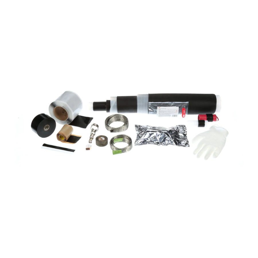
Page 3: 1.0 Kit Contents
1.0 Kit Contents: Kit Contents are as follows: f) Scotch® Rubber Mastic Tape 2228 Rolls (2 ea.) a) 3M™ Cold Shrink QS-III Splicing Kit 5467A (1 ea.) Cable Cleaning Pad Kit CC-3 (1 ea.) g) 3M b) Cold Shrink Jacketing Tube (1 ea.) ™... -
Page 4: Instructions For Jacketed Concentric Neutral (Jcn) And Concentric Neutral (Cn) Cables
2.0 Instructions for Splicing Jacketed Concentric Neutral (JCN), Concentric Neutral (CN) Cables, and JCN to CN Transition Splices Jacketed Concentric Neutral (JCN) Concentric Neutral (CN) Cable Jacket Cold Shrink Jacket Tape Marker Connector Cable Semi-con Splice Body Cable Insulation Rubber Mastic Seal Cutaway view (JCN) 78-8141-4631-8-A... -
Page 5: Prepare Cables
Prepare Cables 2.1.1 Prepare cables according to standard procedures. Refer to template provided or illustration below for proper dimensions. Additional distance is required on one cable to provide extra neutral wire length for connecting the neutrals. 13" (330 mm) 13" (330 mm) 4 1/2"... - Page 6 2.1.2 JCN: Carefully bend neutral wires back over edge of cable jackets. Press them against cables and temporarily secure with vinyl tape. For CN splices with exposed neutral connections: Carefully bend neutral wires back over binding (wire or tape). Press them against cables and temporarily secure with vinyl tape.
- Page 7 Aluminum Connector (Al / Cu) Copper Connector (Cu) Aluminum (Al/Cu) Connector Growth Chart Conductor Size Typical growth allowance (per end) 1/0 - 3/0 1/8" (3 mm) 4/0 - 350 1/4" (6 mm) Note: 1) Copper connectors do not require a length change allowance. 2) Maximum aluminum connector crimped length allowed is 6.50"...
-
Page 8: Install Splice
Install Splice 2.2.1 Install connector. See table (on cover) for proper connector dimensions. (For standard 3M™ connectors, refer to table at the end of this instruction for crimping information) 2.2.2 Apply a tape marker to semi-con insulation shield on cable which does not contain splice. - Page 9 2.2.4 Clean cables using standard practice: a. Do not use solvent or abrasive on cable semi-conductive insulation shield. b. If abrasive is used on cable insulation, do not reduce diameter below the 1.07" (27,2 mm) minimum specified for the splice. 2.2.5 Apply red compound on cable insulation, making certain to fill in edge of cable semi-cons.
-
Page 10: For Jcn To Jcn Splices
For JCN to JCN Splices Connect Neutral Wires for JCN Splices 2.3.1 Route neutrals straight across the splice body and secure using vinyl tape. 2.3.2 Wrap the neutral pad over one end of the splice and cable semi-con. Secure pad with two wraps of vinyl tape. -
Page 11: Install Jacket For Jcn Splices
For JCN to JCN Splices Install Jacket for JCN Splices Note: Jacketing is not optional. 2.4.1 Wrap a roll of slightly stretched rubber mastic over, centered on, each mastic seal. Tear off the last couple inches of mastic. Mastic Seal 2.4.2 Begin to install the cold shrink tube by completely covering the rubber mastic, and slowly pulling and unwinding the inner core counterclockwise toward the splice body. -
Page 12: For Cn To Cn Splices
2.4.3 Continue to install the cold shrink tube over the rubber mastic on the other cable by slowly pulling and unwinding the outer core counterclockwise. This portion of the cold shrink tube installs differently than typical cold shrink products in that as the tube shrinks, the end rolls under. The tube may need a slight push to get over the second mastic seal. -
Page 13: Install Jacket For Cn Splices
For CN to CN Splices Note: If grounding splice, leave sufficient neutral wire length to extend neutral wires through the inline compression connectors for connection to the ground wire per Wisconsin Electric specifications. 2.5.2 Connect the neutral wires using inline compression connectors. The neutral wires should pass through the connector, making an overlap crimp. - Page 14 For CN to CN Splices 2.6.2 Begin to install the cold shrink tube by completely covering the rubber mastic, and slowly pulling and unwinding the inner core counterclockwise toward the splice body. The outer core should remain relatively stationary while unwinding the inner core. If the outer core begins to move towards the first mastic seal, gently pull the outer core and jacketing tube towards the second mastic seal and continue unwinding the inner core.
-
Page 15: For Cn To Jcn Transition Splices
For CN to JCN Transition Splices Connecting Neutral Wires for Transition Splices 2.7.1 Wrap the neutral pad over one end of the splice and cable semi-con. Secure pad with two wraps of vinyl tape. Wrap a mastic strip around each cable semi-con next to the neutral wires. Neutral Pad Mastic Strip Neutrals straight across splice... -
Page 16: Install Jacket For Transition Splices
For CN to JCN Transition Splices Install Jacket for Transition Splices Note: Jacketing is not optional. 2.8.1 Wrap a roll of slightly stretched rubber mastic over, centered on, each mastic seal. Tear off the last couple inches of mastic. mastic seal rubber mastic torn-off end... -
Page 17: Connector Crimping Information
Crimping Tool – die Sets (number of crimps/end) Square Conductor D Co. 3M™ Bundy Corporation Thomas & Betts Corp. Kearney Size Anderson Scotchlok™ AWG or Div. Connector kcmil Y35, Y39, VC6-3** MY29 Y34A Y1000** TBM 5 TBM 8 TBM 12... - Page 18 LIMITED TO, ANY IMPLIED WARRANTY OF MERCHANTABILITY OR FITNESS FOR A PARTICULAR PURPOSE. If this product is defective within the warranty period stated above, your exclusive remedy shall be, at 3M’s option, to replace or repair the 3M product or refund the purchase price of the 3M product.
Need help?
Do you have a question about the Cold Shrink QS-III Splicing Kit and is the answer not in the manual?
Questions and answers