Table of Contents
Advertisement
Quick Links
Advertisement
Table of Contents

Related Manuals for Metrohm NIRS DS2500


Summary of Contents for Metrohm NIRS DS2500
- Page 1 NIRS DS2500 Analyzer Manual 8.922.8001EN / 2018-11-09...
- Page 3 Metrohm AG CH-9100 Herisau Switzerland Phone +41 71 353 85 85 Fax +41 71 353 89 01 info@metrohm.com www.metrohm.com NIRS DS2500 Analyzer Manual 8.922.8001EN / 2018-11-09...
- Page 4 Technical Communication Metrohm AG CH-9100 Herisau techcom@metrohm.com This documentation is protected by copyright. All rights reserved. This documentation has been prepared with great care. However, errors can never be entirely ruled out. Please send comments regarding possible errors to the address above.
-
Page 5: Table Of Contents
■■■■■■■■■■■■■■■■■■■■■■ Table of contents Table of contents 1 Introduction Instrument description ............1 Intended use ................. 2 About the documentation ........... 2 1.3.1 Symbols and conventions ............2 Safety instructions ..............3 1.4.1 General notes on safety ............3 1.4.2 Electrical safety ................ - Page 6 ■■■■■■■■■■■■■■■■■■■■■■ Table of contents 5 Maintenance Maintenance by Metrohm Service ........19 User maintenance ............... 19 5.2.1 Replacing the lamp ..............19 5.2.2 Replacing the fan filter ............30 5.2.3 Replacing the fuses ..............33 6 Technical specifications Interfaces ................35 Power connection ...............
- Page 7 ■■■■■■■■■■■■■■■■■■■■■■ Table of figures Table of figures Figure 1 Front NIRS DS2500 Analyzer .............. 5 Figure 2 NIRS DS2500 Analyzer rear ..............6 ■■■■■■■■...
-
Page 9: Introduction
■ Liquid samples: liquids or suspensions ■ The NIRS DS2500 Analyzer is a robust instrument that is resistant to mois- ture, dust, vibrations and temperature fluctuations. As a result, it can be operated in a variety of production facilities. The NIRS DS2500 Analyzer is operated with the control software via an external computer. -
Page 10: Intended Use
This instrument is suitable for measuring chemicals and flammable sam- ples. Therefore, the use of the NIRS DS2500 Analyzer requires the user to have basic knowledge and experience in handling toxic and caustic sub- stances. Knowledge regarding the application of fire prevention measures prescribed for laboratories is also mandatory. -
Page 11: Safety Instructions
1.4.2 Electrical safety Electrical safety when working with the instrument is ensured in compli- ance with international standard IEC 61010. WARNING Only personnel qualified by Metrohm are authorized to carry out service work on electronic components. ■■■■■■■■... -
Page 12: Flammable Solvents And Chemicals
■■■■■■■■■■■■■■■■■■■■■■ 1.4 Safety instructions WARNING Never open the housing of the instrument. The instrument could be damaged by this. There is also a risk of serious injury if live components are touched. There are no parts inside the housing which can be serviced or replaced by the user. -
Page 13: Overview Of The Instrument
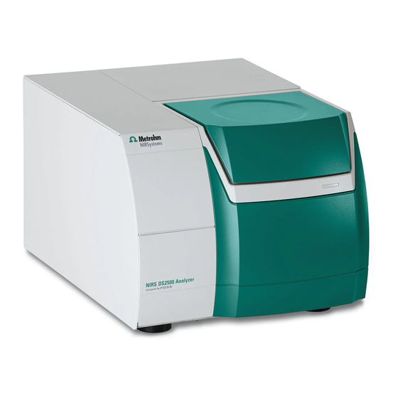
■■■■■■■■■■■■■■■■■■■■■■ 2 Overview of the instrument 2 Overview of the instrument Front Figure 1 Front NIRS DS2500 Analyzer Sampling window LED display Lamp compartment Feet (shock-absorbing) ■■■■■■■■... -
Page 14: Rear
■■■■■■■■■■■■■■■■■■■■■■ 2.2 Rear Rear Figure 2 NIRS DS2500 Analyzer rear On/off switch Fuse holder For switching the instrument on and off. Power socket Type plate Sealed with protective cap. LAN connection socket Sealed with protective cap. With filter. ■■■■■■■■... -
Page 15: Installation
3.1.3 Application area The NIRS DS2500 Analyzer is designed for offline use in the laboratory or atline use in the production process. Setting up the instrument Like most high-precision instruments, the NIRS DS2500 Analyzer is sensi- tive to ambient conditions, which may negatively influence its perfor- mance and shorten its service life. -
Page 16: General Conditions
Vibrations and shocks interfere with the sensitive optical and mechanical components and compromise calibration and measuring accuracy. Set up the NIRS DS2500 Analyzer at a stable workplace that does not propagate vibrations resulting from manual work (e.g. typing on the com- puter keyboard). -
Page 17: Connecting The Data Cable
5 Connect the other end of the power cord to the power grid. Connecting the data cable In order to control the NIRS DS2500 Analyzer, it is connected to a com- puter either directly or via a local network (LAN). -
Page 18: Switching On The Instrument
3.5 Switching on the instrument Switching on the instrument Switching on the instrument 1 Turn the on/off switch (2-1) to the position I. The LED display on the front of the NIRS DS2500 Analyzer (1-3) ■ lights up. The instrument performs a self-test. -
Page 19: Setting Up Accessories
■■■■■■■■■■■■■■■■■■■■■■ 3 Installation Setting up accessories Metrohm supplies various sample cups for your NIRS DS2500 Analyzer: Samples Sample cups Order number Nonhomogenous, solid samples in large DS2500 large sample cup 6.7402.050 quantities Nonhomogenous, solid samples in small Mini sample cup, 10 pieces 6.7402.030... -
Page 20: Analyzing Nonhomogenous, Solid Samples In Small Quantities
■■■■■■■■■■■■■■■■■■■■■■ 3.7 Setting up accessories 1 Clean the sample cup and the sampling window with a lens cleaner cloth. 2 Fill the sample cup with the sample. Make sure that the glass bottom of the sample cup is completely covered and that the layer of sample is at least 1 cm thick. 3 Place the sample cup onto the sampling window. -
Page 21: Analyzing Solid Samples In Sample Vials
■■■■■■■■■■■■■■■■■■■■■■ 3 Installation 1 Clean the sample cup and the sampling window with a lens cleaner cloth. 2 Fill the powder into the sample cup. Make sure that the glass bottom of the sample cup is completely covered and that the layer of sample is at least 1 cm thick. Seal the sample cup with the disposable back. -
Page 22: Analyzing Samples In Several Sample Vials
■■■■■■■■■■■■■■■■■■■■■■ 3.7 Setting up accessories 1 Clean the sample cup and the sampling window with a lens cleaner cloth. 2 Fill the sample vial with the sample. Make sure that the glass bottom of the sample vial is completely cov- ered and that the layer of sample is at least 1 cm thick. -
Page 23: Analyzing Samples And Suspensions
■■■■■■■■■■■■■■■■■■■■■■ 3 Installation 1 Clean the sample cup and the sampling window with a lens cleaner cloth. 2 Fill sample vials with the samples. Make sure that the glass bottom of the sample vials is completely covered and that the layer of sample is at least 1 cm thick. 3 Place the sample cup onto the sampling window. -
Page 24: Analyzing Creams And Pastes
■■■■■■■■■■■■■■■■■■■■■■ 3.7 Setting up accessories 1 Clean the sample cup and the sampling window with a lens cleaner cloth. 2 Fill liquid sample to a height of approx. 1 cm into the sample cup. Place the gold diffuse reflector into the liquid. Avoid air pockets while doing so. - Page 25 ■■■■■■■■■■■■■■■■■■■■■■ 3 Installation 1 Clean the sample cup and the sampling window with a lens cleaner cloth. 2 Fill the sample cup with the sample to about 5 mm. Place the gold diffuse reflector into the sample. Avoid air pockets while doing so.
-
Page 26: Operation
■■■■■■■■■■■■■■■■■■■■■■ 4 Operation The NIRS DS2500 Analyzer is operated with the control software. You can find more information on working with the control software in the tutorial for the control software. ■■■■■■■■... -
Page 27: Maintenance
Maintenance by Metrohm Service Maintenance of the NIRS DS2500 Analyzer is best carried out as part of an annual service, which is performed by specialist personnel of the Metrohm company. A shorter maintenance interval may be necessary if you fre- quently work with caustic and corrosive chemicals. - Page 28 Remove the lamp with appropriate care. ■ NOTICE Spare part A new spare lamp is available from your Metrohm representative under the article number 6.7430.050. We recommend keeping spare lamps in stock. ■ Use only original lamps in the instrument.
- Page 29 ■■■■■■■■■■■■■■■■■■■■■■ 5 Maintenance 2 Disconnecting the instrument from the power grid Pull out the power cord. ■ Wait 10 to 15 minutes until the lamp has cooled down. ■ 3 Opening the lamp compartment Open the lid of the lamp compartment (1-4). ■...
- Page 30 ■■■■■■■■■■■■■■■■■■■■■■ 5.2 User maintenance 4 Removing the lamp holder Push the white lamp holder approx. 2 mm inwards, ■ then turn it about 45° counterclockwise and ■ ■■■■■■■■...
- Page 31 ■■■■■■■■■■■■■■■■■■■■■■ 5 Maintenance then carefully pull it out straight. ■ Place the lamp on the lid with the reflector facing down. ■ 5 Disconnecting the cables CAUTION Functional disruption Do not loosen the screw terminals of the black cables. Loosen only the screw terminals of the white cables. ■■■■■■■■...
- Page 32 ■■■■■■■■■■■■■■■■■■■■■■ 5.2 User maintenance Loosen the screw terminals of the white cables using a small ■ screwdriver. Carefully remove the cables from the terminals. ■ Bend the cables upwards so that they stand vertically. ■ ■■■■■■■■...
- Page 33 ■■■■■■■■■■■■■■■■■■■■■■ 5 Maintenance 6 Removing the lamp from the holder Hold the lamp by the reflector. ■ Lift the lamp holder off the lamp and the cables. ■ TIP: Bend the cables to mark the lamp as used. Installing a new lamp Required accessories Spare lamp (6.7430.050) ■...
- Page 34 ■■■■■■■■■■■■■■■■■■■■■■ 5.2 User maintenance CAUTION Damage to the lamp Fingerprints and greasy deposits may damage the lamp. Do not touch the glass part of the lamp or the inner side of the reflec- tor. 1 Keeping the new lamp ready Take the new lamp out of the packaging.
- Page 35 ■■■■■■■■■■■■■■■■■■■■■■ 5 Maintenance 3 Connecting the lamp cables Push the two white cables all the way into the corresponding ■ screw terminal by hand or using tweezers. Tighten the screw terminals using the small screwdriver. ■ ■■■■■■■■...
- Page 36 ■■■■■■■■■■■■■■■■■■■■■■ 5.2 User maintenance 4 Inserting the lamp holder First, push the white lamp holder carefully all the way into the ■ opening, ■■■■■■■■...
- Page 37 ■■■■■■■■■■■■■■■■■■■■■■ 5 Maintenance then turn it approx. 45° clockwise and ■ then slowly let it go. ■ 5 Closing the lamp compartment Place the sealing plate onto the opening. Make sure that no ■ cables are being pinched. Insert the four screws and tighten them in crosswise sequence ■...
-
Page 38: Replacing The Fan Filter
■■■■■■■■■■■■■■■■■■■■■■ 5.2 User maintenance 6 Calibrating the instrument The instrument has to be recalibrated every time a lamp is replaced. Switch on the instrument. ■ Wait for at least 2 hours while the instrument warms up. ■ Calibrate the instrument again (see Vision Instrument Calibration ■... - Page 39 ■■■■■■■■■■■■■■■■■■■■■■ 5 Maintenance 2 Removing the filter cover Grab the filter cover with both hands and gently take it off starting on top and then proceeding to the sides. 3 Checking the state of the filter Take out the filter and inspect it carefully. If the filter shows no cracks, then it can be cleaned and used ■...
- Page 40 ■■■■■■■■■■■■■■■■■■■■■■ 5.2 User maintenance The filter must not be wrinkled or folded. The edges must form a good seal. 6 Mounting the filter cover Mount the filter cover to the frame starting on the bottom and push it in place until all latches snap in. 7 Switching on the instrument Turn the on/off switch (2-1) to the position I.
-
Page 41: Replacing The Fuses
■■■■■■■■■■■■■■■■■■■■■■ 5 Maintenance 5.2.3 Replacing the fuses The fuse is located in the fuse holder (2-2) on the rear of the instrument, directly underneath the on/off switch (2-1). Required accessories Spare fuse, type: 250 V, 5 A, slow-acting fuse, 20 mm ■... - Page 42 ■■■■■■■■■■■■■■■■■■■■■■ 5.2 User maintenance NOTICE We recommend pulling out the power cord in addition. The instru- ment can thus not be accidentally switched on while you insert the fuse. 2 Removing the old fuse Unscrew the fuse holder (2-2) by hand (if necessary, unscrew it ■...
-
Page 43: Technical Specifications
■■■■■■■■■■■■■■■■■■■■■■ 6 Technical specifications 6 Technical specifications Interfaces Ethernet connec- Ethernet connector for data transmission to a PC tion socket Power connection Nominal voltage 100 - 240 V (±10%, autosensing) range Frequency 50 and 60 Hz (autosensing) Lock Diameter 5 mm, length 20 mm 250 V, 5 A (slow-acting) Ambient conditions Temperature range... -
Page 44: Safety Specifications
■■■■■■■■■■■■■■■■■■■■■■ 6.5 Safety specifications Wavelength preci- sion Based on one < 0.005 nm instrument Based on an < 0.02 nm instrument group Photometric noise 400 - 700 nm < 50 mAU 700 - 2500 nm < 20 mAU Safety specifications This instrument fulfills the following electrical safety requirements: CE marking in accordance with the EU directives: 2006/95/EC (Low Voltage Directive, LVD) -
Page 45: Dimensions
■■■■■■■■■■■■■■■■■■■■■■ 6 Technical specifications Dimensions Dimensions Length 490 mm Width 375 mm Height 300 mm (closed) 534 mm (opened) Weight 27 kg Additional free at least 100 mm (on the sides and rear) space ■■■■■■■■... -
Page 46: Accessories
Internet. You can download this information using the article number as follows: Downloading the accessories list 1 Enter https://www.metrohm.com/ into your Internet browser. 2 Enter the article number (e.g. 2.922.0010) into the search field. The search result is displayed. -
Page 47: Index
■■■■■■■■■■■■■■■■■■■■■■ Index Index Start-up ........10 Accessories Metrohm Service ...... 19 Supply voltage ......4 Set up ........ 11 Power supply Data connection Establish ....... 8 Establish ....... 9 Safety instructions ...... 3 Instrument Service ........3 Switch on ......10 Specifications ......
Need help?
Do you have a question about the NIRS DS2500 and is the answer not in the manual?
Questions and answers