Table of Contents
Advertisement
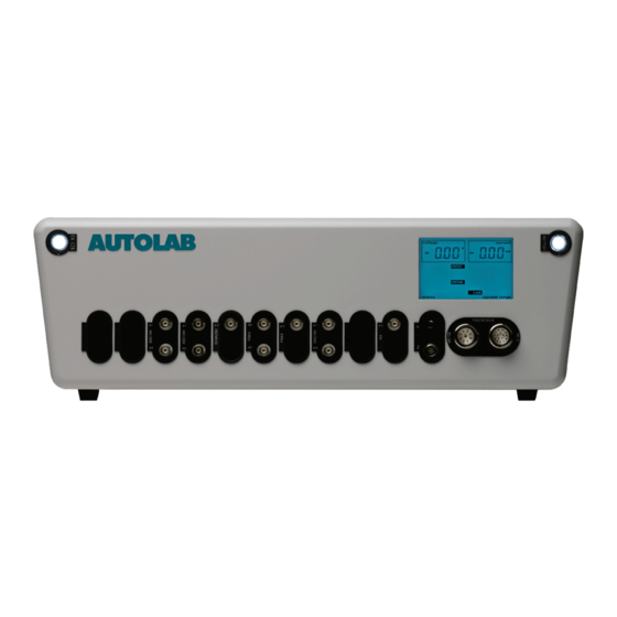
Insert new module for the Autolab 8-Series
INSERT NEW MODULE FOR THE
AUTOLAB 8-SERIES
Editorial
Metrohm Autolab B.V.
Kanaalweg 29 G, 3526 KM Utrecht
The Netherlands
Tel: +31 30 2893154
Fax: +31 30 2880715
E-mail:
autolab@metrohm-autolab.com
Website:
www.metrohm-autolab.com
© Copyright 2011 Metrohm Autolab
1 |
P a g e
Advertisement
Table of Contents


Need help?
Do you have a question about the Autolab 8 Series and is the answer not in the manual?
Questions and answers