Table of Contents
Advertisement
Quick Links
Advertisement
Table of Contents
Troubleshooting

Related Manuals for Metrohm NIRS


Summary of Contents for Metrohm NIRS
- Page 1 NIRS XDS RapidLiquid Analyzer Manual 8.921.8005EN...
- Page 3 Metrohm AG CH-9100 Herisau Switzerland Phone +41 71 353 85 85 Fax +41 71 353 89 01 info@metrohm.com www.metrohm.com NIRS XDS RapidLiquid Analyzer Manual 8.921.8005EN 03.2013 fpe...
- Page 4 Teachware Metrohm AG CH-9100 Herisau teachware@metrohm.com This documentation is protected by copyright. All rights reserved. Although all the information given in this documentation has been checked with great care, errors cannot be entirely excluded. Should you notice any mistakes please send us your comments using the...
- Page 5 Change Control Change Control (initiated with version 1.04): Version Date Summary of Changes September 28, Address changes to reflect move to 7703 Montpelier Road, Laurel, 1.04 2004 MD 20723. Added note about serialized XC-1300 Wavelength Calibration Standard on pages 27, 32 and 34. WST3WCAL is now serialized, and is labeled WST3W105, for example.
-
Page 6: Table Of Contents
Table of contents Introduction ........................6 Site Readiness ........................ 8 Temperature and Humidity ................8 General Environment ..................8 Electrical Power ................... 8 Vibration ...................... 8 Instrument Communication ................8 Instrument Dimensions and Weight ............. 9 XDS Instrument Connection ..................10 Network Connection, connected to an active network port as shown .. - Page 7 Installation and Operating Qualification Documents ..........74 9.2.2 Vision Certificate of Validation ................74 9.2.3 21 CFR Part 11 Compliance ................... 75 Safety and Electrical Certification ............... 77 Troubleshooting ..................78 Lifting and transporting the Metrohm instrument ........82 Index ......................83 ▪▪▪▪▪▪▪...
-
Page 8: Introduction
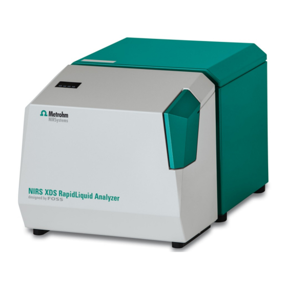
The Metrohm NIRSystems 6500-Series Liquid Analyzer was a versatile, proven design for NIR sampling for many years. The XDS™ Rapid Liquid Analyzer benefits from the improvements in wavelength accuracy, precision, low noise, speed, and overall performance. - Page 9 Lamp changes are performed through a single panel on the rear surface of the instrument. The lamp is easy to remove and replace, and requires no special tools or expertise. The Metrohm Rapid Liquid Analyzer is available with a variety of quartz cuvettes to make analysis straightforward and easy.
-
Page 10: Site Readiness
2 Site Readiness Like most precision instruments, the Rapid Liquid Analyzer is sensitive to environmental conditions that can affect its performance and useful life. Observe the following guidelines when selecting a site and installing the instrument: 2.1 Temperature and Humidity The XDS Analyzer is designed to work in ambient air temperatures from 40-95°F (4.5-35°C). -
Page 11: Instrument Dimensions And Weight
Alternatively, the XDS Rapid Liquid Analyzer can communicate directly with the computer by use of a UTP Crossover Cable, such as CDW #243786, supplied with unit. (gray cable) The computer that operates the instrument must have clear access through the network, and be configured to communicate properly. -
Page 12: Xds Instrument Connection
For computers using Windows 95, 98, or NT 4.0, we recommend upgrade of the computer and operating system to current specifications. CAUTION: Metrohm NIRSystems does not recommend the use of two network cards under any circumstances. Do not use Direct Connection to the instrument along with a network connection to the company network. -
Page 13: Direct Connection, In A Free-Standing Manner With No Network Connection
This method of hookup should not be used when the computer is also connected to a network. Such connection may result in lost commands, lost data, and unsatisfactory software operation. Metrohm cannot be responsible for software and instrument problems resulting from the use of two network cards in the host computer. -
Page 14: Flowchart Diagram Of Xds Communication Protocol
3. Upon being powered up on a LAN, the XDS instrument requests a “dynamic” IP address from the DHCP server which controls the LAN. This IP address is normally granted promptly (typically in 5-10 seconds) so the instrument can function on the LAN. Most DHCP servers track the XDS instrument by the “MAC”... -
Page 15: Network Evolution Issues
3.4.1 Network Evolution Issues This document is as correct as possible at the time or writing. However, network management is an evolving discipline, and conditions will change. Some of the drivers for change include network security, authentication, and data integrity. Technology changes factor into all of these issues. Because the network communication environment is complex and ever-changing, we have tried to provide the basic information needed for connection of the XDS instrument. -
Page 16: Connection In Vision
takes the form “255.255.255.0” or something similar. This scheme is becoming obsolete, as new network management methods are being implemented. TCP/IP: (Transmission Control Protocol/Internet Protocol) is the basic communication language or protocol of the Internet. 3.5 Connection in Vision 1. Log into Vision with your User ID and Password. Click on Configure, Input as shown. -
Page 17: Troubleshooting Connection Problems
3. When Vision “finds” the instrument on the LAN, it will be shown. The dynamic IP address (assigned by the server) is shown, along with the XDS Serial number. The instrument is shown as “Available” on port 2083. Highlight the instrument and click “OK”. -
Page 18: Network Troubleshooting Overview
2. Vision still sees no instrument(s) after expanding the field. This indicates connection or network issues. Verify Cable Type: Verify correct cable type for hookup. Most networks use “patch” cables. Free-standing systems use a “crossover cable”. Power down the XDS instrument, then power it back up. Wait 120 seconds for the XDS instrument to fully reset its communication. - Page 19 Verify these settings: • Obtain an IP address automatically • Obtain DNS server address automatically When finished, click “OK”. Close all other boxes opened for this verification. If the settings were not set properly, it may be necessary to exit Windows XP, then re- enter XP, to have the correct settings take effect.
- Page 20 Network Solution 2: Returning to the Local Area Connection Status dialog box, note these items for the computer: • Address Type: (should be “assigned by DHCP”) • IP Address: Write this address down for the next step • Subnet Mask: Write this down for the next step If connection cannot be achieved, it...
- Page 21 Network Solution 4: Verify that the Firewall on the computer has Vision loaded as an “exception”. This is located under “Control Panel”, “Windows Firewall”. If this is not enabled, click “Add Program” and select “Vision” from the list. When finished, click “OK” Network Retry, XP and Vista: Windows XP and Vista users...
-
Page 22: Direct Connection Troubleshooting Overview
3.6.2 Direct Connection Troubleshooting Overview If no XDS instrument shows as “available”, the computer may need to be configured for the IP address range of the XDS instrument. It may be necessary to contact your IT department for assistance with these issues. First, verify the following: •... -
Page 23: Assembly Of The Instrument
The XDS Rapid Liquid Analyzer will be assembled and installed by a trained representative of Metrohm. This person will perform a full suite of diagnostics to verify correct operation, and will explain basic operating points. Assembly information is given as a guide for the user, should re- assembly ever be required due to an instrument move or for other reasons. - Page 24 1. Load Vision Spectral Analysis Software onto the computer designated to operate the XDS instrument. 2. Place the monochromator on the lab bench in the position shown. 3. Open the right-hand panel of the instrument. Pull it gently by a fin, until the catch releases.
- Page 25 5. Insert the AC power cable into the AC power block as shown. 6. Attach the RJ-45 cable to the network connector on the instrument. If using Direct Connection, use the gray cable from the instrument accessory kit. If using network connection, do not use the gray cable, as it is a “UTP crossover”...
- Page 26 9. Lift the release handle on the monochromator and engage the module “catches” to the locking togs on the monochromator. (Module not shown to allow a good view of handle.) Push monochromator and module together firmly (with handle up) then lower the release handle.
- Page 27 13. When all the above assembly is finished, turn on the power switch on the monochromator. It is located on the lower surface, on the right-hand side as shown. The monochromator performs some initialization tests, which take a moment. Some noises will be heard as items find their initial positions.
-
Page 28: Rapid Liquid Module
5 Rapid Liquid Module The XDS™ Rapid Liquid Analyzer is designed for sampling of many types of customer samples. This section describes initial calibration steps, which are detailed in section 7.1. This section gives a functional overview, so the operation can be anticipated and understood. 5.1 Wavelength Calibration of the Rapid Liquid Analyzer The Rapid Liquid Analyzer uses an innovative method of wavelength calibration, to assure consistency between like... -
Page 29: Cuvette Types
5.4 Flow-Through Fittings Metrohm has provided flow-through bulkhead fittings on the door of the XDS Rapid Liquid Module for users who require analysis of flowing liquids. These ports may be attached, using flexible tubing, to a suitable cuvette or cell which fits into the sample drawer. -
Page 30: Cuvette Lifting Handle
To access the outer fittings, gently lift the black cover and peel it back. The ports are exposed as shown. Save the cover as a light- block, in the event the ports are not used in later work. It should be re-installed to prevent light seepage through the fittings. -
Page 31: Instructions For Closing The Sample Drawer Using Vision
• If scanning at an elevated temperature using the controller, be sure samples are not already above that temperature from prior processing, water baths, or for any other reason. If in doubt about temperature consistency, check samples using a calibrated temperature device to determine that sample temperature is well-controlled. - Page 32 Many factors may come into consideration, including mixing accuracy, lab error for samples analyzed by other methods, and operator differences. Contact your Metrohm NIRSystems Product Specialist for more information. ▪▪▪▪▪▪▪...
-
Page 33: Vision Software: Connection To The Instrument
Once installed, click on the Vision icon on the desktop. The log-in box appears on the opening screen. Enter the default User ID, “NIRS”. It is not case-sensitive. Tab (or mouse) to the Password box, and enter the default password, “NIRS”. - Page 34 Vision asks if the default directory location is acceptable. Click on “Yes”. Vision creates a directory for the project as shown. Vision prompts the user to connect to the instrument. Be sure the instrument is turned on and is ready. Click on “Acquire New Data”.
- Page 35 described in section 7.1.3 of this manual. If so, this option must be set in Project Options. To do so, cancel out of Data Acquisition, and follow the steps on the next page. If you do not wish to use Blank Correction, continue with the Data Collection Method (DCM) selection.
- Page 36 The default time is 0 seconds, as shown here. Use 32 scans for “Sample” and 32 scans for “Reference.” The instrument scans on each forward swing and each backward swing of the grating, unlike previous Metrohm instruments. Thus, 32 scans ▪▪▪▪▪▪▪...
- Page 37 are accomplished on only 16 grating cycles, and are very rapid. Click “OK” when finished. The user may check test parameters, Click the “Test Param” button, then select the wavelength area of interest. Specifications will be displayed. The user will hear a slight ticking sound from the internal order sorter whenever the lamp is on. This is normal, and has no effect on component life.
-
Page 38: Instrument Diagnostics
7 Instrument Diagnostics Vision provides diagnostics for instrument setup, which must be performed before use of the instrument for analysis. Following these diagnostics, another set of diagnostics is provided to evaluate the ongoing performance of the instrument. These are explained in the sections that follow. Vision provides diagnostics for instrument setup, which must be performed before use of the instrument for analysis. -
Page 39: Instrument Identification
Use Instrument Calibration (XDS only) This is a method to adjust the instrument wavelength profile to an external, traceable wavelength standard. It is checked as a default for XDS. Required for Calibration Transfer. Use Window Correction (XDS only) This is only used with specific XDS process Instruments. Do not select this option. When calibration or library transfer (between instruments) is anticipated, be sure that Blank Correction and Instrument Calibration are selected. - Page 40 Wavelength Linearization uses an internal wavelength standard set to determine a set of internal, arbitrary peak positions that the instrument will use to maintain repeatability of wavelength response. The NIR wavelength positions of these peaks appear as shown. The scale of this display is marked in encoder pulses, which do not relate to nanometers directly.
-
Page 41: Blank Correction
The results screen shown above is typical. Peak positions for the reference materials are located using a peak-finding algorithm. These “found” peaks are compared to the nominals. Differences should be no more than 0.4nm for any peak. Click “Yes” to send the linearization to the instrument. This is done twice, once for each direction of grating motion. -
Page 42: Instrument Calibration
The menu selection for Blank Correction is available when the option is selection in This Project’s Options, and the Data Collection Method (DCM) has the Blank Correction box is checked. This is explained in section 7.1.2. Upon selection of Blank Correction from the Diagnostics menu, Vision takes an instrument reference. - Page 43 It was later determined that better transferability between instruments could be achieved if each standard was calibrated on the Metrohm NIRSystems master transmission instrument. Since that time, each WST3Wxxx standard is serialized, with a matching calibration file. For example, the standard may now be labeled “WST3W068”.
- Page 44 Instrument Calibration on the spectrum is virtually beyond measurement using normal instrument techniques, yet has such a positive effect on transferability that Metrohm NIRSystems recommends it always be used with XDS instruments. It is set as a default with XDS instruments in Configure, Options.
- Page 45 Vision takes an instrument reference, which takes about 20 seconds. This dialog box is displayed. Next a sample scan is taken, and this box is displayed. This takes about 30 seconds. Wavelength Linearization is performed in two sections, each of which takes about 45 seconds. The user must confirm the linearization to proceed.
- Page 46 Following Wavelength Linearization, the user is asked to select a standard file. This is provided on the mini- CD found in the standards box, and may be read through the A: drive. The file may be copied onto the computer in the C:\Vision directory, for convenience.
-
Page 47: Ipv Setup (Instrument Performance Verification)
These will be measured later in Wavelength Certification, as a test of how well the instrument is maintaining the settings established in Instrument Calibration. 7.1.5 IPV Setup (Instrument Performance Verification) IPV Setup is provided as a method to record initial instrument response to calibrated photometric transmission standards. - Page 48 Vision requests a “Standard File”. This is provided on a mini-CD, packed in the wooden box with the standards. Insert this diskette into the A: drive, select that drive in the dialog box, and click on the TSS3xxxx.da file as shown. (The serial number will be different, of course.) Click “Open”.
-
Page 49: Evaluation Diagnostics
7.2 Evaluation Diagnostics Evaluation Diagnostics are used to verify that the instrument is operating within allowable parameters. These tests should be run approximately once per week. This information is meant to guide the user through the tests in an expeditious manner. A more complete description of these tests is given in the Vision Manual, in the Diagnostics section. - Page 50 When instructed, insert the WST3xxxx standard into the sample drawer. The label should face the user when inserting the standard. Place the standard into the drawer. The serial number should be readable from the front, as shown. Click “OK” when ready. After the test is complete, a spectrum of the standard is shown in the upper right quadrant of the screen.
- Page 51 page titled “Instrument Calibration Verification”. These peaks are used to set the “Instrument Wavelength Profile,” and one peak is used for bandwidth calculation. The wavelengths used for the instrument wavelength profile are well-defined, stable peaks in the wavelength standard. These are the same peaks used during Instrument Calibration. Wavelength Certification is a verification that the peaks are in correct positions, and that the peak positions are consistent over time.
-
Page 52: Performance Test
for future recall. See the Vision manual for a full explanation. If the instrument passes the NIST-type peaks (page 1 of the report), but fails on the FOSS-defined peaks, Vision will recommend that the user run Instrument Calibration to set the wavelengths properly. - Page 53 At the end of Performance Test, all measured values are compared with acceptance criteria stored in Vision. If all results meet acceptance criteria, the test is successful and this dialog box is displayed. Before clicking “Close All Reports”, the user is directed to the tabular display.
-
Page 54: Photometric Test
Noise Summary displayed using the OpQual tab. The OpQual tab brings up the display shown. This shows results of the Noise Test for each of the four wavelength regions. These regions are: • 400-700nm • 700-1100nm • 1100-1700nm • 1700-2500nm For each region, results are given for •... - Page 55 Photometric Test provides a method to verify ongoing photometric performance of the instrument. This is a requirement for pharmaceutical users. Test results are stored in the Diagnostic Database, and may be accessed at any time. Control charts are plotted (after several tests have been stored) to provide an ongoing record of performance.
- Page 56 Vision requests a tolerance file. The tolerance file was loaded in the C:\Vision directory, and is an “XDA” formatted file. Select this file and click “Open”. Current versions of Vision include a newer version of this tolerance file, which may be named “IPVXDS02, 03, or higher.
- Page 57 Select the requested standard from the set. Labels on the top of each standard identify the number of the standard. Approximate transmission values are as follows: • 0.25 AU (Absorbance Units) • 0.50 AU • 1.0 AU • 2.0 AU •...
-
Page 58: Gain Test
After each standard is run, Vision plots the comparison for each wavelength area as shown. Tolerances are automatically applied, and a “Pass” or “Fail” indication is given. Continue to follow the on-screen prompts for each standard. Vision requests the T02, T03, T04, and T05 standards. -
Page 59: Low Flux Test
NIR and Visible regions. Gain Factor is a measure of signal amplification. In the NIR region (1100-2500nm) it occurs in steps of 1, 2, 4, 10, 20, 40 and 80. In the Visible region (400-1100nm) the gains range from 1 to 80,000. Gain Adjust can be helpful when troubleshooting an instrument. - Page 60 XC-1310 Transmission Standard Set contains a 10% transmission standard (T033xxxx) which may be used for this test, if desired. The T03 transmission standard may be positioned in the sample drawer. Vision closes the drawer to run the Low Flux Test when using an external sample (standard).
-
Page 61: Temperature Control Setup
specifications. Vision reports a pass or fail based upon successful test completion. Results are stored in the Diagnostic Database for later recall. The user may print results, or click “Close” to complete the test. 7.3 Temperature Control Setup The XDS Rapid Liquid Analyzer uses a commercial temperature controller to maintain analysis temperature in the sample drawer. - Page 62 samples up to the set point temperature. This is located in the Data Collection Method (DCM) as shown in the next illustration. The Equilibration Time is measured in seconds. If the Equilibration Time is set for 30 seconds, the instrument will commence a sample scan 30 seconds after the operator clicks on the “Sample” icon. The Equilibration Time should be long enough for every sample to reach the desired temperature.
-
Page 63: Instrument Maintenance
This is a diagram of a top view of the inside of the instrument, showing the relative location of major components. Do not attempt to open the instrument enclosure unless directed to do so by trained Metrohm service personnel. The instrument should be kept clean at all times. If it becomes dusty or dirty, wipe it with a damp, soft cloth to restore the finish. - Page 64 Open the door of the filter compartment. Grasp the upper fin as shown and gently pull. The snaps should release, allowing the door to open as shown. Lower the door as shown to expose the filter material. Using a 1/4” nut driver, remove the four #4-40 nuts that hold the filter frame in place.
-
Page 65: Lamp Replacement
The screws should penetrate the filter material fully. Install the filter frame. Install the #4-40 nuts and tighten (hand-tight) as shown. Gently close the instrument door. Order new filter material from your Metrohm authorized distributor immediately. 8.3 Lamp Replacement ▪▪▪▪▪▪▪... - Page 66 The lamp may need to be changed after several thousand hours of use. Generally the instrument will exhibit high noise during Performance Test, or when wavelength precision (repeatability) has begun to rise from established values. Follow this procedure: 1. Turn off Instrument power and unplug AC power cord from AC receptacle or supply.
- Page 67 4. Grasp the lamp retaining ring as shown. Push inward slightly, and rotate clockwise (the top to the right; the bottom to the left) to release the retaining ring from the shoulder screws. 5. This photo shows the lamp retaining ring in the removal position.
- Page 68 Discard this lamp immediately. Order a new lamp from your Metrohm distributor to keep for the next lamp change. Always keep a spare lamp in stock, to avoid last-minute emergencies. The part number is XA-3000.
- Page 69 10. Place the lamp retaining ring over the shoulder screws, and rotate counter- clockwise (top side to left, bottom to right) to lock the lamp retaining ring into place. This photo shows the ring being rotated into position. 11. When the lamp is properly locked, the assembly will appear as shown.
-
Page 70: Fuse Replacement
Always keep a spare lamp in stock, to avoid last-minute emergencies. If you do not have a spare lamp after changing this lamp, order one from your Metrohm distributor immediately. NOTE: The lamp is a very special assembly, and should never be replaced with any substitutes. - Page 71 Turn off power and unplug the instrument from AC power. Open the side cover. Remove the AC power plug from the AC power block of the instrument. Use a tool (such as an Allen wrench) to pull the housing open. There is a small slot where the tool can be inserted to pry the door gently open.
-
Page 72: Maintenance Log
Remove old fuses from holder and discard. Install the new fuses as shown. Fuse Ratings: • 5A 250 VAC, 5 x 20mm • Slo-Blo • (2) Required They clip in to the plastic holder, and should be positioned at the center of the holder. Close the fuse door fully. - Page 73 Maintenance Log tracks all instrument tests, as shown in the screen below. In addition, the user may enter text comments, which are saved as part of the log. Enter the text, then click on OK. This screen shows entries, sorted by record number. To re-sort by another parameter, click on the column heading.
-
Page 74: Validation Tools
User Application (Customer samples, limits detection, range of calibration set, calibration precision, and other factors.) Users have requested specific tools and techniques to achieve validation. Metrohm has provided the following tools to assist and expedite the task. Each item is described. -
Page 75: Installation And Operating Qualification Documents
(IPC) is offered to meet these requirements. It is performed every six (6) months, on site, by a certified technician. Some key program features: • Measures instrument response using standards calibrated to Metrohm Master Instrument Assures consistent response between instruments of identical design. •... -
Page 76: Metrohm Master Instrument Program
(yet complementary) techniques to assure consistency and accurate response. Full records of testing and calibration are logged and maintained on an ongoing basis. By maintaining a Master Instrument, Metrohm is able to track long-term response of field instruments, verify ongoing operational improvements to manufactured systems, and provide yearly re-calibration of NIRStandards used in Instrument Performance Certification. -
Page 77: Cfr Part 11 Compliance
At several thousand pages, this CD will satisfy your Internal Audit Staff and external regulators that Vision Software was designed from the first moment to be a fully code-validated, tested product for use in the pharmaceutical industry. Documents were selected (from the enormous quantity of records in our logs) based upon the patterns set during the many customer audits of our software development process. - Page 78 This screen shows many of the setup items to be set by the System Manager for 21 CFR Part 11 Compliance. To access this screen, click on Configure, Account Policy. A 21 CFR Verification Document is available for users who wish to verify key features.
-
Page 79: Safety And Electrical Certification
In the unlikely event of problems, contact Metrohm service or your next local authorized Distributor. This equipment is to be used only for the purpose specified. If used for any other purpose, the protection provided by the equipment may be impaired. -
Page 80: Troubleshooting
Recommendations are listed in logical order of occurrence wherever possible. When all recommendations have been checked, and if the instrument is not operating, please contact Metrohm Service Department (or your local authorized distributor) if the problem is not solved. - Page 81 1. Verify that the sample drawer is not jammed or impeded in any way. It should be free to open and Instrument fails Wavelength close under software control. Linearization 2. Instrumental problems – contact Metrohm service or your authorized distributor. ▪▪▪▪▪▪▪...
- Page 82 1. Verify that the sample drawer is not jammed or impeded in any way. It should be free to open and close under software control. 2. Temperature and/or humidity may be changing rapidly during the test. This can usually be observed as large spectral activity between 1300- 1400nm and 1800-1900nm.
- Page 83 To check fan operation, cycle the Power Switch. Note if the fans come on for a short burst, approximately 25 seconds after power, the fans are operating properly. If these measures do not correct the problem, please contact Metrohm service or your next local distributor. ▪▪▪▪▪▪▪...
-
Page 84: Lifting And Transporting The Metrohm Instrument
12 Lifting and transporting the Metrohm instrument Always separate the module from the monochromator (shown) before lifting or transporting the instrument. When the module is attached, raise this handle to separate the module from the monochromator. Slide the module away from the monochromator. -
Page 85: Index
13 Index Accessory Kit ..........21 Low Flux Test ........57, 58 Assembly............. 21 Maintenance ........61, 70, 71 Bias ............. 52 Module ......9, 21, 24, 26, 27, 37 Monochromator ........9, 21 CFR 21 ........7, 31, 72, 73, 74 Network Connection ........
Need help?
Do you have a question about the NIRS and is the answer not in the manual?
Questions and answers