
Subscribe to Our Youtube Channel
Related Manuals for Metrohm OptiProbe NIRS XDS


Summary of Contents for Metrohm OptiProbe NIRS XDS
- Page 1 NIRS XDS Transmission Analyzer Transmission OptiProbe Manual 8.921.8007EN / 2015-09-07...
- Page 3 Metrohm AG CH-9100 Herisau Switzerland Phone +41 71 353 85 85 Fax +41 71 353 89 01 info@metrohm.com www.metrohm.com NIRS XDS Transmission Analyzer Transmission OptiProbe Manual 8.921.8007EN / 2015-09-07 fpe/ahag...
- Page 4 Technische Dokumentation Metrohm AG CH-9100 Herisau techdoc@metrohm.com This documentation is protected by copyright. All rights reserved. This document has been prepared with great care. However, errors can never be entirely ruled out. Please send comments regarding possible errors to the address above.
-
Page 5: Table Of Contents
■■■■■■■■■■■■■■■■■■■■■■ Table of contents Table of contents 1 Introduction Instrument description ............1 Intended use ................. 2 About the documentation ........... 2 1.3.1 Symbols and conventions ............2 Safety instructions ..............3 1.4.1 General notes on safety ............3 1.4.2 Electrical safety ................ - Page 6 Replacing the fan filter ............17 5.2.3 Replacing the lamp ..............20 5.2.4 Replacing the fuse ..............28 Quality management and qualification with Metrohm . . 30 6 Appendix Accessories for measuring probes ........32 6.1.1 Transmission probe pair ............32 6.1.2...
- Page 7 ■■■■■■■■■■■■■■■■■■■■■■ Table of figures Table of figures Figure 1 Front - measuring instrument ............5 Figure 2 Rear - monochromator ..............6 Figure 3 Status display ..................6 Figure 4 Instrument connection ..............7 Figure 5 On/off switch .................. 13 Figure 6 NIRS Vial Heater ................
-
Page 9: Introduction
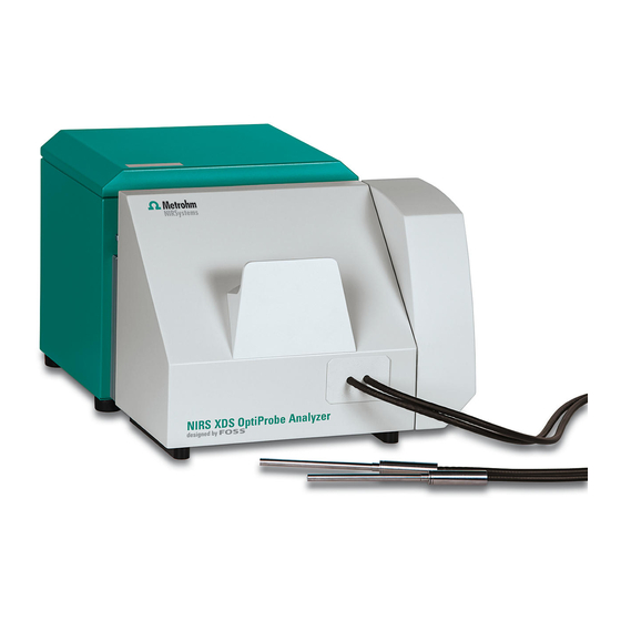
NOTE You can request application descriptions in the form of Application Notes and Application Bulletins from your Metrohm representative or download them from http://www.metrohm.com. Instrument description The NIRS XDS Transmission Analyzer is a measuring instrument for trans- mission measurement in the visible to near-infrared wavelength range. -
Page 10: Intended Use
■■■■■■■■■■■■■■■■■■■■■■ 1.2 Intended use Intended use The NIRS XDS Transmission Analyzer is designed for use in production facilities. It can be used for incoming goods inspection or for production process monitoring. This instrument is suitable for measuring chemicals and flammable sam- ples. -
Page 11: Safety Instructions
1.4.2 Electrical safety The electrical safety when working with the instrument is ensured as part of the international standard IEC 61010. WARNING Only personnel qualified by Metrohm are authorized to carry out service work on electronic components. ■■■■■■■■... -
Page 12: Flammable Solvents And Chemicals
■■■■■■■■■■■■■■■■■■■■■■ 1.4 Safety instructions WARNING Never open the housing of the instrument. The instrument could be damaged by this. There is also a risk of serious injury if live components are touched. There are no parts inside the housing which can be serviced or replaced by the user. -
Page 13: Overview Of The Instrument
■■■■■■■■■■■■■■■■■■■■■■ 2 Overview of the instrument 2 Overview of the instrument Figure 1 Front - measuring instrument Status display Monochromator Measuring module Transmission probe receiver Transmission probe sender ■■■■■■■■... -
Page 14: Monochromator
■■■■■■■■■■■■■■■■■■■■■■ 2.1 Monochromator Monochromator 2.1.1 Connectors/rear Figure 2 Rear - monochromator On/off switch Fuse holder Power socket Covering Network connection socket 2.1.2 Status display Figure 3 Status display Instrument on Measurement ongoing Connected to network Lamp on Monochromator connected to measur- ing module ■■■■■■■■... -
Page 15: Instrument Connection
■■■■■■■■■■■■■■■■■■■■■■ 2 Overview of the instrument 2.1.3 Instrument connection The two modules are connected via mechanical, optical and electrical interfaces, combining monochromator and measuring module to one measuring instrument. Figure 4 Instrument connection Locking lever Optical interface Mechanical interface Electrical interface ■■■■■■■■... -
Page 16: Installation
■■■■■■■■■■■■■■■■■■■■■■ 3.1 Unpacking and inspecting the instrument 3 Installation Unpacking and inspecting the instrument 3.1.1 Packaging The instrument is supplied in highly protective special packaging together with the separately packed accessories. Keep this packaging, as only this ensures safe transportation of the instrument. 3.1.2 Checks Immediately after receipt, check whether the shipment has arrived com-... -
Page 17: Handling Fiber
■■■■■■■■■■■■■■■■■■■■■■ 3 Installation NOTE Dimensions and weights The dimensions and weights are listed in the technical specifications (see Chapter 7.8, page 38). 3.2.2 Handling fiber CAUTION Damage to the fiber Rough and incorrect handling can damage the fibre so that it cannot be used for further measurements. -
Page 18: General Conditions
■■■■■■■■■■■■■■■■■■■■■■ 3.3 Connecting monochromator to measuring module 3.2.4 General conditions Dust and dirt may compromise the instrument's cooling and should there- fore be prevented as far as possible. The maintenance procedures for the fan filter are described as follows (see Chapter 5.2.2, page 17). - Page 19 ■■■■■■■■■■■■■■■■■■■■■■ 3 Installation 2 Positioning measuring module and pushing together Align the measuring module with the monochromator and push ■ together. 3 Locking monochromator and measuring module Push the locking lever down to connect the two instrument parts. ■ ■■■■■■■■...
-
Page 20: Connecting The Power Supply Cable
■■■■■■■■■■■■■■■■■■■■■■ 3.4 Connecting the power supply cable Connecting the power supply cable The NIRS XDS Transmission Analyzer instrument contains a permanently installed power supply unit and can be directly connected to the power supply with a power supply cable. The power supply unit automatically supports operating voltages between 100 and 240 VAC at 50 / 60 Hz. -
Page 21: Switching On The Instrument
■■■■■■■■■■■■■■■■■■■■■■ 3 Installation NOTE Direct connection to computer When directly connecting the measuring instrument to a computer, no other network card for connection to a local network may be installed at the same time. This leads to communication errors and disruptions. In network operation, connect the measuring instrument via the net- ■... -
Page 22: Setting Up Accessories
■■■■■■■■■■■■■■■■■■■■■■ 3.8 Setting up accessories Setting up accessories Metrohm offers a wide range of accessories for the NIRS XDS Transmis- sion Analyzer instrument. A detailed description of how to use the accessories can be found in the appendix (see Chapter 6, page 31). -
Page 23: Operation
■■■■■■■■■■■■■■■■■■■■■■ 4 Operation 4 Operation Apart from the main switch for switching on and off, the NIRS XDS Trans- mission Analyzer instrument does not have any other controls. The complete instrument configuration, calibration and measurement is set up and operated via the control software. ■■■■■■■■... -
Page 24: Operation And Maintenance
Maintenance of the NIRS XDS Transmission Analyzer instrument is best carried out as part of annual service, which is performed by specialist per- sonnel from Metrohm. A shorter maintenance interval may be necessary if you frequently work with caustic and corrosive chemicals. -
Page 25: Overview
■■■■■■■■■■■■■■■■■■■■■■ 5 Operation and maintenance NOTE Do not attempt to open the optical housing of the monochromator. There are no parts inside the housing which can be serviced by the user. Damages resulting from opening the instrument are not covered by the warranty. - Page 26 ■■■■■■■■■■■■■■■■■■■■■■ 5.2 Maintenance 2 Removing the filter cover Grab the filter cover with both hands and gently take it off start- ■ ing on top. 3 Cleaning/replacing the filter Remove the filter from the cover and examine it. ■ If the filter shows no damage, then it can be cleaned and used ■...
- Page 27 ■■■■■■■■■■■■■■■■■■■■■■ 5 Operation and maintenance Place the cleaned or new filter symmetrically into the filter cover. ■ Make sure the filter material is correctly positioned and is not wrinkled or folded. The edges should form a good seal. 4 Mounting the filter cover Mount the filter cover to the frame starting on the top and push it ■...
-
Page 28: Replacing The Lamp
■■■■■■■■■■■■■■■■■■■■■■ 5.2 Maintenance 5 Connecting the instrument Plug in the network cable. ■ Plug in the power supply cable. ■ Switch on the instrument. ■ 5.2.3 Replacing the lamp Replacing the lamp The lamp must be replaced if it is defective or when its performance is insufficient. - Page 29 Remove the lamp with appropriate care. ■ NOTE Spare part A new spare lamp is available from your Metrohm distributor under the article number 6.7430.000. It is advisable to keep spare lamps in stock. ■ Only original lamps must be used in the instrument.
- Page 30 ■■■■■■■■■■■■■■■■■■■■■■ 5.2 Maintenance 2 Removing the lamp covering Loosen the six knurled screws until they are free. ■ If the screws are too tight, loosen them with a screwdriver. ■ Carefully remove the back panel and put it aside. ■ NOTE The built-in lamp is the only part subject to maintenance work.
- Page 31 ■■■■■■■■■■■■■■■■■■■■■■ 5 Operation and maintenance 3 Loosening the lamp cables The cable clips for connecting the lamp are in the upper right corner of the lamp box. The lamp itself is secured with a quick-opening clamping fixture. On the lamp is a black arrow, which has to be aligned with the milled groove at the top of the mounting area.
- Page 32 ■■■■■■■■■■■■■■■■■■■■■■ 5.2 Maintenance 5 Replacing the lamp CAUTION Damage to the lamp Fingerprints and greasy deposits may damage the lamp. Do not touch the glass part of the lamp or the inner side of the reflector. Remove the lamp from the lamp holder and replace it with a new ■...
- Page 33 ■■■■■■■■■■■■■■■■■■■■■■ 5 Operation and maintenance 6 Inserting the lamp holder Place the lamp into the opening and align the black arrow with ■ the milled groove (on top). Position the lamp holder over the lamp and the locking bolts. ■ Carefully push the lamp holder down, rotate anti-clockwise (to ■...
- Page 34 ■■■■■■■■■■■■■■■■■■■■■■ 5.2 Maintenance 7 Connecting the lamp cables Place the two spade terminals into their according screw terminal ■ and tighten with a screwdriver. NOTE Polarity The polarity is irrelevant. 8 Attaching the lamp covering Position the covering with the screws over the thread bore holes. ■...
- Page 35 ■■■■■■■■■■■■■■■■■■■■■■ 5 Operation and maintenance 9 Connecting the instrument Plug in the network cable. ■ Plug in the power supply cable. ■ Switch on the instrument. ■ 10 Connecting the instrument to the control software Start the control software and connect to the instrument. ■...
-
Page 36: Replacing The Fuse
■■■■■■■■■■■■■■■■■■■■■■ 5.2 Maintenance NOTE Stabilizing time The instrument features a monitoring function for stabilizing which can be deactivated in the control software. If the monitoring is deactivated, the instrument takes about 20 to 30 minutes for cor- rect stabilizing. 11 Calibrate the instrument The instrument has to be recalibrated every time a lamp is replaced. - Page 37 ■■■■■■■■■■■■■■■■■■■■■■ 5 Operation and maintenance 3 Replacing the fuse Remove the old fuses from the fuse holder and replace with new ■ fuses (see Chapter 7.2, page 35). Insert the fuse holder with the new fuses into the opening until it ■...
-
Page 38: Quality Management And Qualification With Metrohm
Maintenance The electronic and mechanical functional groups of Metrohm instruments can and should be checked by specialist personnel from Metrohm as part of a regular preventive maintenance schedule. Please ask your local Metrohm representative regarding the precise terms and conditions involved in concluding a corresponding maintenance agreement. -
Page 39: Appendix
■■■■■■■■■■■■■■■■■■■■■■ 6 Appendix 6 Appendix CAUTION Sample preparation Spilled sample material can enter the instrument and cause damages. Prepare samples outside of the instrument. ■ Use appropriate sample cups. ■ After filling, the sample cup must be clean on the outside. ■... -
Page 40: Accessories For Measuring Probes
■■■■■■■■■■■■■■■■■■■■■■ 6.1 Accessories for measuring probes Accessories for measuring probes 6.1.1 Transmission probe pair The transmission probe pair allows the measurement of liquid samples. Calibrating the transmission probe pair The calibration is carried out with a calibration fixture that takes up the calibration standard and fixates the transmission probe pair. -
Page 41: Nirs Vial Heater
■■■■■■■■■■■■■■■■■■■■■■ 6 Appendix 3 Placing the covering Place the covering over the calibration standard. ■ 4 Calibration / Carrying out the test The procedure with the necessary information is described in the ■ tutorial for the control software. 6.1.2 NIRS Vial Heater The NIRS Vial Heater is operated in combination with the NIRS XDS Transmission OptiProbe Analyzer. -
Page 42: Calibration Standards
■■■■■■■■■■■■■■■■■■■■■■ 6.2 Calibration standards Figure 6 NIRS Vial Heater NOTE The handling of the NIRS Vial Heater is described in the 8.921.8009EN manual. Calibration standards NOTE Choosing the calibration standard The necessary calibration standards for the calibration of the measuring instrument are listed in the tutorial for the control software under the respective measuring modules. -
Page 43: Technical Specifications
■■■■■■■■■■■■■■■■■■■■■■ 7 Technical specifications 7 Technical specifications LAN interface RJ-45 Ethernet connection socket for the data transfer to the PC with the control software via direct connection or via the network. Power connection Nominal voltage 100 - 120 V and 220 - 240 V (±10%, autosensing) range Frequency 50 and 60 Hz (autosensing) -
Page 44: Operation
■■■■■■■■■■■■■■■■■■■■■■ 7.4 Operation Operation Measuring mode Transmission Wavelength range 400 - 2,500 nm Detectors Silicon (400 - 1,100 nm), Lead sulfide (1,100 - 2,500 nm) Optical bandwidth 8.75 nm (±0.10 nm) Spectral data 0.5 nm interval Number of data 4,200 points per spec- trum Scan rate... -
Page 45: Safety Specifications
■■■■■■■■■■■■■■■■■■■■■■ 7 Technical specifications Safety specifications This instrument fulfills the following electrical safety requirements: CE marking in accordance with the EU directives: 2006/95/EC (Low Voltage Directive, LVD) ■ 2004/108/EC (EMC Directive, EMC) ■ Design and testing According to EN/IEC/UL 61010-1, CSA-C22.2 No. 61010-1, protection class I, EN/IEC 60529, degree of protection IP52. -
Page 46: Dimensions/Material
■■■■■■■■■■■■■■■■■■■■■■ 7.8 Dimensions/material Dimensions/material Monochromator Dimensions Width 380 mm Height 348 mm Depth 335 mm 21.0 kg Weight Material Housing Steel sheet NIRS XDS Transmission Analyzer module Dimensions 457 mm Width Height 381 mm Depth 275 mm Weight 9.0 kg Material Housing Aluminum... -
Page 47: Accessories
Internet. You can download this information using the article number as follows: Downloading the accessories list 1 Type http://partslists.metrohm.com into your Internet browser. The Partslists webpage will be displayed. 2 Select the desired output language. -
Page 48: Glossary
■■■■■■■■■■■■■■■■■■■■■■ Glossary Absorbance Units; unit of the (actually dimensionless) absorbance. Data interval Distance of nearby data points on the wavelength axis; depends on the angle between nearby grid positions. Not to be confused with the optical bandwidth; the spectral data interval does not show the optical resolution of the spectrometer. - Page 49 ■■■■■■■■■■■■■■■■■■■■■■ Glossary Wavelength precision Variance of the measured wavelength at repeated measurements with a single instrument or a group of instruments. ■■■■■■■■...
-
Page 50: Index
Power supply unit ..... 12 Accessories Measuring probe ...... 32 Set up ........ 14 Transmission probe pair ..32 Quality management ....30 Metrohm Service ...... 16 Installation qualification .... 30 Instrument Safety instructions ...... 3 Operational qualification ..30 Switch on ......13 Service ........
Need help?
Do you have a question about the OptiProbe NIRS XDS and is the answer not in the manual?
Questions and answers