Table of Contents
Advertisement
Quick Links
Advertisement
Table of Contents

Subscribe to Our Youtube Channel
Related Manuals for Metrohm DS2500


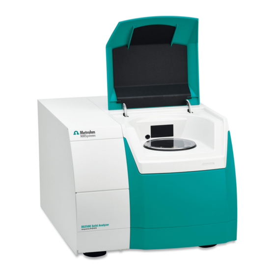
Summary of Contents for Metrohm DS2500
- Page 1 DS2500 Liquid Analyzer Manual 8.0929.8001EN / 2021-04-30...
- Page 3 Metrohm AG CH-9100 Herisau Switzerland Phone +41 71 353 85 85 Fax +41 71 353 89 01 info@metrohm.com www.metrohm.com DS2500 Liquid Analyzer Manual 8.0929.8001EN / 2021-04-30...
- Page 4 Technical Communication Metrohm AG CH-9100 Herisau techcom@metrohm.com This documentation is protected by copyright. All rights reserved. This documentation has been prepared with great care. However, errors can never be entirely ruled out. Please send comments regarding possible errors to the address above.
-
Page 5: Table Of Contents
Calibrating the instrument ............. 12 3.8.2 Analyzing liquid samples ............14 4 Operation 5 Maintenance Maintenance by Metrohm Service ........20 Maintenance by the user ........... 20 5.2.1 Cleaning the instrument ............21 5.2.2 Cleaning the sample holder ........... 22 5.2.3... - Page 6 Table of contents ■■■■■■■■■■■■■■■■■■■■■■ 5.2.4 Replacing the lamp ..............23 5.2.5 Replacing the fan filter ............32 5.2.6 Replacing a fuse ..............35 6 Technical specifications Interfaces ................38 Power connection ............... 38 Ambient conditions ............38 Dimensions ................38 Housing ................
- Page 7 Front DS2500 Liquid Analyzer ............6 Figure 2 Rear DS2500 Liquid Analyzer ............. 7 Figure 3 DS2500 Liquid Analyzer sample holders ..........8 Figure 4 Place the disposable vial in the sample compartment....... 15 Figure 5 Disassembling the sample holder ............. 22...
-
Page 9: Introduction
The DS2500 Liquid Analyzer can be actively cooled so that there is no delay between measurements at various temperatures. The DS2500 Liquid Analyzer is designed for quality monitoring of the pro- duction processes. Use the DS2500 Liquid Analyzer for the following pur- poses: Quick and non-destructive incoming goods inspection of liquids ■... -
Page 10: Intended Use
1.2 Intended use ■■■■■■■■■■■■■■■■■■■■■■ The DS2500 Liquid Analyzer is operated with the control software via an external computer. Intended use The DS2500 Liquid Analyzer is designed for use in production facilities. The DS2500 Liquid Analyzer can be used for incoming goods inspection or atline or offline for production process monitoring. -
Page 11: Safety Instructions
■■■■■■■■■■■■■■■■■■■■■■ 1 Introduction Instruction step Carry out these steps in the sequence shown. Method Dialog text, parameter in the software File ▶ New Menu or menu item [Next] Button or key WARNING This symbol draws attention to a possible life-threat- ening hazard or risk of injury. -
Page 12: Electrical Safety
The electrical safety when working with the instrument is ensured as part of the international standard IEC 61010. WARNING Only personnel qualified by Metrohm are authorized to carry out service work on electronic components. WARNING Never open the housing of the instrument. The instrument could be damaged by this. -
Page 13: Flammable Solvents And Chemicals
■■■■■■■■■■■■■■■■■■■■■■ 1 Introduction 1.4.3 Flammable solvents and chemicals WARNING All relevant safety measures are to be observed when working with flammable solvents and chemicals. Set up the instrument in a well-ventilated location (e.g. fume cup- ■ board). Keep all sources of flame far from the workplace. ■... -
Page 14: Overview Of The Instrument
2.1 Front ■■■■■■■■■■■■■■■■■■■■■■ 2 Overview of the instrument Front Figure 1 Front DS2500 Liquid Analyzer Sample compartment LED display Feet (shock-absorbing) Lamp compartment Cover plate ■■■■■■■■... -
Page 15: Rear
■■■■■■■■■■■■■■■■■■■■■■ 2 Overview of the instrument Rear Figure 2 Rear DS2500 Liquid Analyzer On/off switch Fuse holder For switching the instrument on and off Power socket Type plate Sealed with protective cap LAN connection socket Sealed with protective cap With filter... -
Page 16: Sample Holders
2.3 Sample holders ■■■■■■■■■■■■■■■■■■■■■■ Sample holders Figure 3 DS2500 Liquid Analyzer sample holders DS2500 holder for cuvettes DS2500 holder for flow cells DS2500 holder for disposable vials DS2500 Liquid Wavelength Standard ■■■■■■■■... -
Page 17: Installation
Unplug the power plug immediately if you suspect that moisture has ■ gotten inside the instrument. Only personnel who have been issued Metrohm qualifications may ■ perform service and repair work on electrical and electronic parts. ■■■■■■■■... -
Page 18: Connecting The Data Cable
Connect the power cord to the power grid. ■ Connecting the data cable In order to control the DS2500 Liquid Analyzer, connect it to a computer either directly or via a local network (LAN). For direct connection to the network card of a computer, use the supplied data cable. -
Page 19: Switching On The Instrument
The sample compartment lid opens. ■ 2 Wait until the control software has recognized the instrument. Initial start-up The initial start-up of the DS2500 Liquid Analyzer is carried out by trained and instructed specialists from Metrohm and/or its representative(s). ■■■■■■■■... -
Page 20: Temperature Control
15 °C. As the ambient temperature in most laboratories is approx. 25 °C, Metrohm recommends to set the temperature to a minimum of 35 °C. Setting up accessories The following sample cups can be used with the DS2500 Liquid Analyzer: Intended use Holder for sample cups... - Page 21 Carry out the internal calibration once a different type of sample vessel to the one used in the previous measurement is inserted. The path length is relevant. Carry out an internal calibration after a DS2500 holder for 2 mm disposable vials was replaced with a DS2500 holder for 8 mm disposable vials, for example.
-
Page 22: Analyzing Liquid Samples
3.8 Setting up accessories ■■■■■■■■■■■■■■■■■■■■■■ NOTICE If an incorrect sample vessel was inserted for the calibration with the internal wavelength standard, the error auto linearization failed may be displayed during the routine analysis. 2 Calibrating the instrument Start the calibration in the control software (see 8.105.8032 Tutorial Vision Air Local and 8.105.8036 Tutorial Vision Air Network and Server). -
Page 23: Figure 4 Place The Disposable Vial In The Sample Compartment
Settings tab in the Methods area. Define settings for the reference scan in the Analysis settings group. If the function is activated, the DS2500 Liquid Analyzer then per- forms a reference scan. For this purpose, the sample is automatically moved out of the measuring beam. The DS2500 Liquid Analyzer records an absorbance spectrum of air as a reference spectrum. - Page 24 There is a screw at the end of each positioning spring. Loosen both screws. Separate the spring assembly from the holder. ■ 2 Inserting the DS2500 Holder for flow cells Place the holder in the sample compartment. ■ Tighten the screw on the holder.
- Page 25 ■ On each inner thread, mount a tubing with a matching outer thread. 4 Inserting the flow cell in the DS2500 Holder for flow cells The flow cell has a window. The holder has openings. ■ Insert the flow cell in the holder so that the window of the flow cell is positioned at the openings of the holder.
- Page 26 Settings tab in the Methods area. Define settings for the reference scan in the Analysis settings group. If the function is activated, the DS2500 Liquid Analyzer then per- forms a reference scan. For this purpose, the sample is automati- cally moved out of the measuring beam.
-
Page 27: Operation
■■■■■■■■■■■■■■■■■■■■■■ 4 Operation 4 Operation The DS2500 Liquid Analyzer is operated with the control software. You can find information on control software in the tutorial on control software (see 8.105.8032 Tutorial Vision Air Local and 8.105.8036 Tuto- rial Vision Air Network and Server). -
Page 28: Maintenance
Maintenance by Metrohm Service Maintenance of the DS2500 Liquid Analyzer is best carried out as part of an annual service appointment by Metrohm specialist personnel. If you work with caustic and corrosive chemicals, a shorter maintenance interval is required. -
Page 29: Cleaning The Instrument
However, unplug the power plug immediately if you suspect that corrosive media have gotten inside the instrument. This is the only way to prevent extreme damage to the instrument electronics. Contact Metrohm Service immediately. WARNING Only trained personnel may open the instrument's housing. -
Page 30: Cleaning The Sample Holder
5.2 Maintenance by the user ■■■■■■■■■■■■■■■■■■■■■■ 5.2.2 Cleaning the sample holder Clean the sample holder using a lint-free cloth and ethanol. NOTICE Do not use aggressive solvents such as acetone. Aggressive solvents can damage the surfaces of the instrument. In the event of heavy soiling, one part of the sample holder can be cleaned in a dishwasher. -
Page 31: Replacing The Lamp
Unplug the power plug immediately if you suspect that moisture has ■ gotten inside the instrument. Only personnel who have been issued Metrohm qualifications may ■ perform service and repair work on electrical and electronic parts. WARNING Hot surface Danger of burning due to hot lamp. - Page 32 5.2 Maintenance by the user ■■■■■■■■■■■■■■■■■■■■■■ NOTICE Spare part A new spare lamp is available from your Metrohm representative under the article number 6.7430.050. We recommend keeping spare lamps in stock. ■ Only use original lamps in the instrument. ■...
- Page 33 ■■■■■■■■■■■■■■■■■■■■■■ 5 Maintenance 4 Removing the lamp holder Push the 2 mm white lamp holder inwards. ■ Rotate the white lamp holder 45° counterclockwise. ■ Carefully pull the white lamp holder out straight. ■ ■■■■■■■■...
- Page 34 5.2 Maintenance by the user ■■■■■■■■■■■■■■■■■■■■■■ Place the lamp on the lid with the reflector facing down. ■ 5 Disconnecting the cables CAUTION Functional disruption Do not unscrew the screw terminals of the black cables. Only unscrew the screw terminals of the white cables. ■■■■■■■■...
- Page 35 ■■■■■■■■■■■■■■■■■■■■■■ 5 Maintenance Loosen the screw terminals of the white cables using a small ■ screwdriver. Carefully remove the cables from the terminals. ■ Bend the cables upwards so that they stand vertically. ■ ■■■■■■■■...
- Page 36 5.2 Maintenance by the user ■■■■■■■■■■■■■■■■■■■■■■ 6 Removing the lamp from the holder Hold the lamp by the reflector. ■ Lift the lamp holder off the lamp and the cables. ■ TIP: Bend the cables to mark the lamp as used. Installing a new lamp Accessories Spare lamp (6.7430.050)
- Page 37 ■■■■■■■■■■■■■■■■■■■■■■ 5 Maintenance CAUTION Damage to the lamp Fingerprints and greasy deposits damage the lamp. Do not touch either the glass part of the lamp or the inside of the reflector. 1 Keeping the new lamp ready Take the new lamp out of the packaging. ■...
- Page 38 5.2 Maintenance by the user ■■■■■■■■■■■■■■■■■■■■■■ 3 Connecting the lamp cables Push the two white cables all the way into the corresponding ■ screw terminal by hand or using tweezers. Tighten the screw terminals using the small screwdriver. ■ ■■■■■■■■...
- Page 39 ■■■■■■■■■■■■■■■■■■■■■■ 5 Maintenance 4 Inserting the lamp holder Push the white lamp holder carefully all the way into the opening. ■ Rotate the white lamp holder 45° clockwise. ■ ■■■■■■■■...
-
Page 40: Replacing The Fan Filter
5.2 Maintenance by the user ■■■■■■■■■■■■■■■■■■■■■■ Let go of the white lamp holder. ■ 5 Closing the lamp compartment Place the sealing plate onto the opening. Make sure that no ■ cables are being pinched. Insert the four screws and tighten them in crosswise sequence ■... - Page 41 ■■■■■■■■■■■■■■■■■■■■■■ 5 Maintenance Replacing the fan filter Accessories Fan filter, if replacement is required. ■ 1 Switching off the instrument Turn the on/off switch (2-1) to the position O. ■ 2 Removing the filter cover Grab the filter cover with both hands and take it off starting from the top and then proceeding to the sides.
- Page 42 5.2 Maintenance by the user ■■■■■■■■■■■■■■■■■■■■■■ If you cannot see any small tears in the filter, clean the filter and ■ reinstall it. If the filter is damaged, install a new filter. ■ 4 Cleaning the filter Blow out the dirty filter with a compressed air duster spray. ■...
-
Page 43: Replacing A Fuse
■■■■■■■■■■■■■■■■■■■■■■ 5 Maintenance 6 Mounting the filter cover Mount the filter cover to the frame starting on the bottom and push it in place until all latches snap in. 7 Switching on the instrument Turn the on/off switch (2-1) to the position I. 5.2.6 Replacing a fuse The fuse is located in the fuse holder (2-2) on the rear of the instrument,... - Page 44 5.2 Maintenance by the user ■■■■■■■■■■■■■■■■■■■■■■ Replacing the fuse Accessories Spare fuse type: 250 V, 5 A, slow-acting fuse, 20 mm ■ 1 Switching off the instrument Turn the on/off switch (2-1) to the position O. ■ NOTICE Unplug the power cord as well. This prevents the instrument from being switched on accidentally while you insert the fuse.
- Page 45 ■■■■■■■■■■■■■■■■■■■■■■ 5 Maintenance Place the fuse holder back into the opening on the rear of the ■ instrument and tighten by hand. 4 Switching on the instrument Plug the power cord back in. ■ Turn the on/off switch (2-1) to the position I. ■...
-
Page 46: Technical Specifications
6.1 Interfaces ■■■■■■■■■■■■■■■■■■■■■■ 6 Technical specifications Interfaces Ethernet connec- Ethernet connection for data transmission to a computer tion port Power connection Nominal voltage 100–240 V (±10%, autosensing) range Frequency 50 and 60 Hz (autosensing) Power consump- max. 125 W tion Protection 5 AT Ambient conditions... -
Page 47: Housing
■■■■■■■■■■■■■■■■■■■■■■ 6 Technical specifications Housing Material Steel sheet Aluminum ABS - Acrylonitrile butadiene styrene IP degree of pro- tection of the sample compart- ment ■■■■■■■■... -
Page 48: Accessories
Internet. You can download this information using the article number as follows: Downloading the accessories list 1 Enter https://www.metrohm.com/ into your Internet browser. 2 Enter the article number (e.g. 2.929.0010) into the search field. The search result is displayed. -
Page 49: Index
Cleaning the ....... 22 Establishing the ....10 Service ........4 Maintenance ......20 Setting up Metrohm Service ...... 20 Accessories ......12 Electrostatic charge ....4 Specifications ......38 Establishing the Start-up ........11 data connection ....10 Operation .........
Need help?
Do you have a question about the DS2500 and is the answer not in the manual?
Questions and answers