Advertisement
Advertisement
Table of Contents

Subscribe to Our Youtube Channel
Related Manuals for IFM AC2488


Summary of Contents for IFM AC2488
- Page 1 Operating instructions AS-i CompactModule M8 AC2488 AC2489...
-
Page 2: Preliminary Note
1 Preliminary note Technical data, approvals, accessories and further information at www.ifm.com. 1.1 Safety instructions • Read this document before setting up the product and keep it during the entire service life. • The product must be suitable for the corresponding applications and environmental conditions without any restrictions. -
Page 3: Functions And Features
2 Functions and features • AC2488: 8 inputs CTT3 (AS-i profile S-7.A.A) / AS-interface version 3.0 / master profile M4 / extended addressing mode: yes / maximum number of modules per master: 62 • AC2489: 2x4 inputs (AS-i profile 2x S-0.A.E) / AS-interface version 3.0,... -
Page 4: Pin Connection
4.1 Pin connection M12 connector Input M8 1: AS-i + 1: Sensor supply + 3: AS-i - 3: Sensor supply - 4: Data input Parameter bit Designation Description Periphery fault 1 periphery fault indication active 0 periphery fault indication not active In the AS-i network the AC2489 module functions like 2 independent A/B slaves. - Page 5 ► Then press the mode button as long as the addressing mode ADDR is visible to display the factory settings (address 0). 6 Settings The AC2488 module occupies only one slave address. The data of the module is in the analogue range. 6.1 Data bits and value range CTT3 in the M4 Controller...
- Page 6 0x2000 8192 0x4000 16384 0x8000 32768 6.1.2 Display in a higher-level controller (e.g. Siemens) for AC2488 Example: Slave 2A, inputs I-5 and I-8 switched Channel 1 (input word 1) 1001 000 Byte 1 (Byte 0) Channel 2 (input word 2)
-
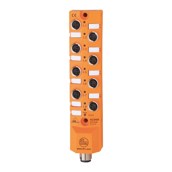
Page 7: Operating And Display Elements
6.2 Data bits AC2489 Data bit Input Socket 7 Operating and display elements M8x1 FAULT M12x1 LEDs I-x 8 Operation LED I-x yellow: Input switched LED PWR green: AS-i voltage supply OK LED FAULT red lights: AS-i communication error, slave does not participate in the "normal"...
Need help?
Do you have a question about the AC2488 and is the answer not in the manual?
Questions and answers