Table of Contents
Advertisement
Quick Links
Advertisement
Table of Contents

Summary of Contents for IFM AC3222
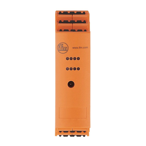
- Page 1 Operating instructions AS-i SmartLine module AC3222...
-
Page 2: Table Of Contents
Contents 1 Preliminary note ���������������������������������������������������������������������������������������������������3 1�1 Explanation of symbols ����������������������������������������������������������������������������������3 2 Safety instructions �����������������������������������������������������������������������������������������������3 3 Functions and features ����������������������������������������������������������������������������������������4 4 Addressing �����������������������������������������������������������������������������������������������������������4 4�1 Addressing with the AC1154 addressing unit�������������������������������������������������4 5 Installation������������������������������������������������������������������������������������������������������������5 5�1 Installation of the device ��������������������������������������������������������������������������������5 5�2 Removal of the device �����������������������������������������������������������������������������������5 6 Electrical connection ��������������������������������������������������������������������������������������������6 6�1 Wiring�������������������������������������������������������������������������������������������������������������6 6�1�1 Connection of a 2-wire Pt100 element �������������������������������������������������7... -
Page 3: Preliminary Note
1 Preliminary note Technical data, approvals, accessories and further information at www�ifm�com� 1.1 Explanation of symbols ► Instructions > Reaction, result → Cross-reference Important note Non-compliance may result in malfunction or interference� Information Supplementary note� 2 Safety instructions • Read this document before setting up the product and keep it during the entire service life�... -
Page 4: Functions And Features
3 Functions and features The slave converts analogue signals (temperature values) into digital values and transfers them to the host� The data transfer is asynchronous according to the AS-i profile S-7�3 and the AS-i specification V2�11� • The slave can be operated in conjunction with a version 2�11 master or higher (master profile M3 or M4). -
Page 5: Installation
5 Installation 5.1 Installation of the device ► Install the device on a 35 mm DIN rail� ► Leave enough space between the unit and the top and bottom of the control cabinet to enable air circulation and to avoid excessive heating� ►... -
Page 6: Electrical Connection
The national and international regulations for the installation of electrical equipment must be adhered to� ► Disconnect power� ► Connect the unit� 6.1 Wiring AC3222 FE FE FE sensor inputs + *) sensor inputs - *) 1+���4+ drive outputs + 1-���4-... -
Page 7: 6�1�1 Connection Of A 2-Wire Pt100 Element
6.1.1 Connection of a 2-wire Pt100 element 1+...4+ The terminals 1+���4+ are intercon- nected in the module� 1-...4- 1: Analogue module 2: Pt100 element 6.1.2 Connection of a 4-wire Pt100 element 4-wire Pt100 sensors supply more exact results than 2-wire sensors provi- ded that the wire resistance is the same�... -
Page 8: Parameter Setting
Important notes for Pt100 measurements With the Pt100 measuring method, very low currents flow into the measuring electronics� Make sure to avoid additional resistance (conductors, contact and transfer resistance, loose contacts, etc.) in the measuring circuit� 4-wire measurement is always to be preferred over 2-wire measurement� For 2-wire measurement, all contact resistances and connection resistances add up by measurement and can falsify the measurement result�... -
Page 9: 7�1 Activation Of The Periphery Fault Message Of The Channels 1
7.1 Activation of the periphery fault message of the channels 1 to 4 By means of the parameter bits P1 and P2 you can define which measuring channels can trigger a peripheral fault message (see table). But irrespective of the defined parameters all 4 channels are always transferred via the AS-Interface�... -
Page 10: Operation
9 Operation ► Check the safe functioning of the unit� 9.1 LED display LED AS-i green lights AS-i voltage supply OK LEDs I1���I4 yellow light analogue signal in the measuring range LEDs I1���I4 yellow flash analogue signal outside the measuring range LEDs I1���I4 yellow off not connected LED FAULT red lights... -
Page 11: Scale Drawing
11 Scale drawing 25,4...


Need help?
Do you have a question about the AC3222 and is the answer not in the manual?
Questions and answers