Table of Contents
Advertisement
Advertisement
Table of Contents

Subscribe to Our Youtube Channel
Related Manuals for IFM AL2400


Summary of Contents for IFM AL2400
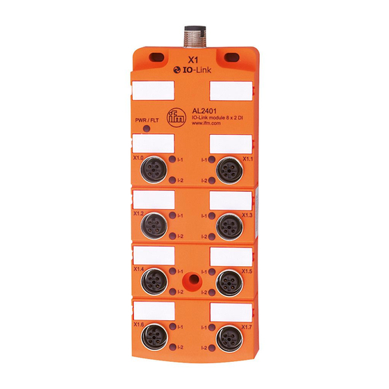
- Page 1 Operating instructions IO-Link CompactLine module AL2400 AL2401...
-
Page 2: Table Of Contents
Content 1 Preliminary note ���������������������������������������������������������������������������������������������������3 2 Safety instructions �����������������������������������������������������������������������������������������������3 3 Functions and features ����������������������������������������������������������������������������������������3 4 Function ���������������������������������������������������������������������������������������������������������������3 4�1 Communication, parameter setting, evaluation ���������������������������������������������3 4�1�1 IO-Link data ������������������������������������������������������������������������������������������3 4�1�2 Visual indication ������������������������������������������������������������������������������������4 4�1�3 Parameter setting ���������������������������������������������������������������������������������4 4�2 Digital inputs ��������������������������������������������������������������������������������������������������4 4�3 Sensor supply ������������������������������������������������������������������������������������������������4 5 Installation������������������������������������������������������������������������������������������������������������5 6 Electrical connection ��������������������������������������������������������������������������������������������6 6�1 Input circuit ����������������������������������������������������������������������������������������������������7... -
Page 3: Preliminary Note
1 Preliminary note ► Instructions > Reaction, result Important note Non-compliance may result in malfunction or interference� Information Supplementary note� 2 Safety instructions • Please read the operating instructions prior to set-up of the device� Ensure that the product is suitable for your application without any restrictions� •... -
Page 4: 4�1�2 Visual Indication
X1�0 Byte 2 (SC) Equipment identification Byte 3 For AL2400 the data bits 4���7 of bytes 0, 1 and 2 are transmitted with '0'� 4.1.2 Visual indication The device - indicates the current state of an input (yellow LED)� - indicates a correct operation (green PWR/FLT LED lights)�... -
Page 5: Installation
5 Installation ► Disconnect power before installation� ► For installation choose a flat mounting surface� The entire bottom of the module must lie flat on the mounting surface� ► Fasten the module onto the mounting surface using M4 screws and washers (1)�... -
Page 6: Electrical Connection
1: M4 screws and washers (not supplied with the device)� Tightening torque 1�8 Nm� 2: M12 connector� Tightening torque 0�8���1�5 Nm� Observe the maximum tightening torque of the connection cable� 6 Electrical connection The unit must be connected by a qualified electrician� The national and international regulations for the installation of electrical equipment must be adhered to�... -
Page 7: 6�1 Input Circuit
Up to 100 mA per sensor supply can be provided, the device itself requires 50 mA� The total current (AL2400 = 450 mA and AL2401 = 850 mA) must be provided by the connected IO-Link master� If the positive supply cable is interrupted the device may be supplied via the IO-Link cable�... -
Page 8: Operating And Display Elements
8 Operating and display elements 1: LED PWR / FLT 2: LED IN 1: LED PWR / FLT 2: LED IN Green LED PWR / FLT lights: everything ok Red LED PWR / FLT lights: short circuit on one or several sensor supplies LED PWR / FLT off: undervoltage or disconnected system Yellow LED IN input lights:... -
Page 9: Maintenance, Repair And Disposal
9 Maintenance, repair and disposal The operation of the unit is maintenance-free� After use dispose of the unit in an environmentally friendly way in accordance with the applicable national regulations� 10 Technical data Technical data and further information at www�ifm�com...
Need help?
Do you have a question about the AL2400 and is the answer not in the manual?
Questions and answers