Table of Contents
Advertisement
Quick Links
Advertisement
Table of Contents

Related Manuals for IFM AC010S


Summary of Contents for IFM AC010S
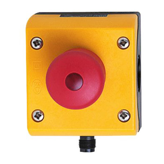
- Page 1 Original operating instructions Compact AS-i E-STOP safety module AC010S...
-
Page 2: Table Of Contents
Contents 1 Preliminary note ���������������������������������������������������������������������������������������������������3 1�1 Explanation of symbols ����������������������������������������������������������������������������������3 2 Safety instructions �����������������������������������������������������������������������������������������������3 2�1 Safety-related requirements regarding the application ����������������������������������4 3 Items supplied������������������������������������������������������������������������������������������������������4 4 Functions and features ����������������������������������������������������������������������������������������4 5 Function and electrical connection ����������������������������������������������������������������������5 6 Installation������������������������������������������������������������������������������������������������������������6 6�1 Operating and display elements ��������������������������������������������������������������������6 7 Electrical connection ��������������������������������������������������������������������������������������������7 8 Addressing �����������������������������������������������������������������������������������������������������������8 9 Operation �������������������������������������������������������������������������������������������������������������8... -
Page 3: Preliminary Note
1 Preliminary note Technical data, approvals, accessories and further information at www�ifm�com� The instructions are part of the unit� They are intended for authorised persons according to the EMC, Low Voltage and Machinery Directive and safety regulations� The instructions contain information about the correct handling of the product�... -
Page 4: 2�1 Safety-Related Requirements Regarding The Application
► Replace damaged units� 3 Items supplied 1 compact AS-i E-STOP safety module, 1 AC010S operating instructions with the reference number 80269280� If one of the above-mentioned components is missing or damaged, please contact one of the ifm branch offices�... -
Page 5: Function And Electrical Connection
When operated correctly, the system can be used in applications up to the Performance Level e according to EN ISO 13849-1 or IEC 61508/SIL3 (see notes Electrical connection). Depending on the safety components used the complete safety system can also be classified for a lower control category! 5 Function and electrical connection Please refer to all information in the description of the configuration software (e�g�... -
Page 6: Installation
Maintenance requirement A minimum of one testing per year is compulsory by a demand on the safety function! 6 Installation ► Fasten the compact AS-i E-STOP safety module onto a mounting device� The upper part of the housing must be fixed to the lower part using all four screws! 6.1 Operating and display elements 1: M12 connector 2: LEDs... -
Page 7: Electrical Connection
7 Electrical connection Connect the compact AS-i E-STOP safety module to the AS-i system via the M12 connector� The supply comes from the AS-i system� Do not connect the AS-i potential to an external potential� M12 connector AS-i - AS-i + M12 connector AS-i + AS-i -... -
Page 8: Addressing
The code words 0000, XX00 and 00XX cause the AS-i safety monitor to bring the installation into the safe state� For more details on the effect of the data bits on the transmission sequence refer to the configuration software manual (see the chapter "Monitoring devices"). 8 Addressing When mounted the compact AS-i E-STOP safety module can be addressed via the M12 connector and the jumper cable, e�g�... -
Page 9: Safety Characteristics
50 ms before application of the signal to AC010S until the safe outputs of the safety monitors switch� Here, the switching times of the external relays and contactors connected to the relay output of the safety monitor have not been taken into account�... -
Page 10: Technical Data
Explanation of the abbreviations: Safety Integrity Level Safety Integrity Level SIL 1-4 to IEC 61508� The higher the SIL the lower the probability that a safety function will fail� Performance Level Capability of safety-related parts to perform a safety function at predictable conditions to fulfil the expected risk reduction�... -
Page 11: Scale Drawing
ID code B�E [Hex] AS-i certificate 74601 Maximum number of compact AS-i E-STOP safety modules EN 61000-6-4; EN 62026-2 Housing materials PC-GF20 (polycarbonate) Housing dimensions 80 x 72 x 105 mm (HxWxD) Connection M12x1 connector 12 Scale drawing 93,5 66,5... -
Page 12: Troubleshooting
13 Troubleshooting The LEDs of the compact AS-i E-STOP safety module indicate faulty operating states ( → chapter 9 Operation). 14 Maintenance, repair and disposal If used correctly no maintenance and repair measures are necessary� Only the manufacturer is allowed to repair the unit� After use dispose of the unit in an environmentally friendly way in accordance with the applicable national regulations�...
Need help?
Do you have a question about the AC010S and is the answer not in the manual?
Questions and answers