Table of Contents
Advertisement
Quick Links
Advertisement
Table of Contents

Related Manuals for Hyd-Mech PH 211


Summary of Contents for Hyd-Mech PH 211
- Page 1 USE AND MAINTENANCE MANUAL PH 211 YEAR OF MANUFACTURE: ______________...
-
Page 3: Table Of Contents
Introduction and technical specifications ..... . 1---1 Foreword ............1---1 Machine presentation . - Page 4 Motor assembly ........... . 6---6 Handle assembly .
- Page 5 Standard or splayed set ..........9---6 Undulated set .
-
Page 7: Introduction And Technical Specifications
Introduction and technical specifications Foreword Hyd---Mech in response to modern production techniques, has developed the new PH211. This work tool has been designed to satisfy the wide range of cutting needs of a modern workshop with simplicity and reliability, while at the same time comply- ing with all EEC safety standards. -
Page 8: Machine Specification
Machine specification Name plate The anodised aluminium name plate is riveted on the side of the machine; the same data are reproduced on the declaration of conformity included with this use and maintenance manual. The Rock Solid Solution PH101 model air pressure oil pressure data code... - Page 9 LUBRICANT/COOLANT FLUID AND OIL Oil for transmission box capacità Kg 0,32 Lubricant/coolant fluid (oil concentration 5---6%) capacità Lt VICE Vice max. opening SPINDLE MOTOR No.of poles Current (Volts) Absorption Power (Kw) Band saw spe- (Amps) 230/400 4,1/3,0 2950 80 mt/min 230/400 2,4/1,7 1430...
-
Page 10: Dimensions
Dimensions MACHINE INSTALLED Work table height Weight 1600 1280 PACKED WEIGHT Wooden cage and pallet Wooden pallet Use and maintenance manual PH211 1- -4... -
Page 11: Functional Parts
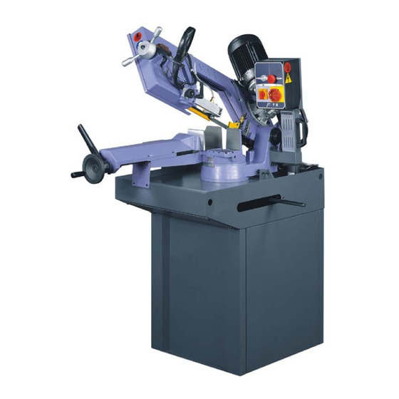
Functional parts PH211 model In order for the user to move towards a full understanding of how the machine works, which is described in detail in the chapter 5, this chapter deals with the main units and their locations. Cutting head The cutting head is the unit that cuts the material. -
Page 12: Vice
Vice The vice is the unit that clamps the workpiece in place during cutting; it consists of a vice support, commonly known as a lead nut, fixed to the work table, and a lead screw with a slideway on which the mobile jaw is mounted. The vice is operated manually by a handwheel, or by a pneumatic cylinder in the MA version (optional). -
Page 13: Safety And Accident Prevention
Safety and accident prevention The PH211 has been designed and produced in accordance with European standards. For the correct use of the machine we recommend that the instruc- tions contained in this chapter are carefully followed. Use of the machine The PH211 band saw cutting machine is intended exclusively for cutting metallic materials, ferrous or non---ferrous, in section or solid. -
Page 14: General Recommendations
General recommendations LIGHTING Insufficient lighting for the types of operation envisaged could constitute a safety hazard for the persons concerned. For this reason, the machine user must provide lighting in the working area sufficient to eliminate all shadowy areas while also avoiding any blinding light concentrations. -
Page 15: Recommendations To The Operator
Recommendations to the operator Always wear proper goggles or protective glasses. Do not use the machine without the guards in position. Do not allow hands or arms to encroach on the cutting zone while the machine is in operation. Do not wear oversize clothing with long sleeves, oversize gloves, brace- lets, necklaces or any other object that may become entangled in the ma- chine during working;... - Page 16 The operator must not perform any risky operations or operations not required for the machining operation under way (e.g. remove swarf or metal shavings from the machine while cutting). Remove equipment, tools or any other objects from the cutting zone; al- ways keep the working area as clean as possible.
-
Page 17: Machine Safety Devices
Machine safety devices This use and maintenance manual is not intended as purely a guide for the use of the machine in a strictly productive environment, it is instead an instrument providing information on how to use the machine correctly and safely. The following standards are those specified by the EEC Committee in the directives regarding safety of machinery, health and safety at work, personal protection and safeguarding of the environment. -
Page 18: Protection Against Accidental Contact With The Blade
Protection against accidental contact with the blade 1. Metal guard screwed to the rear blade guide head (machine side); 2. metal guard screwed to the front blade guide head (operator side); 3. front head sliding support: when the head is at maximum aperture, the sup- port ensures that the blade is covered, leaving free only the part of the blade engaged in the actual cutting, in accordance with Presidential Decree no. -
Page 19: Emergency Devices
Emergency devices In accordance with Standard CEI 204---1: Chapter 5 Section 6 Sub- -section 1 “Emergency stop device”: «the emergency stop device immediately stops all the dangerous and other functions of the ma- chine»; Chapter 6 Section 2 Sub- -section 4 Point 7 “Protective guards”: «the removal of protective guards designed to prevent access to dangerous parts or zones causes the machine to stop immediately;... -
Page 20: Noise Level Of The Machine
Noise level of the machine Noise can cause hearing damage and represents one the problems faced by many countries who adopt their own standards. In accordance with the EEC MA- CHINES DIRECTIVE 98/37/CE , we are listing the standards that specify noise levels for machine tools. -
Page 21: Vibration Emission
Vibration emission This sawing machine complies with the norms EN1299 and EN1033, as the machine vibration emission on the devices controlled by the operator does not exceed the threshold of 2.5 m/s Electromagnetic compatibility As from 1 January 1996 all electrical and electronic appliances bearing the CE marking that are sold on the European market must conform to Directive 89/336/EEC and 70/23/CEE and 98/37/CEE. - Page 22 IRRADIATED EMISSIONS Gate Freq. (MHz) Q--- peak limit (10 m) Result (dBuV/m) Enclosure 30 --- 230 Complies 230 --- 1000 Immunity CEI EN 61000- -6- -2 (2000) Electromagnetic Compatibility (EMC) - - Generic stan- dard on immunity. Part 6- -2: Industrial Environment. The EUT is deemed to fulfil the immunity requirements without testing, because it contains no electonic control circuitry.
-
Page 23: Machine Installation
Machine installation Packaging and storage Hyd---Mech use packing materials that guarantee the integrity and protection of the machine during its transport to the customer. The type of packing differs according to the size, weight and destination. Therefore the customer will receive the machine in one of two following ways: 1. - Page 24 Do not handle the packed machine using slings. Attention When storing, machines palletized and shrink--wrapped must not be stacked Attention two high, and machines pallettized and crated must not be stacked three high. To install the machine, first remove the packing, paying particular attention not to cut any electric wires or hydraulic hoses;...
- Page 25 1. remove nails and lift the top of the cage; 2. remove nails and lower walls; 3. remove heat---shrink covering; 4. remove the straps; 5. remove nails from pallet securing planks and remove planks; 6. remove the front panel and insert fork tines. To locate the machine in the workplace, the machine dimensions and necessary operator working space, including the spaces laid down in safety standards, must be taken into account.
-
Page 26: Anchoring The Machine
Anchoring the machine The base of the machine is anchored to the floor by two permanent studs located on the sides of the base. The studs are screwed into nuts previously sunk into the concrete, and tightened from above with lock nuts. The schematic specifications set out in Chapter 1 should be taken into account when positioning the machine. -
Page 27: Check List
Check list Before starting installation, check that all the accessories, whether standard or optional, supplied with the machine are present. The basic version of the PH211 2---SPEED machine is supplied complete with: CHARACTERISTICS STANDARD OPTIONAL Steel base with coolant tank and electric pump for band lubricating and cool- Double return spring for head upstroke Bimetal blade for solid and section materials Vice with quick clamping lever... -
Page 28: Balancing The Cutting Head
Balancing the cutting head Before making the electrical connections, the head return springs must be tensioned to balance the cutting head weight. Using a 10 mm. wrench, tighten the screws until the distance between the first coil of the spring and the bracket is 8 Connection to the power supply Before connecting the machine to the power supply, check that the socket is not connected in series with other machines. - Page 29 " Insert the plug in the socket, ensuring that the mains voltage is the same as that for which the machine has been setup. VOLT ? VOLT ? " Power up machine by rotating the main switch located on the right side of the control panel (The STAND BY LED lights up).
- Page 30 " operate the jog button on the manual head control lever; " if all the above operations have been carried out correctly, the blade motor will start up and the blade will start rotating. Ensure that the blade moves in the correct direction as shown in the abo- Attention ve figure.
-
Page 31: Description Of Machine Operation
Description of machine operation This chapter analyses all the machine functions. We begin with a description of the pushbuttons and other components on the control panel. Description of the control panel The components of the PH211 control panel are shown in the diagram below. Each arrow has a number which corresponds to the descriptions that follow. - Page 32 1 - LED STAND BY This either confirms machine start up or indicates an emergency state to the operator. 2 - START BUTTON During normal operation of the machine, this enables or disables the cutting cycle start button. 3 - EMERGENCY STOP MUSHROOM BUTTON Pressing this button immediately stops machine operation.
-
Page 33: Basic Instructions For Carrying Out A Cutting Operation Cycle
Basic instructions for carrying out a cutting operation cycle Manoeuvring the cutting head Cutting head movement is facilitated by perfect balancing of the head weight, thanks to the traction force exerted by the two return springs located at the back of the machine. -
Page 34: Width Of Cut
Width of cut The machine is fitted with protections which protect the entire blade stroke, leaving exposed only the part of the blade required to make the cut itself as specified by current standards. The width of the cut is determined by the longitudinal section of the workpiece, so that only the part of the blade required to make the cut is actually exposed. -
Page 35: Preliminary Check List For Cutting Operation
Preliminary check list for cutting operation To guarantee complete safety during cutting cycles, the operator should work through a check list of the entire apparatus, checking: " blade tension; " that the blade guide head bracket is locked in the correct position; "... - Page 36 " Grip the head control lever and start the blade rotating by pressing the micro- switch on the handgrip; the downstroke speed of the head is manually con- trolled by the operator. " The motor starts up and sets the blade in rotary motion; the lubricant/coolant pump starts up at the same time.
-
Page 37: Angled Cuts
Angled cuts The machine can make angled cuts from 60˚ left to 45˚ right. Reference stops are mounted on the sides of the turntable to facilitate rapid 0˚, 45˚ and 60˚ cuts to the left and 45˚ cuts to the right. Angled cuts 45˚... -
Page 38: Angled Cuts 60˚ To The Left
" Relock the turntable lock/release lever. " Make the cut in the required operating mode, following the preliminary safety instructions set out in this chapter. Angled cuts 60˚ to the left " Slacken the turntable lock/release lever; " pull the eccentric pin knob towards you (0˚reference stop) and rotate slightly to raise it;... -
Page 39: Diagrams, Exploded Views And Replacement Parts
Diagrams, exploded views and replace-- ment parts This chapter contains functional diagrams and exploded views of the PH211. This document is intended to help in identifying the location of the various compo- nents making up the machine, giving information useful in carrying out repair and maintenance operations;... -
Page 40: Standardised Wiring Diagrams Hb (Single
Standardised Wiring Diagrams HB (single- -phase) Use and maintenance manual PH211 6- -2... -
Page 41: Standardised Wiring Diagrams (Three
Standardised Wiring Diagrams (three- - phase) Diagrams, exploded views and replace-- 6- -3... -
Page 42: Exploded Views
Exploded views This part of the manual contains detailed exploded views of the machine which can help to gain a deeper knowledge of how it is made. Body frame assembly Use and maintenance manual PH211 6- -4... - Page 43 Code Description Quantity 001.6101 BODY FRAME 001.6105 ANCHOR BLOCK 010.2135 SHAFT 010.1801 HEX. SOCKET HEAD SCREW 025.0273 ANTI--CHIP COVER 025.0072 TAPERED BEARING 010.1201 WASHER 010.1201 HEX. HEAD SCREW 010.1201 HEX. NUT 025.0966 BEARING 034.0291 KNOB 034.0291 BLADE TENSION HANDLE 010.4063 SPRING WASHER 010.3704 LEADSCREW...
-
Page 44: Motor Assembly
Motor assembly Handle assembly Use and maintenance manual PH211 6- -6... - Page 45 Code Description Quantity 034.0423 COVER 010.1201 HEX. SOCKET HEAD SCREW 010.1201 SPRING WASHER 019.2331 MOTOR 010.1201 HEX. SOCKET HEAD SCREW 010.1201 SPRING WASHER 025.0769 REDUCER (2/4P) 010.1201 SPRING WASHER 010.1201 HEX. SOCKET HEAD SCREW 010.1201 HEX. SOCKET HEAD SCREW 010.1201 WASHER 010.1201 ROUND HEAD KEY...
-
Page 46: Blade Adjustable Assembly (Rear)
Blade adjustable assembly (rear) Blade adjustable assembly (front) Use and maintenance manual PH211 6- -8... - Page 47 Code Description Quantity 010.2140 BEARING SHAFT 010.3336 ECCENTRIC GUIDE 025.0901 BEARING 010.1201 C--RETAINER RING 010.3337 ECCENTRIC GUIDE 010.1201 HEX. NUT 010.1201 SPRING WASHER 016.1172 BLADE COVER (REAR) 010.2393 BLADE ADJUSTABLE (REAR) 58--1 010.0868 BRUSH SUPPORT 58--2 025.0552 BRUSH 58--3 010.2068 BUSHING 58--4 010.4062...
-
Page 48: Idler Wheel And Drive Wheel Assembly
Idler wheel and Drive wheel assembly Blade back cover assembly Use and maintenance manual PH211 6- -10... - Page 49 Code Description Quantity 025.0273 ANTI--CHIP COVER 025.0072 TAPERED BEARING 001.6102 IDLER WHEEL 010.0363 010.6103 DRIVE WHEEL 010.1201 DRIVE SHAFT WASHER 010.1201 HEX. HEAD SCREW Code Description Quantity 031.0876 BLADE 016.0949 BLADE BACK COVER 034.1110 HEX. SOCKET HEAD SCREW 010.1201 WASHER 6- -11...
-
Page 50: Control Panel Assembly
Control panel assembly Use and maintenance manual PH211 6- -12... - Page 51 Code Description Quantity 010.4061 SPRING 010.1201 LOCK NET 010.1682 BOLT 031.5002 WARNING PASTER 016.0232 CONTROL BOX BASE 010.1201 HEX. SOCKET HEAD SCREW 010.1201 SPRING WASHER 010.1201 WASHER 367.9133 LABLE FOR NAME PLATE 016.0715 CONTROL SWITCH ASSEMBLY 6- -13...
-
Page 52: Base Assembly
Base assembly Use and maintenance manual PH211 6- -14... - Page 53 Code Description Quantity 025.0967 TAPERED BEARING 025.0277 ANTI--CHIP COVER 031.5001 SCALE 010.1201 RIVET 001.6106 SWIVEL ARM 010.1201 HEX. NUT 010.1201 HEX. HEAD SCREW 010.2070 BUSHING 010.0354 010.2083 COVER 010.1201 HEX. SOCKET HEAD SCREW 010.1201 SPRING WASHER 010.1201 HEX. SOCKET HEADLESS SCREW 034.0900 OIL LEVEL GAGE 034.0903...
-
Page 54: Vise Assembly (A)
Vise assembly (A) Vise assembly (B) PH 211 Use and maintenance manual PH211 6- -16... - Page 55 Code Description Quantity 034.0293 HANDWHEEL 010.1201 010.2085 BEARING COVER 025.0965 BEARING 001.6002 VISE HANDLE 010.0892 SPRING 010.1700 BUSHING 001.6108 VISE JAW BRACKET 010.0528 VISE 010.1201 HEX. SOCKET FLAT HEAD SCREW 010.1201 WASHER 010.1201 HEX. SOCKET HEAD SCREW 010.0237 LEADSCREW A 010.1201 HEX.
-
Page 56: Stand Leg Assembly
Stand leg assembly Use and maintenance manual PH211 6- -18... - Page 57 Code Description Quantity 010.1201 WASHER 010.1201 HEX. SOCKET HEAD SCREW 250--1 013.0203 STAND LEG (FRONT) 250--2 013.0203 STAND LEG (RIGHT) (LEFT) 010.1201 HEX. HEAD SCREW 010.1201 WASHER 010.1201 HEX. NUT 6- -19...
-
Page 59: Adjustments
Adjustments This chapter illustrates the regulations and adjustments of the mechanical systems for correct use of PH211. These instructions will enable you to “custo- mise” your machine to suit the type of cuts you want, optimising the time required to complete them. Vice Vice play adjustment Vise Jaw Bracket has been adjusted in the perfect situation. -
Page 60: Cutting Head
Cutting head Blade tensioning unit Before use the machine, please turn blade tension handle until shore up the screw A. To maintain the blade tension is tightened. Also, make sure the blade tension within green area. How to adjust blade tension: Use and maintenance manual PH211 7- -2... - Page 61 " Loosen the blade tension and set the blade tension indication on the back of blade. " Making the blade tension go back to zero and adjust the blade tension until 2250 Kgs / cm2 (32,000 Lbs / in2) Adjustments 7- -3...
-
Page 62: Adjusting Operating Head Travel
" Take off the blade tension chart and let the screw shore up the blade tension handle. The machine enters emergency status if the blade tension is too slack. A pres- Attention sure contact (pressure switch) disables blade start--up if the blade is not cor- rectly tensioned, since it might otherwise slip off the wheels, cut poorly or wear prematurely. -
Page 63: Blade Guide Parts
Blade guide parts Band saw blade guides offer enormous advantages where the cutting process in concerned, without requiring any special attention by the operator. The blade guide adjustments necessary to ensure that the blade operates correctly are described below. Blade guide heads Blade guide heads are used to carry out a part of the blade adjustment, and include the blade guide bearing to control the longitudinal setup. - Page 64 " open the front blade guard by undoing the fixing screw and rotating it as illus- trated in the figure below; " wear protective gloves when making this adjustment; " make sure there is a small amount of play between the blade and guide plate inserts;...
- Page 65 " if the amount of play is not sufficient for the blade to run smoothly, adjust the locking torque of the two grub screws with an Allen key; " replace any worn plates by removing the plate fixing screw; " repeat the above sequence of steps on the rear blade guide head; "...
-
Page 66: Blade
Blade The adjustments required to ensure correct operation of the blade are described below. For further information about band saw blades, refer to Chapter 9 which provides a more detailed description of the different types of blade. Tool change Optimum working conditions both enhance operator safety and extend the tool’s service life. - Page 67 " remove the rear blade guard by undoing the two fixing screws using an Allen key; " wear protective gloves when changing the blade; " remove the worn blade by sliding it off the flywheels and front and rear heads; "...
-
Page 68: Blade Perpendicularity
Blade perpendicularity The perpendicularity of the blade to the work surface, and also the blade tension, are vital for achieving straight cuts. This adjustment is carried out with the help of a workshop square, which should be placed adjacent to the blade resting on the work surface. -
Page 69: Orthogonality Of The Blade
" Position the square on the work surface close to the front head. " Repeat the squaring operations as for the rear head. Orthogonality of the blade The procedure for correcting and adjusting the blade to 0˚, 45˚ right and 45˚ and 60˚... - Page 70 " Slacken the head locking lever, by gripping it from the operator side and pu- shing it forwards. " Slacken the nut and, holding it firm with a hex wrench, adjust the stop screw until the right angle error shown on the goniometer is corrected. "...
- Page 71 " Operation sequence: " Slacken the head locking lever by pushing it forwards. " With the head raised, rotate the unit to 45˚ or 60˚. " Lower the head. " Position the goniometer or graduated square against the fixed vice jaw, adja- cent to the blade.
-
Page 73: Maintenance And Choice Of Consumables
Maintenance and choice of consumables PH211 is built to be sturdy and long---lasting It has no need of any special maintenance, though, like all other tools, it needs adjusting from time to time, especially if not regularly looked over or used without due care. This chapter, therefore, is intended as a guide for those who want to look after the machine and get the most out of it for as long as possible. -
Page 74: Maintenance Requirements
Maintenance requirements All ordinary and extraordinary maintenance must be carried out with the power switched off and the machine in emergency condition. To guarantee perfect operation, all spare parts must be Hyd- -MEch originals. On completion of maintenance works, ensure that the replaced parts or any tools used have been removed from the machine before starting it up. -
Page 75: Monthly
Monthly This section lists the operations to be carried out for the monthly maintenance of the machine: " check the perpendicularity of the blade to the work surface; if it is necessary to adjust the blade setting, follow the instructions set out in Chapter 7; "... - Page 76 considers that the above product has the best price/quality rapport. The following oils can also be said to have similar characteristics and are therefore compatible: AGIP NB 200 --- SHELL Lutem TT --- IP Utens Fluid---F Finally, a lubricant/coolant guaranteed and distributed by a band saw manufactu- rer (LENOX) is BAND---ADE SAWING FLUID LENOX.
-
Page 77: Cutting Speed And Choice Of Tools
Cutting speed and choice of tools The cutting speed is determined by the blade speed and the head feed speed. While the head speed is provided by the downstroke movement of the head, the blade rotation speed can either be fixed or variable. This chapter describes the cutting speeds the machine can operate at in the standard version, as well as the speeds for which the optional electronic speed controller (inverter) is necessary. -
Page 78: Cutting Speed And Downstroke Speed
Very large dimensions require coarse teeth, while small dimensions require finer teeth. Whatever the case, ensure that there are always at least six teeth engaged in the cut, with reference to the thinnest vertical walls positioned transversally to the blade. Concerning the type of Shark machine, a first broad distinction can be made according to the hardness of materials: <... -
Page 79: Lubricant/Coolant Fluid
Thick and/or blue swarf indicates that the blade is overloaded. Long coils of swarf indicate ideal cutting conditions. Lubricant/coolant fluid The lubricant/coolant fluid must ensure so that neither the saw teeth nor the work piece material in the cutting zone overheat. Furthermore, there must be a sufficient quantity and pressure of lubricant/coolant to remove swarf from the cutting zone. -
Page 80: Blade Structure
Blade structure The most commonly used blades are the bimetal types, i.e. manufactured with a silicon steel body and having a high fatigue strength, and super high---speed steel teeth; the two parts are welded by electronic or laser---welding. Standardised teeth types are termed M2 and M42; the difference being that M42 teeth are harder due to the addition of cobalt to the steel used to make the teeth. -
Page 81: Conventional Rake
Conventional rake Cutting angle 0˚, constant pitch. In general use, for small or medium section cast iron or steels and rolled materials, for straight or angled cuts. Positive rake Positive cutting angle 9---10˚, constant pitch. Can be used for cutting all types of materials, and is particularly suited to low---carbon and non---ferrous steels. -
Page 82: Variable Pitch Blades With 0˚ Cutting Angle
Variable pitch blades with 0˚ cutting angle This type of tooth formation is ideal for cutting single pipes or medium size bundles, in accordance with the capacity of the machine. Pitches available: 3---4 / 4---6 / 5---7 / 5---8 / 6---10 / 8---12 / 10---14. Variable pitch with positive rake (from 9 to 10 degrees) This toothing type is the most suitable for cutting large dimension pipes and profiles, including large sections, as well as for cutting solid sections up to the... -
Page 83: Undulated Set
For general use on materials over 5 mm. thick. Suitable for cutting steels, castings and non---ferrous hard materials. Undulated set Used to describe groups of teeth undulating alternatively to the right and left. This type of set is used with very fine teeth for cutting thin pipe walls and small---section profiles (from 1 to 3 mm). -
Page 84: Blade Selection Table Relating To Cutting Speed And Downstroke Speed
Blade selection table relating to cutting speed and downstroke speed Use and maintenance manual PH211 9- -8... -
Page 85: Classification Of Steels
Classification of steels This page provides a table giving the user specific information on the cutting materials, in order that they can be classified on the basis of their hardness, and thus the correct tool can be selected for the task in hand. Cutting speed and choice of tools 9- -9... -
Page 86: Classification Of Steels 9
Classification of steels Use and maintenance manual PH211 9- -10... -
Page 87: Troubleshooting
Troubleshooting This chapter describes the inspection and troubleshooting procedures for the PH211. Regular inspections and efficient maintenance are essential to ensure your machine gives you a long, trouble---free service life. The chapter is divided into two sections: the first being dedicated specifically to TROUBLESHOOTING BLADE AND CUTTING PROBLEMS, while the second TROUBLESHOOT- ING section concerns troubleshooting general machine operating faults. - Page 88 PROBLEM PROBABLE CAUSE SOLUTION Rapid tooth wear ' Teeth pointing in the wrong .Set teeth in correct direction direction ' Blade worn in wrongly .With a new blade cutting should be done at half--spe- ed and with downstroke spe- ed also at half normal speed. After the blade has been worn in (about 300 cm work for hard cutting ma-...
- Page 89 PROBLEM PROBABLE CAUSE SOLUTION Cuts not orthogonal or inclined ' Head downstroke speed too .Reduce head downstroke fast speed ' Widia inserts worn .Replace ' Inserts loose .Adjust width ' Blade guide head positioned .Move mobile head up to the wrongly workpiece using the guide plate to leave free only that...
- Page 90 PROBLEM PROBABLE CAUSE SOLUTION Broken teeth ' Cutting pressure too high .Check and set to correct pressure ' Tooth pitch unsuitable .Teeth too close together: change blade for one with a coarser tooth pitch ' Swarf welded to teeth and .Check blade--cleaning coo- gullets lant jets.
- Page 91 PROBLEM PROBABLE CAUSE SOLUTION Broken teeth ' Widia inserts positioned in- .Adjust the position of the in- correctly serts, especially the width, since blade thicknesses can exceed the manufacturer’s declared tolerance ratings ' Widia blade steady buttons .Two widia blade steady but- tons are located in the top of the blade guide heads which press on the back of the...
- Page 92 PROBLEM PROBABLE CAUSE SOLUTION Blade path fault ' Front flywheel position incor- .Check that the band saw is rect correctly positioned on the flywheel. Adjust the position of the flywheel under the bla- de, moving the shaft of the flywheel ' Flywheels worn .Replace ' Gaps full of swarf...
- Page 93 PROBLEM PROBABLE CAUSE SOLUTION ' Blade weld fault .The point at which a blade is welded is its most critical point; problems could be caused by welds which are not aligned perfectly or have inclusions or blowholes ' Free blade guide head .The head is too far away from the workpiece: move the head closer, leaving free only...
-
Page 94: Troubleshooting Machine Faults
Troubleshooting machine faults PROBLEM PROBABLE CAUSE SOLUTION ' Electrical supply .Check: phases, cables, plug, The main switch does not work socket ' Minimum voltage relay .Check that it is correctly sup- plied and not burnt out The STAND BY LED does ' LED burnt out .Replace not come on... - Page 95 PROBLEM PROBABLE CAUSE SOLUTION BMT not energised (Minimum ' Electrical power supply .Check: the phases; the Tension Coil) cables; the plug; the socket. ' BMT Reset switch .Make sure that the minimum tension coil is energised when switch is turned from 0 to 1.
- Page 96 CHAPTER 11 - - Warranty Hyd-- Mech Group warrants each new sawing machine to be free from failure resulting from defective material and workmanship under proper use and service for a period of one year following the date of shipment to the user. Hyd--Mech’s sole obligation under this warranty is limited to the repair or replacement without charge, at Hyd--Mech’s factory, warehouse, or approved repair shop, of any part or parts which Hyd--Mech’s inspection shall disclose to be defective.
Need help?
Do you have a question about the PH 211 and is the answer not in the manual?
Questions and answers