Table of Contents
Advertisement
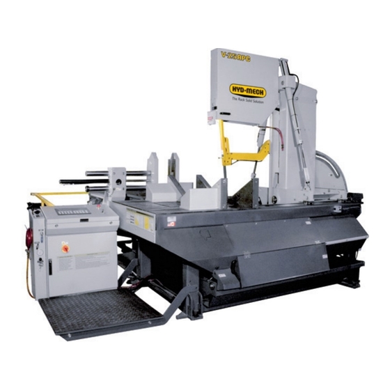
V-25APC
2007
859331
Thank you,
On behalf of everyone at HYD·MECH Group Limited, we would like to thank and congratulate you on your decision to
purchase a HYD·MECH bandsaw.
Your new machine is now ready to play a key role in increasing the efficiency of your operation, helping you to reduce
cost while boosting quality and productivity.
To ensure you are maximizing the power and versatility of your new HYD·MECH bandsaw, please take the time to
familiarize yourself and your employees with the correct operation and maintenance procedures as outlined in this
manual.
We sincerely appreciate the confidence you have demonstrated in purchasing our product and look forward to building
a long and mutually beneficial relationship.
Thank you
Hyd·Mech Group Limited
P.O. Box 1659, 1079 Parkinson Road
Woodstock, Ontario, N4S 0A9
Phone : (519) 539-6341
Service : 1-877-237-0914
Sales : 1-877-276-SAWS (7297)
Fax : (519) 539-5126
info@hydmech.com
e-mail :
Printed June, 2010
1
Advertisement
Table of Contents
Troubleshooting

Related Manuals for Hyd-Mech V-25APC


Summary of Contents for Hyd-Mech V-25APC
- Page 1 V-25APC 2007 859331 Thank you, On behalf of everyone at HYD·MECH Group Limited, we would like to thank and congratulate you on your decision to purchase a HYD·MECH bandsaw. Your new machine is now ready to play a key role in increasing the efficiency of your operation, helping you to reduce cost while boosting quality and productivity.
-
Page 3: Table Of Contents
SECTION 0 - SAFETY INSTRUCTIONS SUMMARY ............................0.1 BASIC RULES ..........................0.3 SAFETY HAZARD LABELS ......................0.6 LOCATION AND PART NUMBERS OF SAFETY HAZARD LABELS ON V-25APC ......0.8 SECTION 1 - INSTALLATION SAFETY CONSIDERATIONS ......................1.1 V-25 APC LIFTING AND SHIPPING....................1.2 LEVELING THE V-25 APC .......................1.3 BARFEED INSTALLATION ......................1.4... - Page 4 BLADE BRUSH ADJUSTMENT .......................3.8 BLADE WIPERS..........................3.8 LUBRICATION ..........................3.9 OUTPUT SHAFT LUBRICATION ....................3.10 GEARBOX LUBRICATION (V-25APC WITH A503 GEARBOX) .............3.10 HYDRAULIC MAINTENANCE ......................3.11 TROUBLE SHOOTING GUIDE .......................3.12 SECTION 4 - ELECTRICAL FOR ELECTRICAL SCHEMATICS AND COMP. PARTS LISTS SEE PDF ON ATTACHED CD ..4.1 SECTION 5 - HYDRAULICS FOR HYDRAULIC SCHEMATICS AND PLUMBING DIAGRAMS SEE PDF ON ATTACHED CD ...5.1...
-
Page 5: Summary
SECTION 0 - SAFETY INSTRUCTIONS SUMMARY All persons operating this machine must have read and understood all of the following sections of this Manual: Section 0 SAFETY Section 2 OPERATING INSTRUCTIONS However, as a memory aid, the following is a summary of the Safety Section. Put Safety First Mandatory Information –... - Page 6 FOREWORD Put Safety First! This Safety Section contains important information to help you work safely with your machine and describes the dangers inherent to bandsaws. Some of these dangers are obvious, while others are less evident. It really is important to PUT SAFETY FIRST. Make it a habit to consider the hazards associated with any action BEFORE you do it.
-
Page 7: Basic Rules
Manual, and When all operations and procedures are in compliance with this Manual. Hyd-Mech Group cannot accept any liability for personal injury or property damage due to operator errors or non-compliance with the Safety and Operating Instructions contained in this Manual. - Page 8 Define responsibilities Clearly define exactly who is responsible for operating, setting-up, servicing and repairing the machine. Define the responsibilities of the machine operator and authorize him to refuse any instructions by third parties if they run contrary to the machine’s safety. Persons being trained on the machine may only work on or with the machine under the constant supervision of an experienced operator.
- Page 9 Clothing, jewellery, protective equipment Personnel operating or working on the machine must not wear un-restrained long hair, loose-fitting clothes and dangling jewellery. When operating or working on the machine, always wear suitable, officially tested personal protective equipment such as safety glasses and safety boots and any other equipment required by plant regulations.
-
Page 10: Safety Hazard Labels
On Hyd-Mech machines the Master Disconnect Switch will be of one of three types: • Rotary switch mounted in electrical control cabinet door and inter-locked with door. - Page 11 MOVING BANDSAW BLADE WILL CUT Do NOT operate with guard removed. Do NOT place hands or fingers near moving bandsaw blade. For blade changing, always follow the proper Blade Changing Procedure, as given in Section 3 of this manual. PINCH POINT Machine parts may move without warning, either because the machine is operating automatically, or because another person initiates the motion.
-
Page 12: Location And Part Numbers Of Safety Hazard Labels On V-25Apc
LOCATION AND PART NUMBERS OF SAFETY HAZARD LABELS ON V-25APC DANGER Hazardous voltage inside Item N0. 391938 DANGER Moving bandsaw blade will cut Item N0. 391937 The following pictures on the next page show the locaton of label: WARNING Pinch Point... - Page 14 The following pictures show the locaton of label: DANGER. Moving parts can crush and cut. Keep hands clear. DANGER Moving parts can crush and cut. Keep hands clear. Item N0. 391335 0.10...
- Page 15 The following pictures show the locaton of labels : 1. DANGER. Moving parts can crush and cut. Keep hands clear. 2. CAUTION. Do NOT step or stand on this surface. CAUTION Do NOT step or stand on this surface. Item N0. 391632 0.11...
- Page 16 0.12...
-
Page 17: Section 1 - Installation
The area around the machine should be kept clean and tidy. The V-25 APC machine should be used according to its specifications. The operator must wear eye protection. No modifications to the machine are allowed without Hyd-Mech’s prior approval. Any approved modifications shall be performed by trained personnel. -
Page 18: V-25 Apc Lifting And Shipping
V-25 APC LIFTING AND SHIPPING The shipping weight of the V-25 APC is 10000 lb. The front-to-rear location of the centre of gravity is midway between the chain holes on the lifting angles. Side-to side the centre of gravity is about 7” to the right of the centre line of the saw table. -
Page 19: Leveling The V-25 Apc
LEVELING THE V-25 APC It is important that the V-25 APC sit solidly on all four leveling bolts, and that the saw table be level. The V-25 APC is stable in all head positions, and it is not necessary to bolt the saw directly to the floor. The leveling plates provided have a dimple for the leveling bolt to sit in, and two holes for lagging the plate to the floor. -
Page 20: Barfeed Installation
BARFEED INSTALLATION 1. The shipping weight of the barfeed is 5000 lb. Place one lifting sling around the front horizontal cross member located 28” back from the front of the conveyor. Place another sling around the cross member located 15” forward of the rear of the conveyor. - Page 21 3. Connect the three lower struts that assemble the front leg of the barfeed to the saw. The finished gap between the front plate of the conveyor and the rear plate of the machine is to be 5/8” +/- 1/8”. The alignment between the barfeed and machine should be checked quickly with a 10’...
- Page 22 4. The six levelling plates should be lagged to the concrete floor with ¾” x 4¾” heavy duty concrete wedge anchors and strong tack welds should be placed at all six areas. As mentioned earlier, the conveyor should be leveled in both directions; across and along the infeed conveyor. Six level- ing screws are provided, three down each length of the conveyor.
- Page 23 6. The cable trough is located by four L-shaped brackets; two hooked into each front and rear conveyor legs. Fasten two of the brackets to the front end of the cable trough and then place them into the slots at the front conveyor leg. Slide the other two brackets through the slots of the rear leg and fasten them to the cable trough.
- Page 24 8. Fasten the cable track upper bracket to the back of the carriage box centre. 9. Remove the datum vise toggle cover - three 3/8 NC bolts on top, and two 3/8 NC bolts on the underside. Install the rod end of the cylinder with the 1/2 NF x 1.50 socket bolt.
- Page 25 10. Feed the hoses for the movable vise cylinder (#61 and #62) along with the out-of-stock limit switch cord (C23) up along the movable vise post. Connect hose #61 at the needle valve and hose #62 at the cylinder gland. Connect cord C23 to the out-of- stock limit switch.
- Page 26 12. Fasten the rear guard rail to the barfeed rear leg with the provided fasteners. 13. Fasten the shuttle datum side guard to the machine with the bolts provided. 14. Fasten the shuttle movable side guard to the control console with the provided hex bolts.
- Page 27 16. Attach the eyebolt to the shuttle datum side guard. Fasten the wire rope to the spring and then proceed to feed it through the eyebolts and pulleys along the guide rail. Loop the other end of the wire rope around the eyebolt of the trip wire control box.
-
Page 28: Conveyor Installation (Optional)
AND CONFIDENTIAL.REPRODUCTION,PUBLICATION OR X.X =/- 0.5 DEG .X +/- .015 IN DISTRIBUTION OF ANY PART REQUIRES WRITTEN CONSENT OF HYD-MECH GROUP.THIS DATA IS THE PROPERTY OF .XX +/- .010 IN HYD MECH GROUP AND ITS POSSESION CONFERS NO THIRD ANGLE PROJECTION .XXX +/- .005 IN... -
Page 29: Cutting Fluid
CUTTING FLUID As the V-25 APC operates with an open reservoir to contain the cutting fluid, no cutting fluid can be shipped with the saw. There are two main types of cutting fluids available, oil based and synthetic. For oil based fluids the dilution ratio is 1:10. One part concentrate to ten parts water. -
Page 30: Earth Grounding Procedure
EARTH GROUNDING PROCEDURE The customer is to provide and install a ground rod approx.. .60 (15mm) diameter, copper clad steel, to be driven no less than 8’ (2.5m) into the ground, no more than 10’ (3m) away from control enclosure. The ground rod is to be connected to customer’s in plant ground system. -
Page 31: Section 2 - Operating Instructions
SECTION 2 - OPERATING INSTRUCTIONS E300 Interface Operation Instructions PLC 500 CONTROL SYSTEM OPERATION OVERVIEW The PLC is a programmable logic controller that allows the operator to run the machine in both manual and automatic modes. The control panel is divided into four parts: MANUAL ONLY on the left; MANUAL & AUTO in the centre; MACHINE on the right;... -
Page 32: Manual Mode Only Controls
MANUAL MODE ONLY CONTROLS HEAD CONTROLS Pressing this key will swing the head clockwise and will stop and hold its position if the key is released. Will HEAD SWING RIGHT not swing unless the Guide Arm is in the full upward position and the Head is retracted fully. Pressing this key will swing the head counter-clockwise and it will stop and hold its position if the key is HEAD SWING LEFT released. -
Page 33: Machine & Cycle Controls
The SERVICE MODE allows the user to adjust the various PLC parameters. The user will be prompted for a SERVICE MODE password. Contact Hyd-Mech Group Limited to access this mode. MANUAL MODE Pressing this key will enable all of the “MANUAL MODE ONLY CONTROLS.”... -
Page 34: Optional Equipment Controls
OPTIONAL EQUIPMENT CONTROLS LASER ON / OFF Pressing this key will cause the LASER to turn on or off. The red LED indicates that the LASER will be on. *** SHUTTLE BUNDLING CONTROLS *** SHUTTLE BUNDLING Pressing this key will open the shuttle bundling clamp. It will stop and hold its position if the key is released. OPEN Activating this push button (LED is on) before entering AUTO MODE will allow the shuttle bundling clamp to SHUTTLE BUNDLING... -
Page 35: Manual Mode
MACHINE START UP Reset the E-Stop by pulling out the red mushroom button. There is a short delay to allow the machine software to load. Press the machine start button two times: First to wake up the screen saver, and then a second time to start the hydrau- lics. -
Page 36: Collision Detection Feature
To return to previous screen press exit key. The Standard kerf and corrected values are as follows: STD KERF @ 90° 75° 60° 55° 50° 45° 40° 35° 30° 1 ¼” BLADE .066 .068 .076 .081 .086 .093 .103 .115 .132 1 ½”... -
Page 37: Parameters
PARAMETERS The parameters can be accessed by pressing the service mode button on the panel. These parameters can be changed without a password. 1. COOLANT ON WHEN BLADE RUN: __ / AND HD. AD In Automatic Mode - Allows the coolant to flow whenever the blade is running or when the blade is running and the head advances. - Page 38 PARAMETER DEFINITION MATERIAL INFEED Defines the infeed side of the machine MACHINE MODEL Defines vertical (V25APC) or metering (M20APC) models GUIDE ARM SENSOR RES. Specifies linear distance of guide arm movement in pulses per inch LENGTH ENCODER Specifies linear distance of shuttle movement in inches per one pulse generated RESOLUTION by motion controller.
-
Page 39: Opening The Front Gate In Manual And Automatic Mode
OPENING THE FRONT GATE IN MANUAL AND AUTOMATIC MODE To open the front gate during MANUAL MODE, the following steps need to be done in the following sequence: NOTE: Before opening the front gate in MANUAL MODE, make sure that the head swing and shuttle movements are not activated. -
Page 40: One Cut Mode Operation
ONE CUT MODE OPERATION In MANUAL mode, the PLC allows the operator to initiate a ONE CUT MODE to cut one piece at a desired length. To accomplish this, follow the procedure below. 1. A trim cut should be made before initiating the ONE CUT MODE operation. Key in the required angle using the keypad and cursors, press “AngleGo”... - Page 41 3. Immediately after entering the AUTO mode, the JOB screen will be displayed with the cursor located at “A1 of JOB #1” (See Below). Both the ENTER button or the cursor key can be used to move through this screen. There are three ways to navigate between pages: PG UP (Page Up) –...
-
Page 42: Sequence Of Operation
13. After the values are entered, press the START button. The display window will prompt you to Input Material Height. This will control the guide arm position (if the guide arm automatic control parameter is activated). 14. The display will prompt you to press Cycle Start to initiate Job Queue. JOB LIST 15. -
Page 43: Mechanical Controls
MECHANICAL CONTROLS HEAD FORWARD LIMIT SETTING The Head Forward Limit is factory set and under normal op- erating conditions should not need to be reset. It functions by stopping head advance and shutting off the blade when it has advanced to meet the left hand movable vise jaw. TO SET LIMIT: If adjustment of the head stopping position with respect to the vise jaw is necessary, the split shaft collar on the vise cylinder... -
Page 44: Out Of Stock Collar
OUT OF STOCK COLLAR The collar is located on the lower guide shaft of the barfeed’s movable vise, and is locked in position by a brass thumbscrew. The action of the collar is to trip a limit switch and shut down the saw when the vise closes without encountering a work piece. -
Page 45: Section 3 - Maintenance & Trouble Shooting
SECTION 3 - MAINTENANCE & TROUBLE SHOOTING SAFETY DURING MAINTENANCE AND TROUBLESHOOTING “Lock-Out”, or “Lock-out Tag-out” are terms that refer to procedures taken to prevent the unexpected start-up, or other release of energy, by a machine, whenever anyone is required to remove or bypass safety devices, or whenever anyone is required to place part of his body in a hazard area. -
Page 46: Blade Change Procedure
BLADE CHANGE PROCEDURE Wear safety glasses, gloves, and a long sleeve shirt for protection when handling bandsaw blades during blade change. NOTE THAT GLOVES SHOULD NEVER BE WORN NEAR A RUNNING BANDSAW BLADE. When handling new blades, or ones that will be re-used, it is important to keep the teeth out of contact with concrete floors. - Page 47 5. The V-25APC blade is only exposed to the operator at the cutting area. A blade guard protects the operator from the blade between the drive wheel assembly and the actual cutting area. A black knob on the cover allows it to be swung open.
-
Page 48: Blade Installation
BLADE INSTALLATION NOTES ABOUT NEW BLADES: • It is helpful to have two people to install a new blade. • A new blade will come folded into a compact coil. Follow the blade manufacturer’s instructions for safely unfolding blade. • The blade must be installed with the teeth facing out towards the right hand side of the saw where it passes around the wheels, and with the teeth in the cutting area pointing down towards the idler wheel. -
Page 49: Blade Tracking
(1.5” across flats) hex bolt, and locked by a concentric round head socket screw. Hyd-Mech Service should be contacted before making any adjustment to lateral wheel position. The angular position of the blade wheels: Although apparently parallel to each other, the blade wheels are tilted slightly and adjustment of the tilt of each wheel is the primary method of adjusting blade tracking. -
Page 50: Drive Wheel Adjustment
DRIVE WHEEL ADJUSTMENT Adjustments should be made with the blade tension released slightly. The drive wheel assembly is mounted on the drive arm weldment which has two set screws and a hex bolt in a “push/pull” arrangement. Gain access to these adjusters by removing the cover plate on the head upper side cover. -
Page 51: Blade Guides
BLADE GUIDES The blade is twisted and guided by upper and lower guide block assemblies. These are almost identical except that the upper assembly contains a coolant gallery, and the lower guide is externally tapered on an angle to allow it to sit closer to the underside of the table. -
Page 52: Blade Brush Adjustment
Adjusting Screw Assembly Dowel Pin - Hinge Removal of the front plate completely exposes the internals of the guide block assembly as shown in the photos above. The side carbides are mounted by #6-32 flat head socket screws which engage lock nuts on the outside of the plates. The back plate holds the square pivoting carbide insert that correspond to the “top”... -
Page 53: Lubrication
LUBRICATION The V-25APC was designed with a goal to minimize the maintenance required so as to reduce downtime. We recommend that periodic lubrication be done once a month using any general purpose grease. The following photos show the location of grease fittings that should be lubricated monthly. -
Page 54: Output Shaft Lubrication
Because of the tilted orientation of the gearbox on the V-25APC, the correct oil level is to the bottom of the fill plug “A” shown in the photo. The gearbox can also be filled at the breather shown in the photo. -
Page 55: Hydraulic Maintenance
The hydraulic tank capacity is 8 US gallons. NOTE: The V-25APC is shipped from the factory with Texaco Rando HD 46 oil. Generally any brand of recognized min- eral hydraulic oil with the same properties should be compatible with Texaco Rando HD 46 oil, but to avoid any risk we suggest staying with Texaco Rando HD 46. -
Page 56: Trouble Shooting Guide
Most problems which may occur have one of the relatively simple solutions which appear in this section. If the solution is not found here, contact the Hyd-Mech Distributor from whom you purchased your bandsaw. They have trained field serv- ice personnel who will be able to rectify the problem. - Page 57 CUTTING AND BLADE TROUBLESHOOTING PROBLEMS CAUSE SOLUTION 1.1 Head is not set at 90 degrees. 1.1 Re-position head. Saw is cutting out of square from top to bottom. 1.2 Blade guide(s) not closed. 1.2 Close guide adjusters fully. Review settings using Blade Basics Excessive feed rate or feed force and Cutting Parameters Chart in settings.
- Page 58 10.1 Feed Rate pointer misaligned. 10.1 Position the pointer to “0” and 10 Head advances with set to “0”. tighten lock nut. Fast approach valve is open. Adjust fast approach lever. Phone 10.2 10.2 Blocked lever. Hyd-Mech Service for details. 3.14...
-
Page 59: Section 4 - Electrical
SECTION 4 - ELECTRICAL ELECTRICAL SCHEMATICS: SEE PDF ON ATTACHED CD... -
Page 61: Section 5 - Hydraulics
SEE PDF ON ATTACHED CD The V-25APC hydraulic system does not require any special work on a new machine before its start-up. The hydraulic tank is filled with Texaco Rando HD 46 oil and all machine functions have been tested at the factory to ensure the proper operation upon start-up. -
Page 62: Gland & Piston Assemblies
CYLINDER ASSEMBLIES GLAND ASSEMBLIES CYLINDER DIAMETER O RING BACKUP GLAND LOADED WIPER O RING U CAP 2.0” 362960 362785 CS20-GL-01A 362830 363330 2.5” 362970 362790 CS25-GL-01B 362815 363335 3.0” 362985 362795 CS30-GL-01A 362815 363335 3.5” 362995 362800 CS35-GL-01A 362835 363340 4.0”... -
Page 63: Section 6 - Mechanical Assemblies
SECTION 6 - MECHANICAL ASSEMBLIES MECHANICAL ASSEMBLY DRAWINGS & PARTS LIST: SEE PDF ON ATTACHED CD... -
Page 65: Section 7 - Options
SECTION 7 - OPTIONS FOR OPTIONAL DRAWINGS AND PARTS LIST SEE PDF ON ATTACHED CD MIST COOLANT OPTION Mist Coolant – the air powered pump delivers a regulated number of pulses of lubricant to a single applicator nozzle. The unit has two control screws. Pulse / Minute –... -
Page 66: Bundling Option
BUNDLING OPTION The bundling clamps can be used to supplement the infeed, outfeed, and barfeed vises by clamping down on the work piece from above. They work in conjunction with their associated vise when the “Bundling Close” push button is activated before entering AUTO MODE (The light on the push button will be on). - Page 67 1. Raise the shuttle bundling arm high enough to clear the roll off guard of the barfeed. Roll Off Guard 2. Lift the swing arm upwards to lift the control link weldment off of the latch spool. This will allow the handle to be pulled away from the barfeed which will begin to rotate the arm away from the shuttle vise.
-
Page 68: Saw Bundling (Infeed Vise And Outfeed Vise)
SAW BUNDLING (INFEED VISE AND OUTFEED VISE) The procedure below details how to remove the infeed or outfeed bundling clamps out of the loading area of the machine: NOTE: The bundling clamps will remain stationary in AUTO MODE if the “Bundling Close” push button is not activated (No light on the push button). - Page 69 3. Remove the 0.75NC hex bolt holding the bundling clamp to the adjusting plate. 4. Insert the bundling arm lift tool into the slot of the support plate and fit the socket onto the 0.75NC hex bolt. Support Plate...
- Page 70 5. Lift the bundling clamp to its vertical position and fasten it through the slot of the clamp post weldment using the 0.75NC hex bolt.
-
Page 71: Section 8 - Specifications
SECTION 8 - SPECIFICATIONS V-25APC BANDSAW SPECIFICATIONS at 90º 25”x 30.5”(635mm x 775mm) at 45º 21”x 25”(534mm x 635mm) Capacity at 30º RH 14.5”x 25”(368mm x 635mm) at 30º LH 13.5”x 25”(343mm x 635mm) Bundling clamp is full capacity at 90º... -
Page 72: V-25Apc 5' Barfeed Layout
V-25APC 5’ BARFEED LAYOUT (SHEET 1) - Page 73 V-25APC 5’ BARFEED LAYOUT (SHEET 2)
-
Page 74: V-25Apc 10' Barfeed Layout
V-25APC 10’ BARFEED LAYOUT (SHEET 1) - Page 75 V-25APC 10’ BARFEED LAYOUT (SHEET 2)
-
Page 77: Section 9 - Warranty
ORAL, INCLUDING WITHOUT LIMITATION ANY IMPLIED WARRANTIES OF MERCHANTABILITY OR FITNESS FOR A PARTICULAR PURPOSE. This warranty may not be changed, altered, or modified in any way except in writing by Hyd-Mech Group Limited HYD·MECH GROUP LIMITED 1079 Parkinson Road P.O.
Need help?
Do you have a question about the V-25APC and is the answer not in the manual?
Questions and answers