
Related Manuals for Ametek Universal Analyzers 1095E


Summary of Contents for Ametek Universal Analyzers 1095E
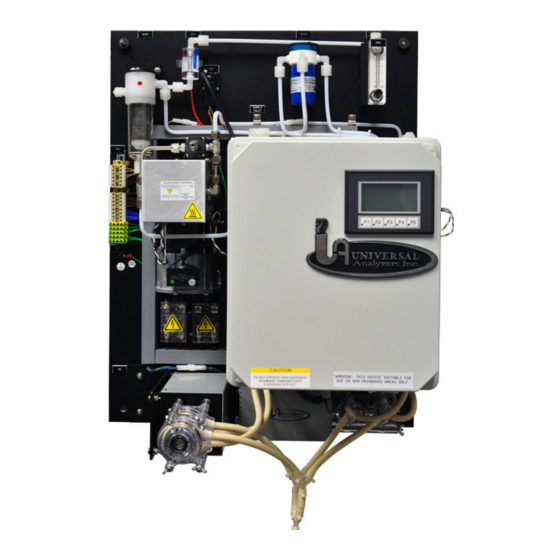
- Page 1 Model 1095E Acid Aerosol Freezer Chiller Instruction Manual 5200 Convair Drive • Carson City, NV 89706 +1 (775)883 2500 • sales.universal@ametek.com • www.universalanalyzers.com...
-
Page 2: Table Of Contents
TABLE OF CONTENTS RECEIVING AND STORAGE .......................... 3 DEFINITION OF SYMBOLS ........................... 4 SPECIFICATIONS ............................5 DESCRIPTION AND PRINCIPAL OF OPERATION ................... 6 TOUCH-SCREEN USER INTERFACE ........................8 4.1.1 MAIN DISPLAY/Operator interface ......................8 4.1.2 SYSTEM STATUS AND ALARMS ......................9 4.1.3 MAIN MENU ............................ -
Page 3: Receiving And Storage
1.0 RECEIVING AND STORAGE The Universal Analyzers Model 1095E Acid Aerosol Freezer Chiller is completely pre-assembled. No assembly is necessary when received on-site. Carefully inspect the product and any special accessories included with it immediately on arrival by removing them from the packing and checking for missing articles against the packing list. Check the items for any damage in transit and, if required, inform the shipping insurance company immediately of any damage found. -
Page 4: Definition Of Symbols
2.0 DEFINITION OF SYMBOLS CAUTION, RISK OF DANGER SYMBOL INDICATES INJURY MAY OCCUR IF MANUFACTURER’S INSTRUCTIONS ARE NOT ADHERED TO. PLEASE READ MANUAL CAREFULLY WHEN SYMBOL IS DISPLAYED CAUTION, HOT SURFACE SYMBOL INDICATES EXPOSED SURFACE TEMPERATURE CAN CAUSE BURNS OR PERSONAL INJURY. CARE SHOULD BE TAKEN WHEN CONTACT IS REQUIRED. -
Page 5: Specifications
3.0 SPECIFICATIONS OPERATING SPECIFICATIONS Sample Flow Rate 0 to 5 l/m total (at STP) Maximum Inlet Temperature Stainless Steel Heat Exchanger 700°F (351°C) Kynar/Glass Heat Exchanger 280°F (138°C) Maximum Inlet Gas Dew Point 178°F (81°C)* Maximum Inlet Water Concentration 50%* Minimum Ambient Temperature 34°F (1°C) Maximum Ambient Temperature... -
Page 6: Description And Principal Of Operation
4.0 DESCRIPTION AND PRINCIPAL OF OPERATION Application The Universal Analyzers Model 1095E Acid Aerosol "Freezer Chiller" is a system on a 21" x 27" plate designed to achieve an exit dew point of negative 13°F(-25°C). It is designed to remove moisture to a level of 650 PPM. - Page 7 A Moisture sensor is provided to sense the presence of condensate, should any exist in the tubing following the chiller. This CCSF (Condensate Carry-Over Sensor with Filter) includes a visible steel fiber filter. This allows the operator to inspect the condition of the filter. The integral moisture sensor with the sensing elements is located in the bottom of the filter bowl to provide an early warning if liquid carries over past the freezer chiller.
-
Page 8: Touch-Screen User Interface
TOUCH-SCREEN USER INTERFACE 4.1.1 MAIN DISPLAY/OPERATOR INTERFACE The Model 1095E "Freezer Chiller" is manually controlled through the Operator Interface located on the front of the unit, or remotely by the I/O inputs to the PLC. The 128x64 pixel operator interface (HMI) is used to display and manually operate the 1095E Chiller. -
Page 9: System Status And Alarms
4.1.2 SYSTEM STATUS AND ALARMS Status and alarm messages displayed on top of screen: MESSAGE COMMENTS/NOTES System Normal Condensate Carry-over Channel 1 Hi Temperature 39°F(4°C) Channel Channel 2 Hi Temperature -13°F(-25°C) Channel Channel 3 Hi Temperature -13°F(-25°C) Channel Column 2 Frozen Flow alarm before dwell timeout Column 3 Frozen Flow alarm before dwell timeout... -
Page 10: Main Menu
4.1.3 MAIN MENU This menu provides access to the System Control Menu (System) and the Sequence Times Menu (Sequence). The Main button returns the user to the main display screen. 1095E.MAN.REVD.072019 Page 10 of 23... -
Page 11: System Control Screen
4.1.4 SYSTEM CONTROL SCREEN The Acknowledge Alarms button is used to clear alarms displayed on the Main Display screen once the alarming condition has been corrected. The System Online Set Logic button is used to change the logic of the System Online/Offline digital input between Normally Open and Normally Closed The Advance Sequence button is used to advance the Freezer Channel cycle for troubleshooting. -
Page 12: Sequence Times Screen
4.1.5 SEQUENCE TIMES SCREEN The Dwell Time Minutes button allows the user to adjust Freezer Channel sequence time between 50 and 180 minutes. The Pre-Chill Time Minutes button allows the user to adjust the Next Up Channel pre-chill time between 20 and 40 minutes. System Defaults: The PLC will have following default values: •... -
Page 13: Installation
5.0 INSTALLATION The sample inlet is a 3/8” compression fitting supplied on the top of the first heat exchanger. The heat insulation on the heated tube bundle should be stripped no more than 3” to avoid plugging the exposed line. The sample outlets are 1/4"... -
Page 14: Start-Up
6.0 START-UP NOTE: IT IS IMPORTANT THAT THE HEATED PROBE AND HEATED SAMPLE LINE SHOULD BE AT OPERATING TEMPERATURE BEFORE STARTING THE CHILLER AND SAMPLE PUMP. Apply power to the sample cooler. Channel 1 temperature should start to drop immediately. It will be below the overtemperature set points, 50°F(10°C), after several minutes, once Channel 2 reaches 14°F(-10°C) the sample pump will turn on as the system leaves startup mode and enters run mode. -
Page 15: Shutdown
7.0 SHUTDOWN Before removing power from the unit, ensure the system has been purged of any potentially hazardous components. To purge the system, perform the following: 1. Perform a manual blowback operation. 2. If feasible, provide instrument air to the probe via a cal gas line. If not, disconnect the sample line. 3. -
Page 16: Maintenance
8.0 MAINTENANCE MAINTENANCE SCHEDULE DAILY 1. Check alarm status for normal operation 2. Check chiller temperature indication a. CH1 4°C ± 1°C b. Online Freezer - Cold c. Offline Freezer - Warm 3. Check sample flow rate through chiller to be normal < 5 l/min WEEKLY 1. -
Page 17: Installing Or Replacing Heat Exchangers
8.2.3 INSTALLING OR REPLACING HEAT EXCHANGERS REMOVING THE HEAT EXCHANGER 1. Remove the inlet and outlet tubes by loosening the compression fittings. Always use a backup wrench on the fitting body to ensure no damage to the heat exchanger occurs. 2. -
Page 18: Troubleshooting
9.0 TROUBLESHOOTING The following table should give an overview of possible errors and an instruction to check and to repair them (is not valid for the starting-up period of cooler). TROUBLESHOOTING SHOULD ONLY BE DONE BY AN TRAINED TECHNICIAN. Error Possible reason Check/Repair No display, no fans... - Page 19 Column malfunction (not Peltier devices not functioning Check cable & wiring connections Replace cooling) peltier devices Replace heat sink assembly High system vacuum System inlet vacuum >5" HG Blowback heated filter Replace heated filter for restriction Low sample flow Pump failure Replace sample pump Replace pump diaphragm RTD failure...
-
Page 20: Drawings And Spare Parts
10.0 DRAWINGS AND SPARE PARTS For the current revision of all Model 1095E drawings and spare parts, visit the Universal Analyzers website. https://www.universalanalyzers.com/ Navigate to: Products -> Sample Conditioning Systems -> Model 1095E Chiller System Links to all current drawings and spare parts for standard chiller systems are provided at the bottom of the page. -
Page 21: Standard Terms & Conditions Of Sale And Warranty
11.0 STANDARD TERMS & CONDITIONS OF SALE AND WARRANTY THE FOLLOWING TERMS/CONDITIONS, TOGETHER WITH ANY OTHER TERMS/CONDITIONS SPECIFICALLY AGREED TO IN WRITING BY SELLER, SHALL APPLY TO ALL ORDERS (“Order(s)”) FROM, AND SALES OF PRODUCTS (“Products”) OR SERVICES (“Services”) TO BUYER. ANY ACCEPTANCE OF ANY ORDER OF BUYER IS CONDITIONED UPON THESE TERMS/CONDITIONS. - Page 22 learns of or has reason to know of any violation of FCPA and/or VII. PATENTS/INDEMNITY or UKBA in connection with the sale or distribution of If Buyer receives a claim that Products, or part thereof Products/Services, Buyer shall immediately advise Seller. manufactured by Seller infringes a patent, Buyer shall notify C.
- Page 23 X. SOFTWARE/TECHNICAL/PROPRIETARY substantial harm to persons or property, unless Products have been specifically approved for such activity or application. INFORMATION Seller disclaims all liability for loss or damage resulting from A. Buyer shall not acquire any rights to any software which may such unauthorized use and Buyer shall defend, hold harmless be delivered with Products, except as granted in Seller’s and indemnify Seller against any such liability, whether arising...
Need help?
Do you have a question about the Universal Analyzers 1095E and is the answer not in the manual?
Questions and answers