Table of Contents
Advertisement
INSTRUCTIONS FOR INSTALLATION, USE
AND MAINTENANCE
PELLET BOILER
Mini
Read instructions carefully before installation, use and maintenance
The instruction manual is an integral part of the product.
Laminox S.r.l. reserves the right to change the characteristics and data reported in the following
document at any time and without warning in order to improve their products. This manual,
therefore, cannot be considered as a contract with third parties.
Updated manuals and drawings are available at website www.laminox.com.
Advertisement
Table of Contents

Subscribe to Our Youtube Channel
Related Manuals for LAMINOX Idro TERMOBOILER Mini Series

Summary of Contents for LAMINOX Idro TERMOBOILER Mini Series
- Page 1 The instruction manual is an integral part of the product. Laminox S.r.l. reserves the right to change the characteristics and data reported in the following document at any time and without warning in order to improve their products. This manual, therefore, cannot be considered as a contract with third parties.
- Page 2 CAUTION, READ CAREFULLY The TERMOBOILER models are a series of high-performance water boilers (over 92%), which exploits the combustion heat. The consequence of these performances is a low temperature of fumes exiting the boiler, around 60- 110°C. For this reason you must absolutely follow the requirements listed below : A.
- Page 3 Dear Customer, Thank you for choosing one of our products, which is a result of technological expertise and our continuous quest for superior products in terms of safety, reliability and performance. This manual contains all the information and helpful tips for using your product with maximum safety and efficiency. IMPORTANT INFORMATION This manual has been prepared by the manufacturer and is an integral and essential part of the product.
-
Page 4: Table Of Contents
GENERAL STANDARDS......................... 6 Fireplace or Chimney flue ........................ 6 Chimney pot ............................. 7 External air intake vent ........................8 Connection to the chimney flue ......................8 Preventing house fires........................8 SPECIFICATIONS AND TECHNICAL DATA.................... 9 Specifications ........................... 9 Technical data ..........................9 Rear connections dimensions ...................... - Page 5 WARNINGS AND MAINTENANCE ....................... 40 Opening the door ........................... 40 Ash drawer cleaning ........................40 Brazier cleaning ..........................40 Combustion chamber cleaning ....................... 40 Smoke chamber cleaning ....................... 41 Exhaust system cleaning ........................ 41 Cleaning metal and ceramic parts ....................41 Cleaning the glass ..........................
-
Page 6: General Standards
GENERAL STANDARDS In general, we refer to regulations concerning "heat generators fed with wood and other solid fuels", UNI 10683:2012. Fireplace or Chimney flue Each device must have a vertical duct, called chimney flue, for outside release of combustion fumes produced by natural draft. The chimney flue must meet the following requirements: •... -
Page 7: Chimney Pot
Chimney pot The top of the chimney flue must be equipped with a device, called chimney pot, which facilitates dispersion into the atmosphere of combustion products. The chimney pot must meet the following requirements: • Its internal section and shape must be equivalent to that of the chimney flue. •... -
Page 8: External Air Intake Vent
Horizontal width of Minimum height of the zone of reflux the outlet from the Height of the reflux Roof pitch ? [°] from the axis of the roof Hmin zone Z [m] ridge A[m] =Z+0.50m 1.85 1.00 0.50 1.50 1.30 0.80 1.30 2.00... -
Page 9: Specifications And Technical Data
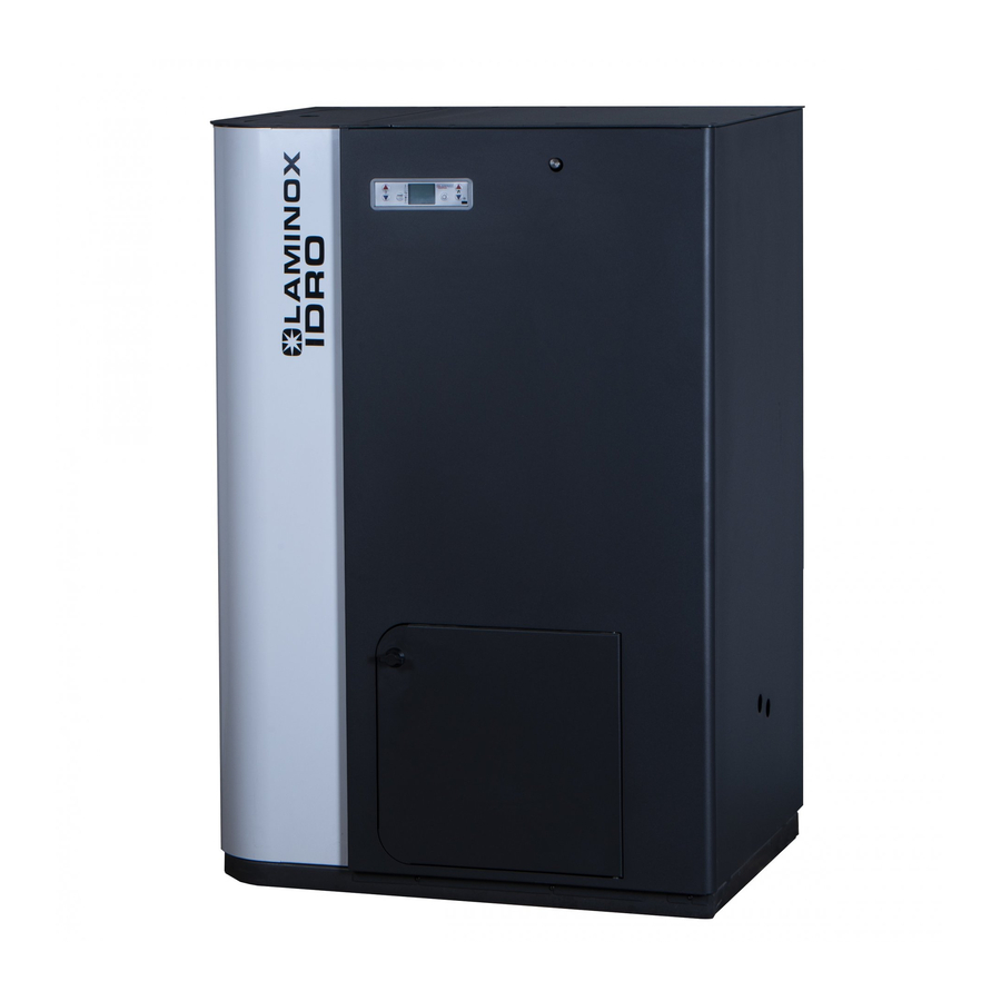
SPECIFICATIONS AND TECHNICAL DATA Specifications Stoves and pellet thermostoves are devices built to work with good quality wood pellets only (see par. 3 fuel), hydro models must be connected to the plumbing system. Technical data Termoboiler Mini Termoboiler Mini Termoboiler Mini Model Power to the brazier (kW) 13,5 kW... -
Page 10: Wiring Diagram
Wiring diagram... -
Page 11: Fuel
FUEL General notes The pellet boiler has been designed and certified to burn wood pellets only (*). Wood pellets are a fuel obtained from the pressing of sawdust timber, extracted from the processing and transformation residues of dried wood material. The compactness of the product over time is guaranteed by a natural origin substance contained in the wood: lignin. -
Page 12: General Notes
INSTALLATION General notes The heating system or appliance must be installed in order not to damage the building and other systems. The installer must strictly comply with standard UNI 10683:2012. 4.1.1 Installation in the presence of several appliances. The presence of several appliances powered with different fuels, as well as hoods with or without extractor, must be evaluated during preventive checks and during the start up test in order to detect any variation compared to the design conditions or any aspect that cannot be detected during the design phase. -
Page 13: Minimum Safety Distances
Minimum safety distances The following figures show the minimum safety distances which must always be guaranteed. 4.2.1 Corner installation (mm) 4.2.2 Wall installation (mm) Safety distances from flammable material P= 500 mm • Minimum distance in air from the flammable rear wall •... - Page 14 4.2.3 Distance from flammable ceilings and false ceilings (mm) Minimum mandatory distance from flammable material and from roof for maintenance H= 800 mm 4.2.4 Distance of fume exhaust system from flammable walls (mm)
-
Page 15: Flooring Protection
Flooring protection In the event of valuable flooring or flooring that is sensitive to heat, moisture or is flammable, a floor protection must be used (e.g. sheet steel, marble or tile slabs). Whichever type of protection selected, it must protrude at least 300 mm from the front and at least 150 mm from the sides of the boiler, withstand the weight of the boiler and have a thickness of at least 2 mm (fig. -
Page 16: Fume Exhaust Duct
Fume exhaust duct 4.5.1 General notes CAUTION: the pellet stove is not like other stoves. Fume draft is forced thanks to a fan that maintains the pressure in the combustion chamber and slight pressure around the exhaust duct. Therefore, you must verify that the latter is completely watertight and properly installed, both from the point of view of function and safety. - Page 17 4.5.3 Holes for exhaust tube passage on walls or roof: recommended insulation and diameter Once the location of the boiler has been decided (paragraph 4.1), you will have to drill the hole for passage of the fume exhaust tube. This varies depending on the type of installation (therefore on the diameter of the drain pipe, see 4.5.2) and type of wall or roof to pass through (tab.3).
- Page 18 Using an external fume duct An external fume duct can be used only if it meets the following requirements: • For the ducts, only insulated tubes (double wall) in stainless steel, secured to the building (fig.13) must be used. • An inspection area must be created at the base of the duct for performing periodic checks and maintenance.
-
Page 19: General Notes
ASSEMBLY General notes Here are some general recommendations to follow in order to prevent accidents or damage to the product: • Unpacking and installation must be performed by at least two people. • All handling operations must be carried out using appropriate means and in full compliance with safety regulations. -
Page 20: Hydraulic Connection
Hydraulic connection Connection of the boiler to the hydraulic system must be exclusively performed by qualified personnel, who is able to perfectly perform the installation, complying with the regulations in force in the Country of installation. If the installation of the boiler requires interaction with another pre-existing system equipped with another heating device (gas boiler, methane boiler, gasoline boiler, etc.), contacting qualified personnel able to respond to the conformity of the system, according to the requirements of the law in force regarding the subject, is more recommended. -
Page 21: Boiler Hydraulic Diagram
Boiler hydraulic diagram 1. Cleaning Gear motor 2. Cockpit sensor holder 3. Expansion tank 4. Vacuum thermostat 10/20 Pa 5. Vacuum thermostat 30/50 Pa 6. External sensor clamp 7. Manual reset 8. Serial port 9. Main switch 10. Power socket 11. -
Page 22: Use
The Termoboiler line boilers are designed to operate 24/7 365 days a year. The boiler has been designed to maintain the water it contains above 70°C. This way, water will always be available for the domestic environment heat request. This does not involve continuous pellet consumption, as the boilers are adjusted automatically according to the heat requests of the connected utility. -
Page 23: Console Description
• CAUTION: if during the ignition stage, ignition does not occur and you notice a lot of smoke in the combustion chamber, immediately turn off the stove and replace the pellets being used, as it may be too moist. Forcing ignition could make your stove a hazard. •... -
Page 24: First Ignition
6.1.1 Display functions Functions: BUTTON 4 Manual boiler start-up and shut-down • ON/OFF Exit from a sub-menu • • Exit from shut-down or alarm (and passage to off status) Functions: BUTTON 5 • Reduction in set power value POWER REDUCTION Switching from a sub-menu to the previous one •... -
Page 25: Ignition And Normal Operation
Ignition and normal operation Before igniting the boiler: • Check that the furnace door is locked. • Make sure that the pellet tank is full or contains enough pellet so that the boiler shall function for the desired amount of time. •... - Page 26 6.3.2 No start-up As stated if the combustion trigger is not detected a no ignition alarm is signalled, the display will show the message "AT 5 NO START" and an acoustic signal will be heard at regular intervals (if the buzzer function is active in Menu 6). To disable the alarm, hold and press the ON-OFF (4) (about 2 seconds).
- Page 27 6.3.4 Modulation based on boiler water temperature The boiler is equipped with boiler water temperature sensor that allows it to modulate its power according to the desired temperature. To set water temperature, press button "1". Press button "1" once and the bottom of the display will show the message "...
- Page 28 6.3.7 Brazier cleaning During normal operation in work mode, "BRAZIER CLEANING" is activated at set intervals. During this time, the display will show the message "BRAZIER CLEANING", boiler ventilation increases and the flame lowers in the brazier and in the MATIC models, with automatic cleaning, turbulator cleaning is enabled.
- Page 29 6.3.10 Remote control The boiler control panel has been designed to receive all functions even via supplied remote control. (CR2025 3V type battery) • Switching to boiler water temperature setting mode • In temperature setting mode, it increases the set value BUTTON 1 •...
-
Page 30: The Menu
7 THE MENU Pressing the button “3”grants access to the menu. It is divided into different items and levels that allow you to access board settings and programming. Menu items that allow you to access technical programming are protected by an access key. User menu The following table briefly describes the structure of the menu, focusing only on selections available to the user in this section. - Page 31 MENU 03 "CHRONO SET" Use this menu to enable and programme start-ups and shutdowns. There are eight different possibilities divided into three groups: • Daily programme: 2 start-ups and shutdowns valid each day. • Weekly programme: 4 start-ups and shutdowns, for which you can decide which days of the week they must be active.
- Page 32 7.3.2 Menu 3-2 “DAILY PROGRAMME” Allows you to enable, disable and set all daily programmable thermostat functions. After having putting the first parameter (M-3-2-01) “DAILY CHRONO” to "on", you can set two start- ups and two shutdowns. For each parameter, you can set the startup or shutdown time or the value "off", if you do not wish to activate the daily programming.
- Page 33 PROGRAMME 1 Menu level Selection Meaning Possible values M 3-3-02 START PROG 1 on time 00:00-23:50 -OFF M 3-3-03 STOP PROG 1 off time 00:00-23:50 -OFF M 3-3-04 MONDAY PROG 1 on/off M 3-3-05 TUESDAY PROG 1 on/off M 3-3-06 WEDNES-PROG 1 on/off M 3-3-07...
- Page 34 PROGRAMME 4 Menu level Selection Meaning Possible values M 3-3-29 START PROG 4 on time 00:00-23:50 - M 3-3-30 STOP PROG 4 off time 00:00-23:50 - M 3-3-31 MONDAY PROG 4 on/off M 3-3-32 TUESDAY PROG 4 on/off M 3-3-33 WEDNES- PROG 4 on/off M 3-3-34...
- Page 35 Menu 06 "BUZZER MODE" When "off," acoustic signal is disabled in the event of an alarm. When "on," sets off a buzzer when an alarm is activated. Menu 07 "INITIAL LOAD" When the display shows the message "OFF," allows you to preload pellets for a time equal to 90”. Press the “1”...
-
Page 36: Safety And Alarms
SAFETY AND ALARMS Safety devices CAUTION: During operation, some parts of the boiler (door, handle, ceramic parts) may reach very high temperatures, therefore be extremely careful, use caution, and always follow the instructions. If during operations any part of the boiler or the exhaust pipe leaks smoke, immediately turn off the boiler without removing the power supply and ventilate the room. -
Page 37: Alarms
8.1.3 Smoke temperature sensor The smoke sensor is directly connected to the electronic board and keeps operating temperature of exhaust fumes from the boiler under constant control, allowing safe use of the boiler. How it works If fume temperature exceeds the first pre-set temperature limit, the board passes into modulation mode. - Page 38 EACH ALARM CONDITION CAUSES IMMEDIATE BOILER SHUTDOWN To exit from an alarm condition, always press button "4" until the message "FINAL CLEANING" appears. You will also need to take additional steps, depending on the type of alarm generated If you do not exit from the alarm condition within a given time (a few hours), the alarm will be sent into boiler memory and the display will show the message "ALARM MEMORY".
- Page 39 AL 7 - Thermal safety This alarm is activated by intervention of the safety thermostat installed inside the boiler What to do • Put the boiler in stand-by by pressing the off button for a few seconds. • Wait and make sure that the combustion of pellets left in the brazier has been completed. •...
- Page 40 WARNINGS AND MAINTENANCE All maintenance operations (cleaning, potential replacements, etc.) must be carried out when the fire is out and the boiler is cold. In addition, do not use any abrasive substances. CAUTION: FAILURE TO CLEAN AFFECTS SAFETY Opening the door The door must remain closed during operation.
- Page 41 Smoke chamber cleaning To clean the smoke chamber, a manual movement is arranged on the turbolator unit inside the smoke chamber. Generally, clean the smoke chamber once a year (preferably at the beginning of the season) for best boiler operation. The frequency of this operation depends on the type of pellet used and the frequency of use.
- Page 42 • Thoroughly clean the smoke exhaust system: contact a professional chimney sweep for this purpose; • Clean all dust, spider webs, etc., the area behind the panels of the inner cladding, specifically the fans. • Disconnect the power cable; • Leave the fire door ajar to avoid humidity from getting into the fumes duct and risk oxidising the inner surfaces.
- Page 44 Laminox S.r.l. Divisione Idro Zona Industriale Callarella, 261/263 – 62028 SARNANO (MC) Italy Tel. +39 0733.657.622 – Fax +39 0733.657.494 www.laminox.com e-mail: export@laminox.com Termoboiler-Mini-rev 1.0/2019-EN...
Need help?
Do you have a question about the Idro TERMOBOILER Mini Series and is the answer not in the manual?
Questions and answers