Table of Contents
Advertisement
Quick Links
Advertisement
Table of Contents

Related Manuals for JTS IT-12M


Summary of Contents for JTS IT-12M
- Page 1 IT-12M / IT-12D Ver_2.1 59508-042-04...
- Page 2 IT-12M IT-12D Ver_2.1 INTERPRETATION User’s Manual SYSTEM...
- Page 3 For service, please contact the nearest JTS Service Centre. Do not take the equipment apart by unauthorized personnel. • All JTS products are guaranteed for 1 year except for the cases as follows caused by personal reasons: A : Damage or malfunction caused by personal factors such as dropping, striking and so on.
- Page 4 CAUTION RISK OF ELECTRIC SHOCK DO NOT OPEN TO REDUCE THE RISK OF ELECTRIC SHOCK,DO NOT EXPOSE THIS EQUIPMENT TO RAIN OR MOISTURE. CAUTION: To reduce the risk of electric shock, DO NOT open covers, no useable serviceable parts inside. Refer servicing to qualified service personnel only This label may appear on the bottom of the unit due to space limitations.
-
Page 5: Table Of Contents
Remark: JTS Company reserves the right to modify any issue without notice in advance. If any detailed information needed, please contact the local agent or JTS distributor in your region. JTS is the registered trademark of JTS Professional Co., Ltd. -
Page 6: System Introduction
The JTS IT-12 interpretation system consists of IT-12M and IT-12D. • The IT-12M works as main unit to provide power, input and output interface, and control. • The IT-12D is an interpreter console allowing two interpreters work together. Interpreters can choose either floor channel for original language for direct interpretation or relay interpretation available via the relay select key. -
Page 7: Product Introduction
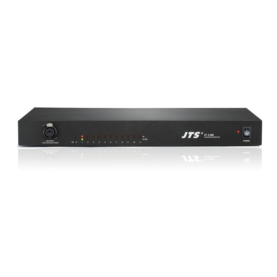
Power supply socket (3-wire grounding plus) with built in fuse, T2A/250V. DC power output: The IT-12M includ 12 outputs of DC power supply (+15V/500mA) to wireless transmitters, like JTS TG-10STX tabletop wireless transmitter. Interpreter console interface (D-sub 25pin socket):11 interpreter consoles can be connected in daisy chain (IT-12D). - Page 8 12CH audio output interface: #0 to 11 correspond to the Original (CH 0) and 11 sets of Interpreter Consoles. Signals are for distribution to audiences via JTS wireless systems. Notice: any channel not in use will be assigned with CH0 as input.
-
Page 9: Interpreter Console // It-12D
2-2 Interpreter Console // IT-12D MODE LOCK OPEN MIC INPUT INPUT OUTPUT MIC INPUT +48V PHANTOM POWER +48V PHANTOM POWER MICROPHONE OUTPUT CHANNEL ENTER VOLUME B VOLUME A MONITOR MONITOR ORIGINAL RELAY RELAY ORIGINAL MIC.A ON/OFF COUGH CUT SLOW COUGH CUT MIC.B ON/OFF ENTER key : At Lock Mode to set the active channel of interpreter console. - Page 10 +48V Phantom power. These balanced microphones will be mixed with MIC. A/B. Input interface (INPUT): to connect the first Interpreter Unit to the IT-12M and the second one to the Output interface of the first unit (25-pin socket).
- Page 11 Output interface (OUTPUT): for connection with the next Interpreter Unit (25-pin plug). Recorder interface (REC OUT): φ3.5mm stereo, for connection with a recorder to record the interpretation. (Available on both left and right side of the Interpreter Console). Microphone input (MIC IN): φ3.5mm dummy stereo, for connection with microphone(Available on both left and right side of the Interpreter Console).
-
Page 12: Accessories
(1) IT-12-C3: 3 meter cable with D-sub 25-pin M/F on each end. • Used to connect Interpreter Console (IT-12D) in daisy chain and to IT-12M. • Connecters: 1 Plug, 1 Socket. (2)HPM-535 : Multimedia Headset ( headphone with microphone) •... -
Page 13: System Installation & Connection
IT-12 Interpreter System has a compact dimension and is easy for installation. IT-12D interpreter consoles are connected in daisy chain and the first IT-12D is connected to the main unit IT-12M. A detailed description of IT-12 Interpreter System installation and connection will be given by diagrams and examples in this chapter. -
Page 14: System Connection // Connection Cables
IT-12D Interpreter Console to connect the interpreter unit to Main Unit IT-12M or to each other. On the rear panel of IT-12D there are two D-Sub connecters, the “INPUT” is a plug and the “OUTPUT” a socket. Connect the plug from the 25-pin cable to the Main unit IT-12M then the socket from the 25-pin cable to the plug “INPUT”... -
Page 15: Connection Of Audio Cables
(2)Connection for Balanced to Balanced transmission cable: Practical example: After the audios from wired and/or wireless microphones are mixed via the mixer, they go through to the IT-12M balanced input “LINE IN” (φ6.3mm jack) via balanced output. The cable can be as long as 200M... - Page 16 (3)Connection for Unbalanced to Balanced XLR transmission cable: Practical example: the recording output of IT-12M “REC. OUT” (unbalanced output) to PA system or media recording input XLR interface (balanced input). The cable can be as long as 200M Audio signal cable(double-core shielded cable)
-
Page 17: System Mounting Instructions
A pair of rack mount brackets are equipped with the IT-12M , unscrew the screws on both sides firstly , then fasten the brackets with these screws and put the IT-12M in the rack, finally install the unit onto the rack with 4 screws INTERPRETATION SYSTEM... -
Page 18: System Setup & Operation
Interpreter Console must be assigned with one unique output channel before being used. The procedure is as: a. Make sure the connection is correct, and then turn on the IT-12M. b. Turn the “SET” setting switch from “OFF” on the rear panel of the Interpreter Console to “ON”, the indicators of “ENTER”... - Page 19 When the speaker speaks too fast for the interpreter to follow, the interpreter can press “SLOW” key to remind the speaker to slow down. A pulse signal will come out as remind from the IT-12M to the speaker desk. g. Each Interpreter Console accommodates A/B two interpreters to work, the opera- tion A/B interpreter is the same.
-
Page 20: Technical Data
5-1 System environmental Conditions ○ ○ Transport Temp.: -40 C~+70 ○ ○ Operational Temp.: 0 C~+45 Max. Relative humidity: <95% 5-2 Main Unit IT-12M Technical Data Item..........Specification Power supply......110-240Vac System consumption... DC power output....+15V/0.3A*12 D-SUB power output..DC+15V/2A Line In sensitivity.... - Page 21 Interpretation Unit (IT-12D) Technical Data Item..........Specification Unit power........DC+15V Unit power consumption. 100mA±10mA MIC sensitivity......-45dB±2dB XLR MIC sensitivity.... -45dB±2dB Earphone output level..120mV±10mV at 33Ω load, volume MAX. REC OUT output level..140mV±10mV Protocol......... RS-485 In/Out interface...... D-Sub 25P plug and socket Dimension (LxWxH)..
Need help?
Do you have a question about the IT-12M and is the answer not in the manual?
Questions and answers