Table of Contents
Advertisement
Quick Links
Advertisement
Table of Contents

Related Manuals for JTS IT-12


Summary of Contents for JTS IT-12
- Page 1 IT-12M4 V2.0 / IT-12D Ver_2.1 59508-065-02...
- Page 2 IT-12M4 IT-12D Ver_2.1 INTERPRETATION User’s Manual SYSTEM...
- Page 3 For service, please contact the nearest JTS Service Centre. Do not take the equipment apart by unauthorized personnel. • All JTS products are guaranteed for 1 year except for the cases as follows caused by personal reasons: A : Damage or malfunction caused by personal factors such as dropping, striking and so on.
- Page 4 CAUTION RISK OF ELECTRIC SHOCK DO NOT OPEN TO REDUCE THE RISK OF ELECTRIC SHOCK,DO NOT EXPOSE THIS EQUIPMENT TO RAIN OR MOISTURE. CAUTION: To reduce the risk of electric shock, DO NOT open covers, no useable serviceable parts inside. Refer servicing to qualified service personnel only This label may appear on the bottom of the unit due to space limitations.
-
Page 5: Table Of Contents
Remark: JTS Company reserves the right to modify any issue without notice in advance. If any detailed information needed, please contact the local agent or JTS distributor in your region. JTS is the registered trademark of JTS Professional Co., Ltd. -
Page 6: System Introduction
• The product is a stand along system. It is compatible with any conference system. So no matter a new installation or an existing project needing expansion with interpretation IT-12 can easily meet the requirement. • Together with JTS wireless system and any infrared system more audiences can participate in a... -
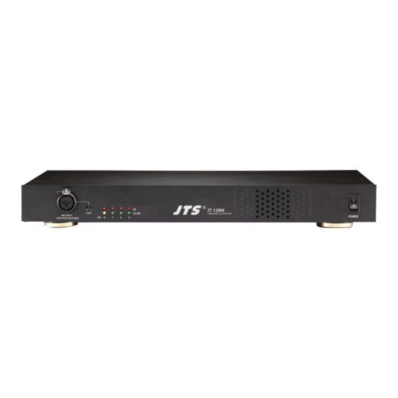
Page 7: Product Introduction
DC power input: To connected the 12V /1A power adapter that included in package of IT-12M4 from JTS . Don’t used other spec power adapter insead. Interpreter console interface (D-sub 25pin socket):3 interpreter consoles can be connected in daisy chain (IT-12D). - Page 8 4CH audio output interface: #0 to 3 correspond to the Original (CH 0) and 3 sets of Interpreter Consoles. Signals are for distribution to audiences via JTS wireless systems. Notice: any channel not in use will be assigned with CH0 as input.
-
Page 9: Interpreter Console // It-12D
2-2 Interpreter Console // IT-12D MODE LOCK OPEN MIC INPUT INPUT OUTPUT MIC INPUT +48V PHANTOM POWER +48V PHANTOM POWER MICROPHONE OUTPUT CHANNEL ENTER VOLUME A VOLUME B MONITOR MONITOR ORIGINAL RELAY RELAY ORIGINAL MIC.A ON/OFF COUGH CUT SLOW COUGH CUT MIC.B ON/OFF ENTER key : At Lock Mode to set the active channel of interpreter console. - Page 10 the channel is activated the Channel Output Key is in green. The indicator flashes in red which means this channel is in use by others. Note: MIC. ON/OFF at OFF state, the activate channel will be released when this channel number on other interpreter console is selected. Relay interpretation monitor (MONITOR): After pressing RELAY key, an interpreter can turn the monitor rotary knob to select an interpreted language he/she can understand to interpret.
- Page 11 input sockets with +48V Phantom power. These balanced microphones will be mixed with MIC. A/B. Input interface (INPUT): to connect the first Interpreter Unit to the IT-12M4 and the second one to the Output interface of the first unit (25-pin socket). Output interface (OUTPUT): for connection with the next Interpreter Unit (25-pin plug).
-
Page 12: Accessories
2-3 Accessories Accessories are standard parts for a complete system installation, general description are as follow: (1) IT-12-C3: 3 meter cable with D-sub 25-pin M/F on each end. • Used to connect Interpreter Console (IT-12D) in daisy chain and to IT-12M. -
Page 13: System Installation & Connection
3. System Installation & Connection 3-1 General Description IT-12 Interpreter System has a compact dimension and is easy for installation. IT-12D interpreter consoles are connected in daisy chain and the first IT-12D is connected to the main unit IT-12M4. A detailed description of IT-12 Interpreter System installation and connection will be given by diagrams and examples in this chapter. -
Page 14: System Connection // Connection Cables
4 languages (including floor channel) interpretation. Extension cables can be used between Interpreter Consoles and Main Unit IT-12M4 (IT-12-C3/C6/C12/ C18). It is strongly recommended to use JTS tailor-made cables to ensure the best performance. IT-12M4 MICROPHONE OUTPUT CHANNEL... -
Page 15: Connection Of Audio Cables
3-3 Connection of Audio Cables Cable connection plays an important role in the long distance audio transmission. Improper connection will result in interference. For example: (1)Connection for Unbalanced to Balanced transmission cable: Practical example: after the audios from signal source of mono RCA output, they go through to the IT-12M4 balanced input “LINE IN”... - Page 16 (3)Connection for Unbalanced to Balanced XLR transmission cable: Practical example: the recording output of IT-12M4 “REC. OUT” (unbalanced output) to PA system or media recording input XLR interface (balanced input). The cable can be as long as 200M Audio signal cable(double-core shielded cable) A jack: Signal source(unbalanced output) B jack: Reception(balanced intput) RCA jack...
-
Page 17: System Mounting Instructions
3-4 System Mounting Instructions IT-12M4 Main unit Installation (1)Dimension (LxWxH):421 x 213 x 44mm (2)Colour: Silvery black (3)Weight: 2 Kg (4)“L” shape rack mount bracket for 1U 19-inch standard cabinet. (5)Mounting Instructions A pair of rack mount brackets are equipped with the IT-12M4 , unscrew the screws on both sides firstly , then fasten the brackets with these screws and put the IT-12M4... -
Page 18: System Setup & Operation
4-1 General Description This chapter provides a comprehensive and detailed description on how to setup and op- erate IT-12 Interpreter System Main Unit (IT-12M4) and Interpreter Console (IT-12D). (1)OPEN Mode: Interpreter Console Output Channel Select (IT-12D) Select the Console with one of the Channel Output key ‘1, 2, 3”; for example: If you want this unit to be NO. - Page 19 (4)The Operation of IT-12D Interpreter Console: The Interpreter Console is designed with digital technologies and used in conjunction with HPM-12 interpreter headset. Each Console allows two interpreters to work on it. The operation procedures are as follows: a. At LOCK mode, when the output channel is selected an interpreter only need push the MIC ON/OFF key to activate the microphone or deactivate it.
-
Page 20: Technical Data
5. Technical Data 5-1 System environmental Conditions ○ ○ Transport Temp.: -40 C~+70 ○ ○ Operational Temp.: 0 C~+45 Max. Relative humidity: <95% 5-2 Main Unit IT-12M4 Technical Data Audio Input........... Ø6.3mm balanced, unbalanced Level:0.775V Combo XLR Level: 2mV Audio Output..........Floor Output: RCA*2 Symmetrical, RCA*6 Output Freq-Response...... - Page 21 Interpretation Unit (IT-12D) Technical Data Item..........Specification Unit power........DC+12V Unit power consumption. 100mA±10mA MIC sensitivity......-45dB±2dB XLR MIC sensitivity.... -45dB±2dB Earphone output level..120mV±10mV at 33Ω load, volume MAX. REC OUT output level..140mV±10mV Protocol......... RS-485 In/Out interface...... D-Sub 25P plug and socket Dimension (LxWxH)..
Need help?
Do you have a question about the IT-12 and is the answer not in the manual?
Questions and answers