Table of Contents
Advertisement
Advertisement
Table of Contents

Related Manuals for TRONXY P802M


Summary of Contents for TRONXY P802M
- Page 2 Classification Of Screws M2.5*10mm black M3*20mm screws M3 nuts 60pcs screws 2pcs 58pcs M3*30mm screws M3*10mm screws M8 nuts 12pcs 7pcs 17pcs M8 Cushion ring M3*14mm screws Plastic Pillars 4pcs 12pcs 4pcs...
- Page 3 Classification Of Screws M4*15mm screws M3*30mm screws 4pcs 12pcs M3*20mm screws Wing nuts*4 Compression springs*4 4pcs...
- Page 4 Step 1 Assemble Y-axis Motor Fit the GT2-16 pulley on the motor, Locking with M3*2mm jackscrew. As the picture, Put Y-axis motor on <Y-axis motor support> , locking with Four M3*10mm screws. GT2-16 pulley Y-axis motor M3*2mm jackscrew Y-axis motor support M3*10mm...
- Page 5 Step 2 Assemble Y-axis Limit switch Put the Y-axis limit switch and the holder together ,locking with two M3*20mm screws & nuts. As picture M3*20mm screws Y-axis limit switch Y-axis limit switch holder (Acrylic) M3 nuts...
- Page 6 Step 3 Assemble Base Frame Holder_Back Sliding rod As the picture, put two of the Sliding rod Restriction*2 Restriction in front of the base frame holder (back). locking with two M3*20mm screws & nuts. M3*20mm M3 nuts screws Put the limit switch and holder assembly on the base frame holder, locking with one M3*20mm screw &...
- Page 7 Step 4 Assemble Base Frame Holder_Front As the picture, put two of the Sliding rod Restriction in front of the base frame holder _front. locking with two M3*20mm Round head screws & nuts. Base Frame Put Y-axis belt pulley wheel assembly behind the Holder_Front base frame holder, Locking with two M3*20mm Y-axis belt pulley...
- Page 8 Step 5 Assemble Extruder Bearing Install 3pcs Bearings to the U-Metal Plate, Locking with 12pcs M4*8mm screws. U-Metal plate Put Motor& Hotend module and U-Metal plate together , locking with 2pcs M3*10mm screws . Motor & Hotend Put Fan and Fan Holder to the U-Metal plate, and Metal Block locking with 2pcs M3*22mm screws ...
- Page 9 Step 6 Assemble Z-axis motor coupling Put two Z-axis motor support(side) in two sides of the motor, Cover the Z-axis motor Z-axis motor support(top) on the top, locking with support(top) M3*20mm screws & nuts. The cable of Z-axis motor is back of the Z-axis motor support.
- Page 10 Step 7 Assemble Z-axis As the picture, Put the two Z-axis motors assembly on the left and right side of the Bottom plate, locking with three M3*20mm screws & nuts. M3*20mm screws Z-axis motor assembly The hole is on the left Bottom plate M3 nuts The hole is on the right...
- Page 11 Step 8 Assemble Side plate As the picture, Put the two Side plate on the left and right side of the Bottom plate , locking with four M3*20mm screws & nuts. Side plate M3*20mm screws...
- Page 12 Step 9 Assemble Top plate & Junction Plate Sliding rod As the picture, Put the Top plate on Side restriction Plate, locking with four M3*20mm screws & nuts. Junction Plate Put the two Junction Plate on the top of the Side plate ,locking with four M3*20 screws &...
- Page 13 Step 10 Install LCD display LCD display assembly Put the LCD display on the top of the Top plate ,locking with three M3 nuts M3*25mm screws &nuts M3*25mm Framework screws (top half)
- Page 14 Step 11 Install Z-axis Limit switch Put the Z-axis limit switch on the left side of Bottom plate, Locking with two M3*20mm screws and nuts. Z-axis limit switch M3*20mm screw & nut...
- Page 15 Step 12 Install Power supply Put Power supply on the right of the side plate , locking with three M3*14mm screws and nuts. Side plate Power supply M3*14mm screw...
- Page 16 Step 13 Install PCBA Control Board Install Control Board as picture , locking with Four M3*30mm screws + 4pcs Plastic pillars + 4pcs M3 nuts Plastic Pillars*4 M3 Nuts*8 M3*30mm Screws *4 Side plate Control Board...
- Page 17 Step 14 Install Base frame holder_Back Put the Base frame holder_back back of Side plate, locking with four M3*20mm screw M3*16mm screws*4 Base frame holder_back...
- Page 18 Step 15 Install Base Frame Holder_Front Through the Frame Holder_Front & Back by two M8*400mm screw arbors, locking with twelve M8 Nuts & cushion ring. M8 nuts M8 cushion ring M8*400mm Base frame screw arbors holder_front...
- Page 19 Step 16 Assemble Bed frame Place three bearings under the bed frame, locking with twelve M4*15 screws. Bearing*3 M4*15mm screws *12...
- Page 20 Step 17 Assemble Bed frame Place three bearings under the bed frame, locking with twelve M4*15 screws. Through the bed frame on the base by two of M8*380mm Sliding rod. Fix both end by Sliding rod restriction Tighten one end of the timing belt to the bed frame using a zip-ties.
- Page 21 Step 18 Assemble Heatbed Place the MK3 heatbed on the bed frame use 4pcs springs between them, and then through 4pcs M3-30mm screws, top 4pcs wing nuts under the bed frame. MK3 Heatbed Springs*4 M3*30mm screws *4 Wing nut*4...
- Page 22 Step 19 Instal X-axis Motor & Pulley mount Put X-axis motor on X-axis motor mount. X-axis Motor Locking with three M3*10mm screws. Through the X-axis motor mount & pulley Sliding rod mount by M8*380mm sliding rod & restriction M8*345mm screw arbor.
- Page 23 Step 20 Assemble X-axis Through the X-axis motor mount & Extruder Pulley mount and Extruder assembly assembly using two M8*443mm sliding rods, as the picture. Put X-axis limit switch on the X-axis motor mount, locking with two M8*443mm sliding rod M2.5*10mm screws (small black screw) X-axis motor...
- Page 24 Step 21 Instal X-axis Timing Belt Tighten one end of the Timing Belt to the X-axis timing belt Belt clip with Nylon cable ties. The other end through the X-axis pulley & motor , then tighten another end of the belt to the another Belt clip with Nylon cable ties .
- Page 25 Step 22 Control Board Wiring Diagram The method of connecting wire is as picture !NOTE!: The wires connected to POWER SUPPLY and HETBED must be AWG14 or thicker one. Wire the X Y Z axis Limit switches “COM” and “NO” these 2 ends , as pictures...
- Page 26 Step 23 AC Power Connector Wiring Diagram Connect Power cable as the picture (Right) Note: There are different voltages in different country. Please select the appropriate voltage by switch before power on. As the picture below.
- Page 27 Step 24 Assemble Filament Feeder Separately put two Plastic Pipe holder on two Filament support frame, locking with Plastic Pipe four M3*20mm head screws & nuts. Connect the two Filament support frames with two Fixed links , locking with four M3*20mm screws &...
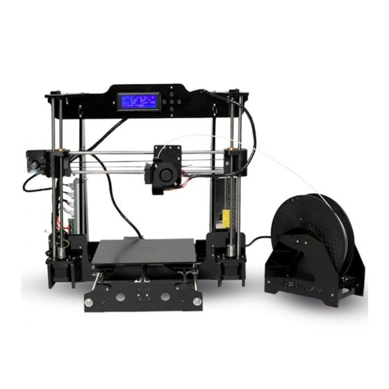
- Page 28 Installation Finished...
Need help?
Do you have a question about the P802M and is the answer not in the manual?
Questions and answers